2001 RPi CM4 Ultra EN
Keywords
Raspberry, CM4 Core board, 2.5G Ethernet, NVME SSD, WiFi6, 5G, RPiOS, eMMC, OpenWrt, Video Capture
I. Introduction
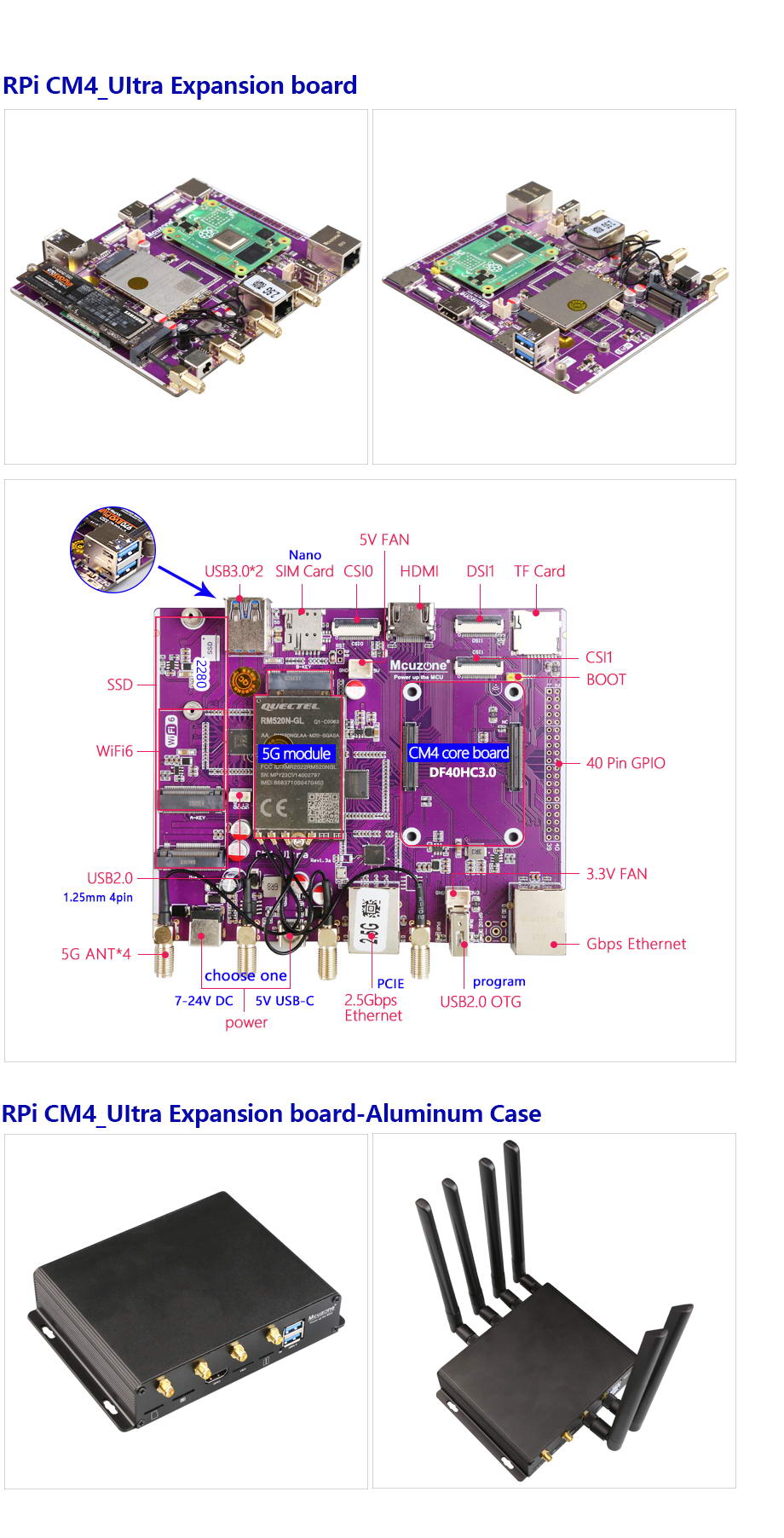
The CM4_Ultra expansion board is an expansion board designed based on the Raspberry Pi CM4 core board. It expands the single PCIe interface of the CM4 into four PCIe interfaces using a switch chip. The CM4_Ultra expansion board features one PCIe M.2 M-KEY interface for connecting an NVMe SSD, one PCIe 2.5G Ethernet port, one PCIe M.2 A-KEY interface for connecting WiFi 6, and one PCIe expansion for USB 3.0. Additionally, one of the USB 3.0 ports is connected to an M.2 B-KEY interface for external 5G expansion. The expansion board supports all versions of the Raspberry Pi CM4 core board. The expansion board is ideally suited for a variety of applications requiring high-speed data acquisition, processing, and communication, such as WiFi 6 testing terminals, remote image and video capture systems, live streaming, vehicle infotainment systems, TBOX-like vehicle data access devices, integrated media players, facial recognition, soft routers, gateways, remote image transmission, edge computing, and more.
II. Hardware Spec
| Power Supply | 1*DC input, wide voltage range of 7-24V, DC5.5-2.1 connector.
1*USB-C 5V3A port, supports PD charger; two power sources cannot be used simultaneously. |
| Nerwork | 1*native Gigabit Ethernet port.
1*PCIe 2.5G Ethernet port (RTL8125 chip). 1*PCIe M.2 A-KEY interface for expanding WiFi 6. 1*USB 3.0 M.2 B-KEY interface for connecting 5G, with a Nano SIM card slot and onboard 4 SMA antenna connectors. |
| Storage | 1*PCIe M.2 M-KEY slot, supporting 2280-sized NVMe SSD, does not support SATA/GNFF drives.
1*TF card slot, used for booting the system with the lite version of the Raspberry Pi CM4 core board; if using the CM4 core board with eMMC, this TF card slot will be unavailable. |
| USB Ports | 2*USB 3.0-A host ports.
1*USB 2.0 port, 1.25mm-4P. 1*USB OTG port (USB-A), also the programming port for the eMMC core board. |
| Display | 1*standard HDMI port supporting 4K resolution.
1*DSI1 (22PIN, 0.5mm, flip-down connection). |
| Camera | 2*CSI1(22PIN, 0.5mm, flip-down connection). |
| Others | 2*fan power supplies, 2.54mm-2P, 5V and 3.3V.
1*boot jumper, 2.54mm-2P, for flashing the eMMC core board. 40PIN GPIO, 2.54mm 20*2, fully compatible with the GPIO pins of Raspberry Pi 4B. |
| Size | 111*135mm, immersion gold process, lead-free production, PCB board certified by UL and ROHS, flame retardant rating 94V-0.
Optional aluminum alloy case with 4 fixing holes for easy equipment installation, case size: 114*154*31mm. |
The pin definitions for the 40-pin connector, from left to right:
| 5V | 5V | GND | G14 | G15 | G18 | GND | G23 | G24 | GND | G25 | G08 | G07 | IDSC | GND | G12 | GND | G16 | G20 | G21 |
| 3V3 | G02 | G03 | G04 | GND | G17 | G27 | G22 | 3V3 | G10 | G09 | G11 | GND | IDSD | G05 | G06 | G13 | G19 | G26 | GND |
III. System flashing
Raspberry Pi OS: 2024-07-04-raspios-bookworm-arm64.img.xz
You can download it in:
https://www.raspberrypi.com/software/operating-systems/#raspberry-pi-os-64-bit
3.1 Boot from TF card
If the Raspberry Pi CM4 core board does not have eMMC, the system will boot from the TF card.
Click here to the burning method instructions
3.2 Boot from eMMC
If the Raspberry Pi CM4 core board has onboard eMMC, it can only boot from the eMMC, and the onboard TF card will be ineffective.
First, you need to install the driver package for the Raspberry Pi CM4 core board on your PC. You can download it from the official Raspberry Pi website or from our company's website:
http://www.mcuzone.com/down/Software.asp?ID=10000623
Then, use a jumper cap to short the BOOT pin and the GND pin, and connect the USB 2.0 OTG interface on the expansion board to the computer using a USB Type-A cable (as shown in the figure below):
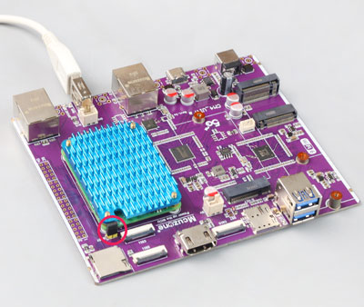
After connecting to the computer, open the Device Manager, and a new USB device will appear. In the image below, the USB device is named "BCM2711 Boot".

Under the All Programs section of the PC's Start menu, there is an rpiboot under Raspberry Pi.

Open this software, and the computer will format and partition the eMMC or TF card.

Wait a moment, and a partition will appear in the file explorer (in this example, the partition is named bootfs, but the actual name may var

Next, we can use the balenaEtcher to flash the image to this partition.
Please open the balenaEtcher software, click on the first option "Flash from file," and select the file you want to flash to the eMMC. For the second option, choose the bootfs partition mentioned above, then click "Flash now" to start the flashing process.


After the burning process is completed, we need to remove the previously inserted short-circuit cap (otherwise the core board will not start properly), then power it on again to boot the system.
IV. Work with Raspberry Pi OS
4.1 Ethernet test
4.1.1 Ethernet connection
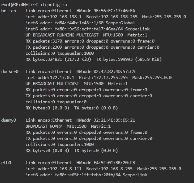
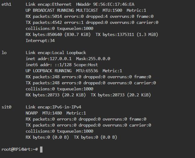
Connect the gigabit Ethernet port to the upstream router, and execute ifconfig -a on the terminal, which displays the following:
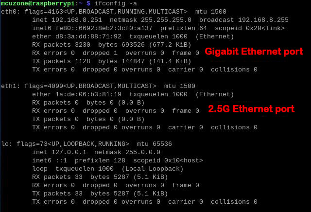
eth0 is a native Gigabit network card and has obtained an IP address.
eth1 is an extended 2.5G network card, but since no network cable is plugged in, it has not acquired an IP address.
4.1.2 2.5G Ethernet speed test
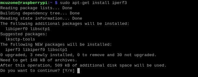
We plug the Ethernet cable into the 2.5G port, and the system will automatically obtain an IP address. Then, we open the terminal and install the speed-testing tool iperf3.
sudo apt-get install iperf3
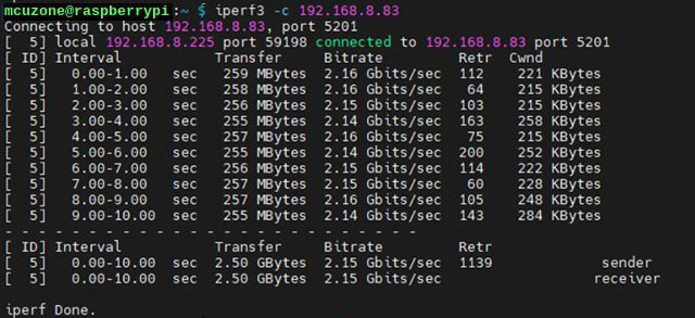
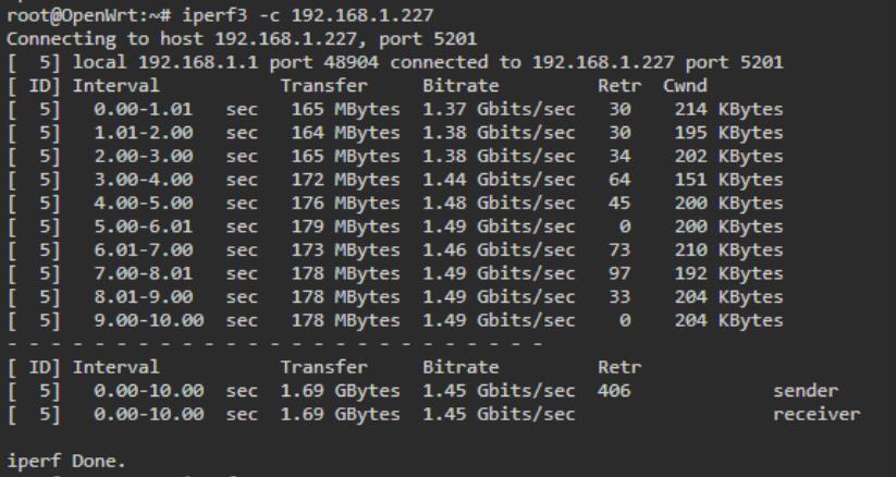
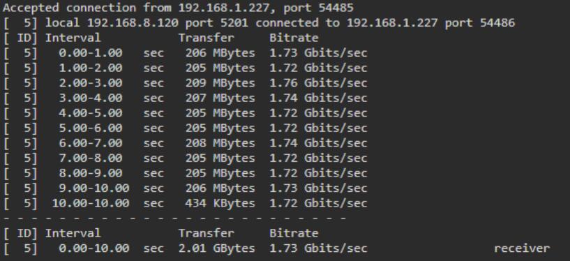
2.5G Ethernet speed test results:
2.15Gbps (client mode).
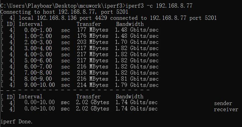
1.75Gbps (server mode).
Note: The speed test results of 2.5G networks are affected by network conditions and testing methods. The actual speed may vary, and this test is for reference only.
4.1.3 Gigabit Ethernet speed test
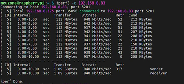
We plug the network cable into the native Gigabit Ethernet port, and the system will automatically obtain an IP address. Then, we open the terminal and test using iperf3.
Native Gigabit Ethernet speed test results:
940Mb/s (client mode).
Note: The speed test results of 2.5G networks are affected by network conditions and testing methods. The actual speed may vary, and this test is for reference only.
4.2 SSD test
4.2.1 Basic operations of SSD drives
NVMe SSDs are for data storage only and cannot be used as a system boot drive.
In Raspberry Pi OS, when you open the File Manager, you can see the partitions of the SSD. The screenshot is shown below:
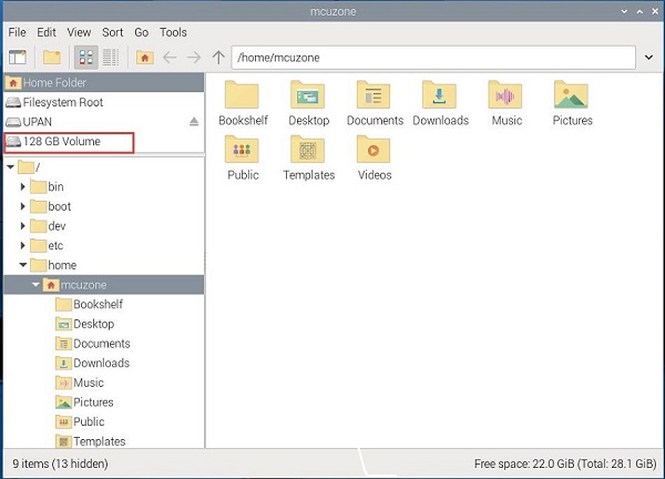
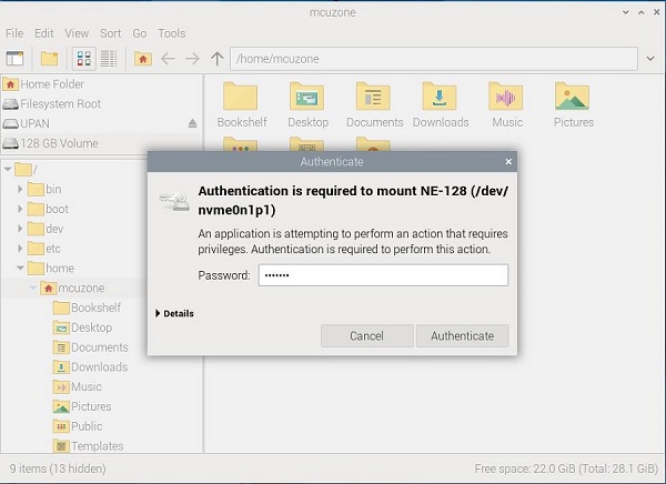
To operate the SSD, click the partition icon, enter the system password, and then click "Authenticate". After successful authorization, you can perform operations on the SSD.
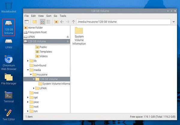
Now, when you return to the desktop, you will see the shortcut icon for the SSD partition.
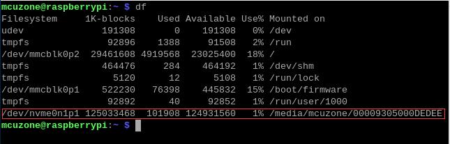
You can also enter df in the terminal to see the SSD partition and its mounting information. We can use this SSD as a storage device.
If you need to perform operations such as partitioning and permanently mounting an SSD, please refer to this page.
4.2.2 SSD speed test
4.2.2.1 SSD interface speed test
We use the hdparm to test the SSD drive interface speed.
Install the hdparm software:
sudo apt install hdparm
Run the command multiple times to test the SSD speed repeatedly.
sudo hdparm -t /dev/nvme0n1
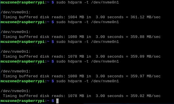
The test result shows that the SSD's interface speed is around 360MB/s.
4.2.2.2 Install the SAMBA file sharing service
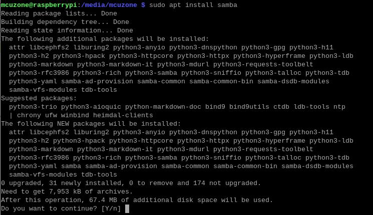
SAMBA is a software for sharing files between Windows and Linux. We can use it to transfer files between Windows and Raspberry Pi via Ethernet, which allows us to test network speed.
Install SAMBA:
sudo apt install samba
Create a new folder under the SSD path for sharing files and modify the folder permissions.
cd /media/mcuzone/writable
sudo mkdir ssdfiles
sudo chmod +777 ssdfiles

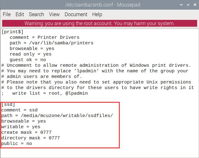
Modify the SAMBA configuration file to add a shared node.
sudo mousepad /etc/samba/smb.conf
Add the shared node at the end of the file:
[ssd]
# Shared folder instruction
comment = ssd
# Shared Folder Directory
path = /media/mcuzone/writable/ssdfiles/
# Mount path of the shared directory that needs to be mapped
browseable = yes
# Resource name publicly visible (content hidden, set to 'Yes')"
writable = yes
# Writable
create mask = 0777
# New files are created with 777 permissions.
directory mask = 0777
# New files are created with 777 permissions.
public = no
# Guest access without a password (set to "No" here)
Note: If you need to add more mapped folders, please continue adding new shared nodes in the same format, ensuring that the shared folder description and shared folder directory are not duplicated. The local path should be filled in according to the mounted path.
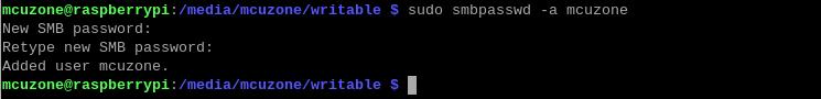
Create a user named mcuzone1; you will be prompted to set a password afterward.
sudo smbpasswd -a mcuzone
Restart SAMBA:
sudo systemctl restart smbd

Then, map a network drive in Windows, using Windows 11 as an example here.
Open "This PC", then click "Map network drive".
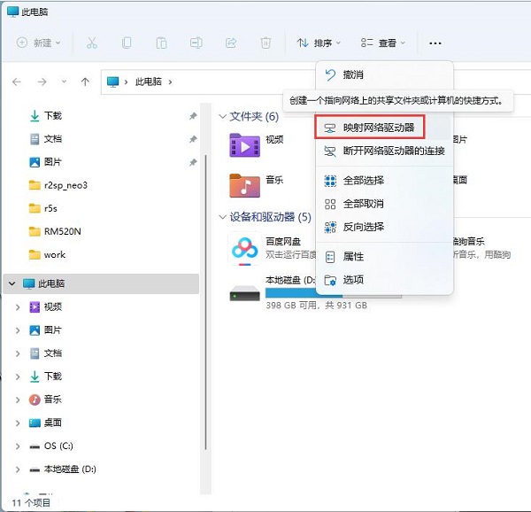
Fill in the relevant node information according to the diagram below (the IP is the Raspberry Pi OS IP):
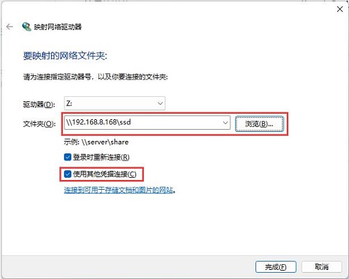
Enter the username and password you just set:
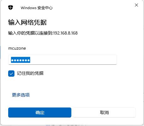
Then, the shared folder that was set up was opened.
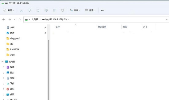
Note: Before setting up a shared folder, you must grant permission to the SSD partition in the Raspberry Pi OS. Otherwise, you will encounter a "network name not found" error when configuring the shared folder.
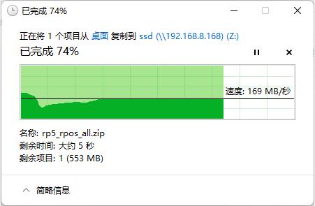
4.2.2.3 SSD R/W testing over a Gigabit Ethernet port
Connect the network cable to the Gigabit Ethernet port, then conduct R/W speed tests on the SSD drive via the SAMBA file sharing service.
Write:
Read:
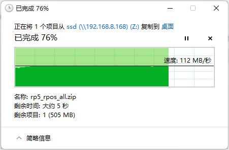
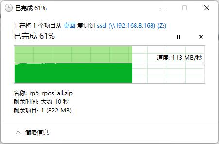
4.2.2.4 SSD R/W testing over a 2.5G Ethernet port
Connect the network cable to the 2.5G Ethernet port, then conduct R/W speed tests on the SSD drive via the SAMBA file sharing service.
Write:
Read:
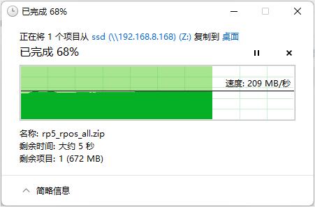
Note: The speed of the SSD drive test is influenced by various factors such as network conditions, hard drive quality, file storage status, and OS environment. The above test results are for reference only and should not be considered as the final parameters of the actual product. In practical tests, the read speed can reach up to 270MB/s.
4.3 DSI test
The official Gen 1 Raspberry Pi LCD screen needs separate power and requires an adapter board and DSI-compatible expansion board.
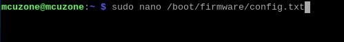
After connecting, power on the board. Wait for the OS to run, then open the terminal and execute the following commands
sudo nano /boot/firmware/config.txt
Add the following statements at the end of the file:
dtoverlay=vc4-kms-dsi-7inch
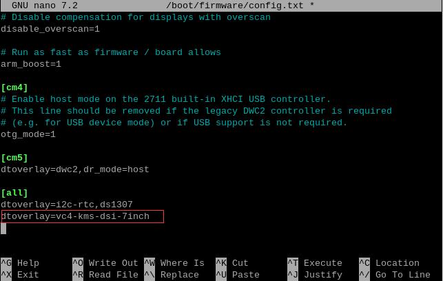
After saving, restart the OS to use the official Raspberry Pi 7-inch touchscreen.
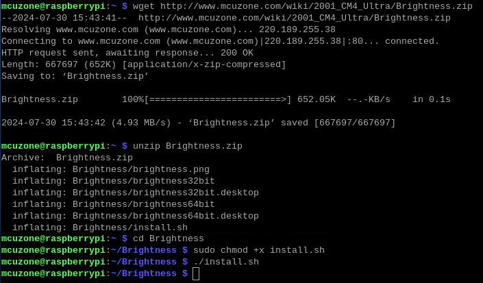
Upon restart, execute the following commands in the terminal in order.
wget http://www.mcuzone.com/wiki/2001_CM4_Ultra/Brightness.zip
unzip Brightness.zip
cd Brightness
sudo chmod +x install.sh
./install.sh
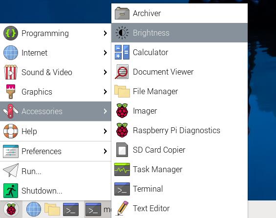
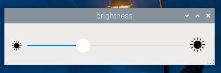
Then you can open the Brightness window from the Accessories menu to adjust the backlight of the 7-inch screen.
4.4 CSI test
We tested using the OV5467 camera, connecting it to either the CSI0 or CSI1 interface. After connecting, power on the board, open the terminal, and execute the following commands:
sudo nano /boot/firmware/config.txt
Add the following statements at the end of the file:
dtoverlay=ov5647,cam0
dtoverlay=ov5647,cam1
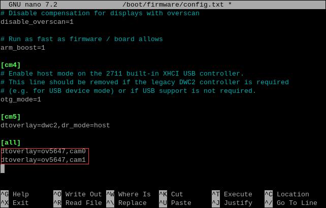
In actual use, add the configuration according to your model, save the changes, and then restart the system to enable the OV5647 camera.
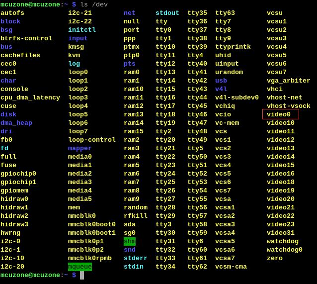
After rebooting, execute the following command in the terminal:
ls /dev
You can then see the video0 and video1 devices (inserting one camera displays video0, inserting two cameras displays video0 and video1, regardless of whether they are connected to CSI0 or CSI1).
To preview the camera feed, execute libcamera-hello --camera 0 or libcamera-hello --camera 1 in the terminal (a single connected camera is camera 0, while two cameras are assigned as camera 0 and camera 1).

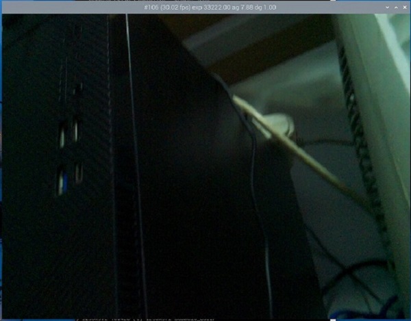
If a photo is required, please execute:
libcamera-jpeg -o test.jpg

Save the photo in the /home/mcuzone directory (i.e., the user's home directory). The photo effect is as follows:
4.5 USB test
After the system boots up, we plug the wireless keyboard and mouse into the OTG interface, insert two USB 3.0 SD card readers into the USB 3.0 ports, and enter lsusb to check the USB devices.
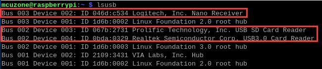
Bus 002 Device 003: USB3.0-A, USB3.0 SD card reader.
Bus 002 Device 004: USB3.0-A, USB3.0 SD card reader.
Bus 003 Device 002: USB2.0-A (OTG) interface, wireless keyboard and mouse.
Verify that all identifications are normal; then run lsusb -t to check the USB ports' operating mode.
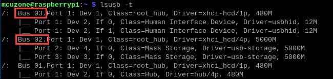
Bus 02: 5000M USB interface (USB 3.0).
Bus 03: 480M USB interface (USB 2.0).
All operating modes are functioning normally.
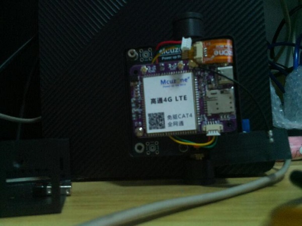
4.6 5G module test
Testing based on the Quectel 5G module RM500U-CN. The 5G module is now configured, working plug-and-play with the official Raspberry Pi OS.
(If the user has their own 5G module, they need to configure it themselves or integrate the driver, otherwise plug-and-play will not be possible, and this section cannot be referenced.)
4.6.1 5G test
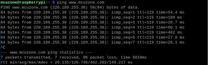
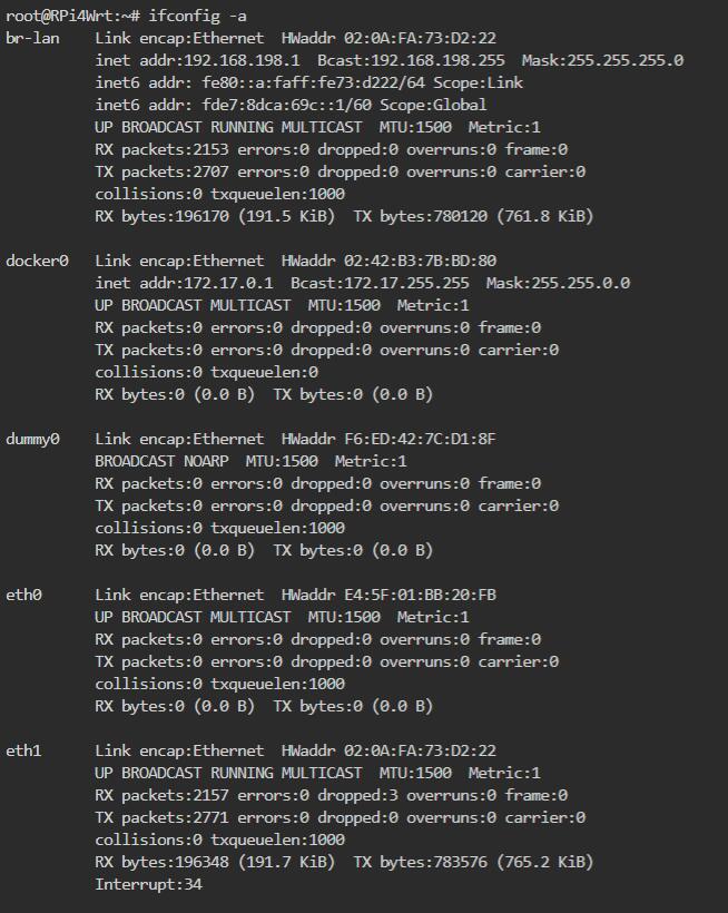
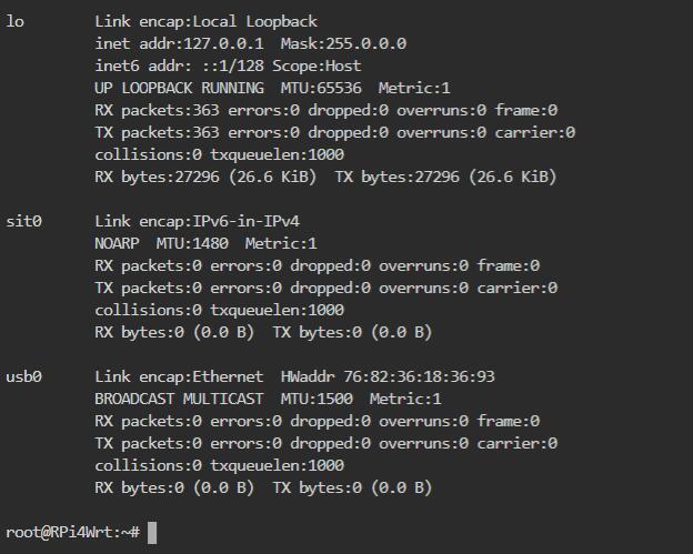
In the terminal, execute the command ifconfig -a, and you can see the following network information:
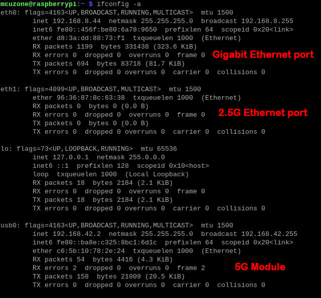
From the figure above, it can be seen that both the Gigabit Ethernet card and the 5G module have obtained IP addresses, and we have successfully pinged the website.
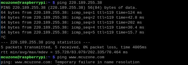
But if you disconnect the network cable, then pinging the IP succeeds, while pinging the domain name fails, as shown in the figure below:
Therefore, it is necessary to check whether the OS's nameserver (i.e., the DNS server) is correct. Use the following command to open the resolv.conf file:
sudo nano /etc/resolv.conf

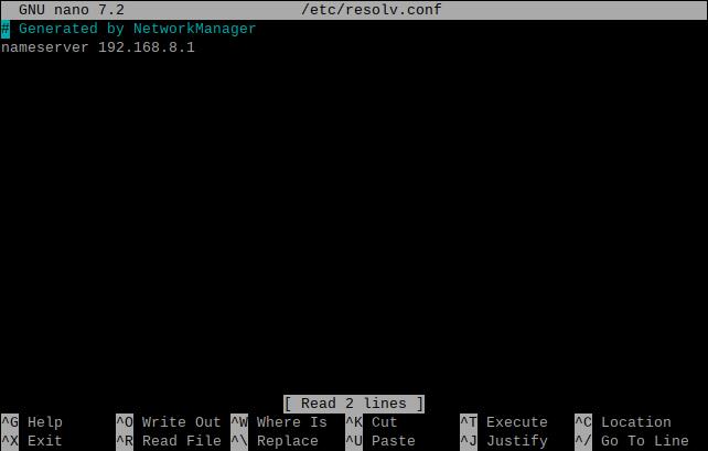
Please check if the current nameserver is correct. If not, change it to the SIM card's nameserver (usually its gateway address) or some common nameserver addresses (such as 114.114.114.114, etc.).
However, after a system reboot, the DNS entries in the resolv.conf file will revert to the default addresses. Therefore, if you need to enable 5G internet access automatically on startup, you will also need to modify the permissions of the resolv.conf file. Since /etc/resolv.conf is actually a soft link, you must recreate the resolv.conf file to change its permissions. The method is as follows:
sudo mv /etc/resolv.conf /etc/resolv.conf.link
sudo nano /etc/resolv.conf
This recreates the resolv.conf file. Add the following content to the new file:
nameserver 114.114.114.114
Save and exit, then execute:
sudo chattr +i /etc/resolv.conf
After performing the above steps, the resolv.conf file will remain unchanged even after a system restart.
4.6.2 Modification of Network Priority
When both Ethernet and 5G are connected, the default preference is to use the 5G network for internet access.
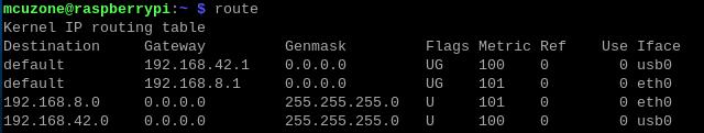
Execute the route command to view the routing table. Since usb0 is listed first, the internet connection is currently through the 5G module.
If you want to prioritize the wired network for internet access, you can execute the following command:
sudo ip route del default && sudo route add -net default netmask 0.0.0.0 gw 192.168.8.1
Explanation of these two commands (separated by '&&'):
sudo ip route del default: Remove the default route from the routing table.
sudo route add -net default netmask 0.0.0.0 gw 192.168.8.1: Add the gateway of the wired network as a new default route (ensure to use the actual gateway address).
After the execution is completed, execute the route command to view the routing table. The current default route is the gateway of the wired network (eth0 ranks first):
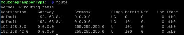
This way, the network will default to using the wired connection. If you need to switch back to defaulting to the 5G network, please execute the following command:
sudo ip route del default && sudo route add -net default netmask 0.0.0.0 gw 192.168.42.1
Or, you can reboot the system.
Note that 192.168.42.1 is the default gateway for the 5G module; please refer to the actual configuration.
Note: After a reboot, the routing table resets. To ensure the network continues to use the wired or wireless connection as the default route post-restart, you'll need to execute sudo ip route del default && sudo route add -net default netmask 0.0.0.0 gw 192.168.8.1 again.
4.6.3 5G network speed test
We unplugged the network cable, leaving only the 5G network connection, and then entered the speed test website to conduct a speed test.
The results are as follows:
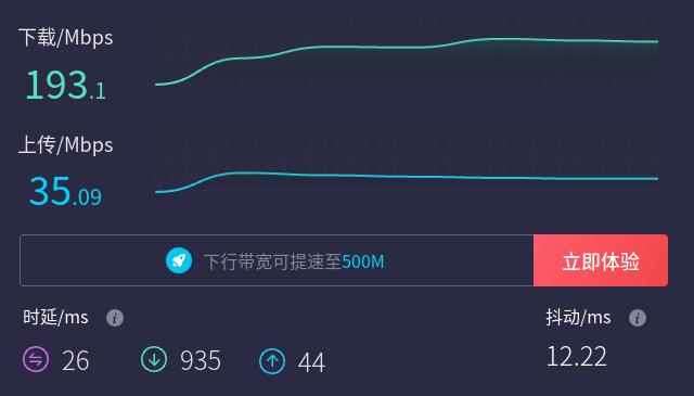
Note: The 5G module network speed test is affected by 5G signal and testing methods. The actual speed may vary, and this test is for reference only.
4.6.4 AT command operation
Connect the 5G module to the expansion board. After the system starts, we enter lsusb, and the display is as follows:
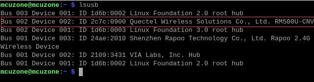
Note down the ID value of the 5G module: 2c7c 0900。
Download minicom:
sudo apt-get install minicom

Use the following command to enable the ttyUSB serial port of the 5G module, where the value after echo is the ID value recorded earlier:
sudo modprobe option
sudo sh -c 'echo 2c7c 0900 > /sys/bus/usb-serial/drivers/option1/new_id'
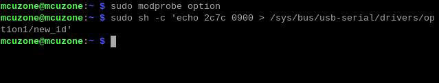
After executing the above two commands, execute the following:
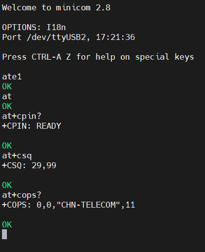
sudo minicom -D /dev/ttyUSB2

After entering minicom, we input AT commands for testing:
If you need to check the echo, type the command: ate1, then press Enter. Continue typing other commands and press Enter to see the results.
Common AT commands:
1) Check if the SIM card is detected:
at+cpin?
If ready is returned, the card is recognized; if error is returned, check the hardware.
2) Check antenna signal quality:
at+CESQ
3) Check network registration status:
at+cops?
Normally, it should return the network supporter's code: 7, where 7 represents 4G, and where 11 represents 5G.
Note: The above command at+CESQ should not include a question mark, while the other two commands require a question mark.
4) View the SIM card's IMEI code:
at+cgsn
5) Disable radio frequency:
at+cfun=0
Enable radio frequency:
at+cfun=1
The two commands mentioned above can be used in pairs to allow the module to re-register with the network without restarting the 5G module.
6) Switch SIM card
Use SIM1 (silkscreen marking):
AT+QUIMSLOT=1
Use SIM2 (silkscreen marking):
AT+QUIMSLOT=2
When switching slots, if the original slot has a card, Windows will prompt for ejection. Power off the module, move the card to the other slot, and restart. If the target slot already contains a card, it will work directly.
7) The USB port and Ethernet port cannot be used simultaneously, and can be switched via AT commands:
Use USB port:
AT+QMAPWAC=0
Use Ethernet port:
AT+QMAPWAC=1
4.7 WiFi6 test
The CM4_Ultra expansion board supports WiFi 6 (AX200) and WiFi 6E (AX210) modules, both of which require driver installation to function. The steps for installing the drivers are as follows:
4.7.1 Install driver
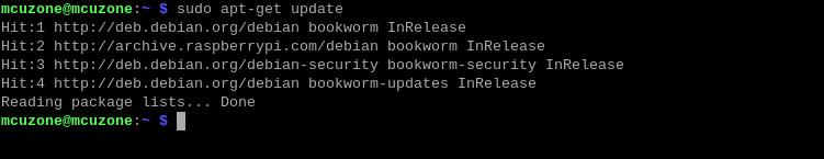
First, update the system and header files. Open the terminal and execute sudo apt-get update to update the system:
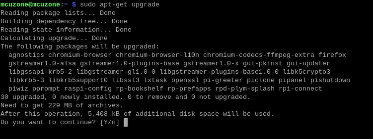
Then input: sudo apt-get upgrade
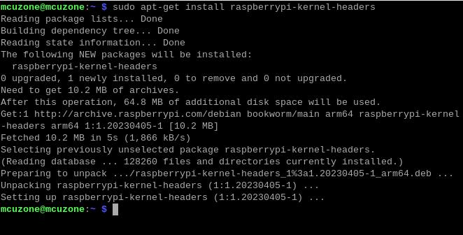
Finally, execute sudo apt-get install raspberrypi-kernel-headers to install the header files.
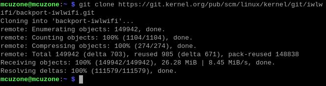
Download the WiFi driver source code to your local machine:
git clone https://git.kernel.org/pub/scm/linux/kernel/git/iwlwifi/backport-iwlwifi.git
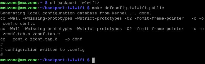
After downloading, cd backport-iwlwifi to enter the source directory, then run make defconfig-iwlwifi-public to output the .config file.
Execute:
sed -i 's/CPTCFG_IWLMVM_VENDOR_CMDS=y/# CPTCFG_IWLMVM_VENDOR_CMDS is not set/' .config

Execute make -j4, where -j4 indicates compiling with four cores. If the system freezes or gets stuck, you can try compiling with -j1 or -j2.

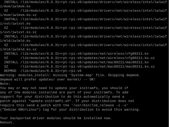
After compiling, execute sudo make install to install the driver:

After the installation is complete, you will be prompted to restart. Please do not restart yet.
4.7.2 Install firmware
Different modules have different firmware, and the one we use here is the AX210.
Execute the following commands in the terminal one by one:
cd ..
cd Downloads
wget http://www.mcuzone.com/wiki/2001_CM4_Ultra/iwlwifi-ty-a0-gf-a0-59.zip
unzip iwlwifi-ty-a0-gf-a0-59.zip
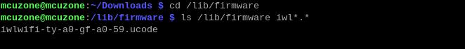
sudo cp iwlwifi-ty-a0-gf-a0-59.ucode /lib/firmware
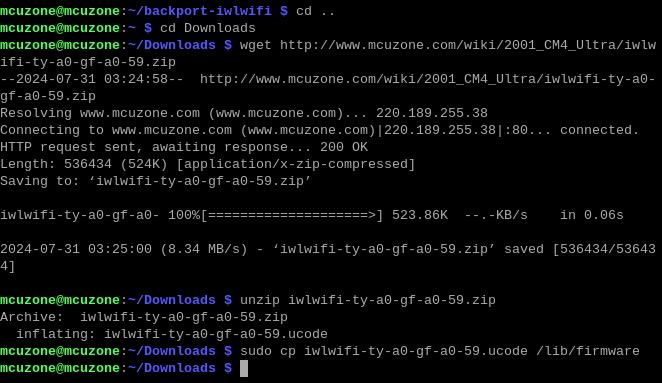
Then enter `cd /lib/firmware`, followed by `ls /lib/firmware iwl*.*`. If the file `iwlwifi-ty-a0-gf-a0-59.ucode` is listed, it indicates that the firmware has been successfully installed.
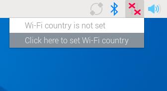
4.7.3 Test WiFi6 module
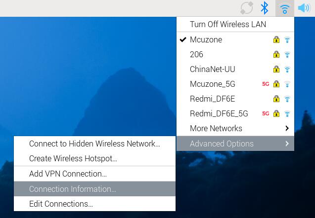
After the firmware installation is complete, restart the system, click the network icon in the upper right corner of the desktop, and then click "Click here to set Wi-Fi country".
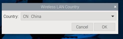
We select CN:
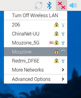
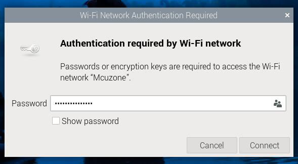
Restart the system again, then manually connect to the WiFi in the upper right corner of the desktop and enter the password:
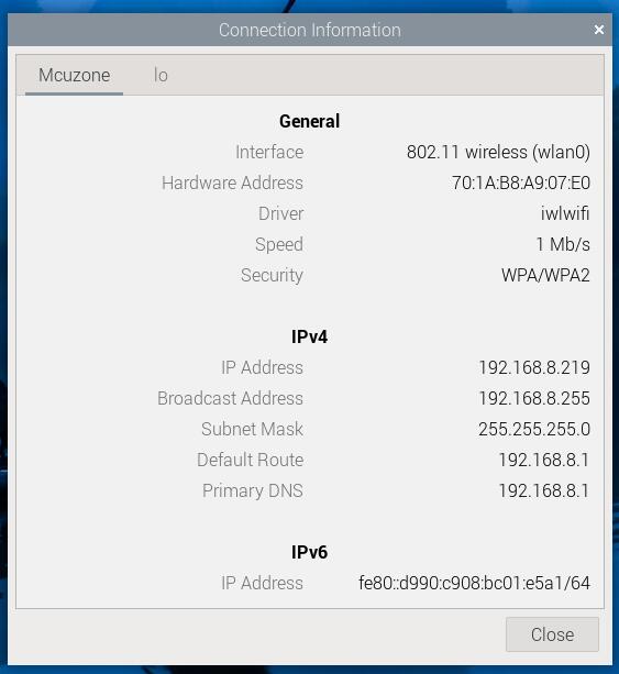
Once WiFi is connected successfully, view the network parameters:
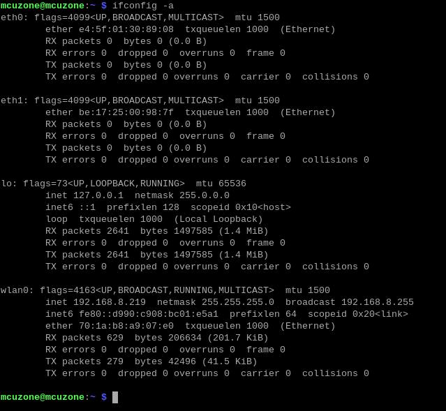
Executing ifconfig -a in the terminal can also display network parameters (wlan0).
V. Work with OpenWrt
The OpenWrt version we used for testing is: openwrt-bcm27xx-bcm2711-rpi-4-squashfs-sysupgrade-linux-6.1.98-20240723.img.gz. This system already includes the WiFi6 driver and the driver for our company's compatible 5G module.
The CM4_Ultra expansion board can be configured in OpenWrt as a one-in-one-out switch mode, with the native Gigabit port on the expansion board serving as the WAN port (connected to the Internet) and the 2.5G Ethernet port configured as the LAN port for connecting to a PC.
5.1 Login system
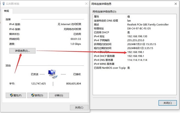
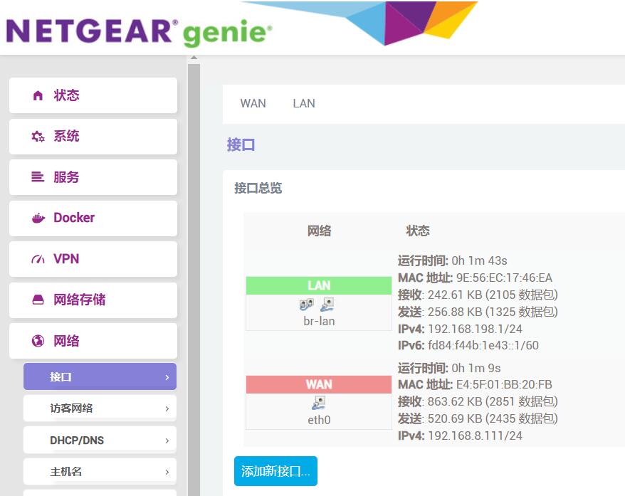
Connect the native Gigabit port on the expansion board to the PC's Ethernet port. After powering on the system, go to Network & Internet settings in Windows, open the connected network under Ethernet, and check the default gateway IP address. This address is the backend configuration page address of the OpenWrt. As shown in the figure, the tested address in this article is 192.168.198.1:
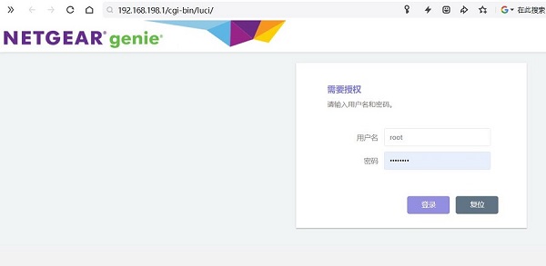
Then open a web browser, enter 192.168.198.1 to access the OpenWrt system. The default username is root, and the default password is password.
5.2 Network interface configuration
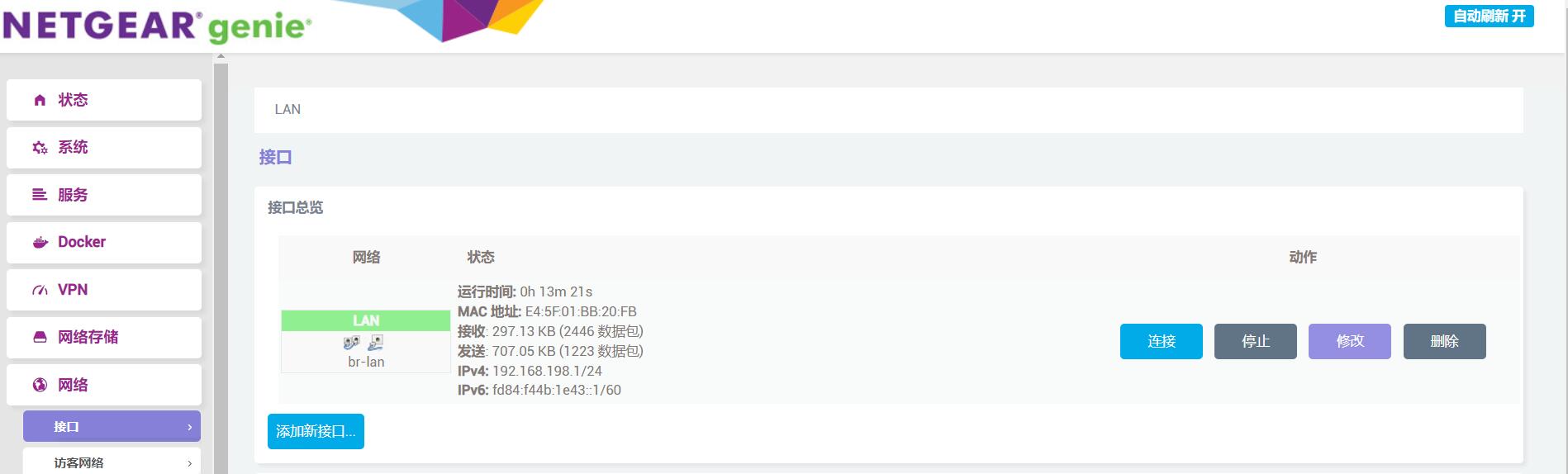
Open "Network - Interfaces", then click "Add new interface":
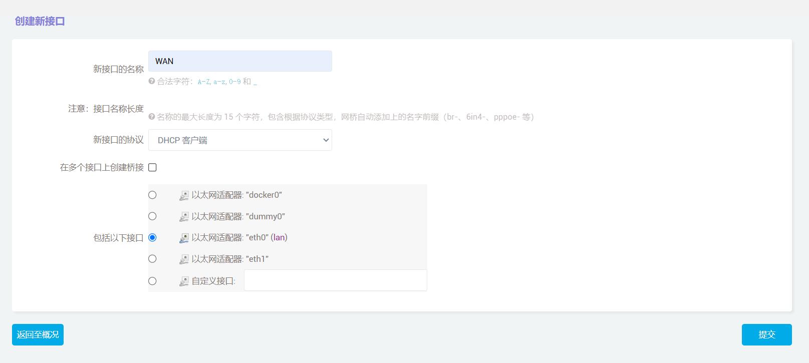
Set the interface name to "WAN", select "DHCP client" for the interface protocol, choose "eth0" for the interface, and then click the "Submit” button.
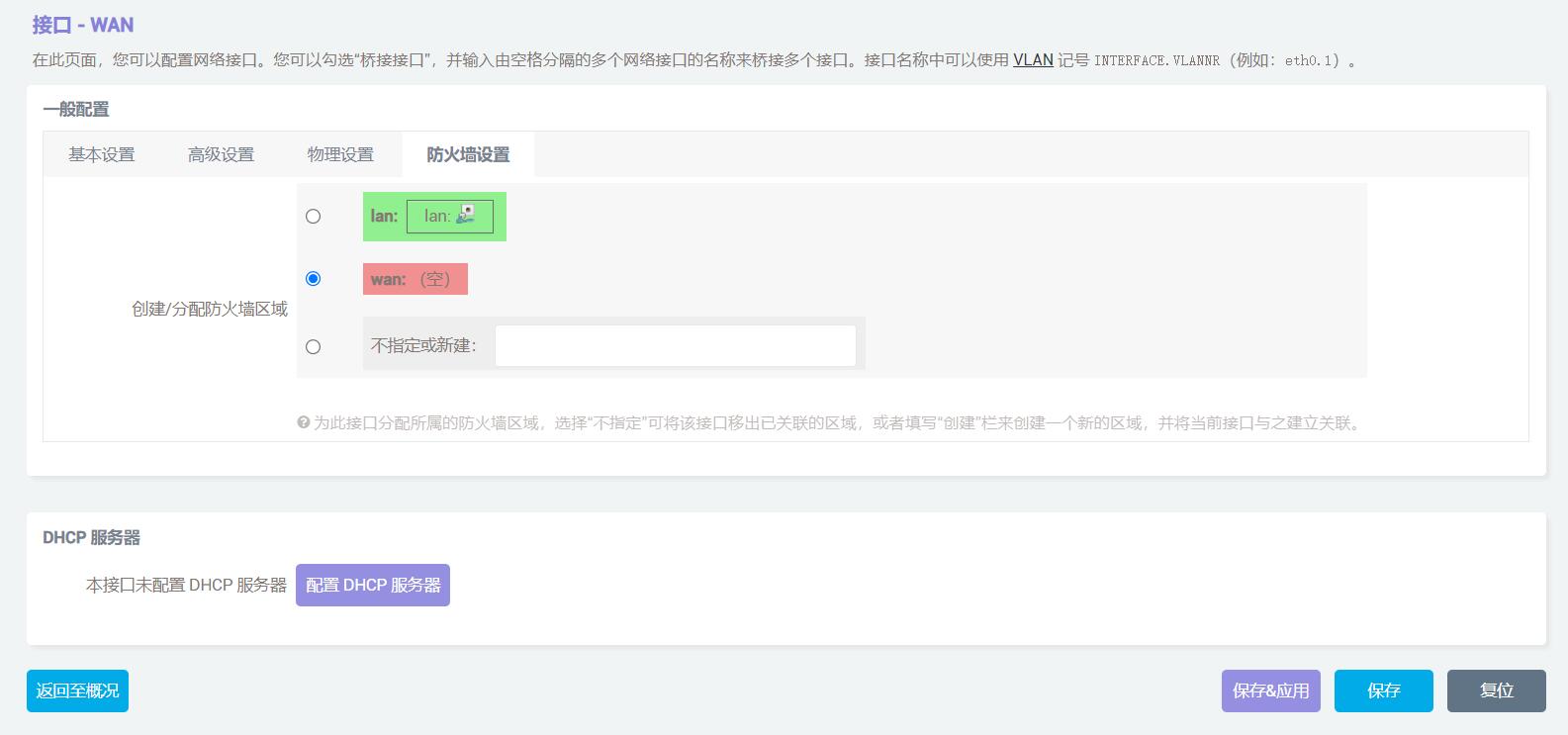
In the firewall settings, choose the WAN port and click "Save". Do not click "Save & Apply".
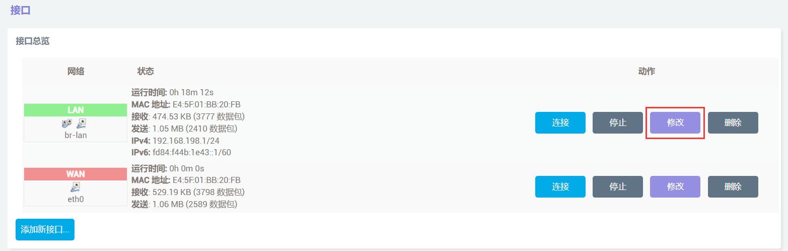
Then click the "Return to Overview" button, and at the interface, click the "Modify" button for the LAN port.
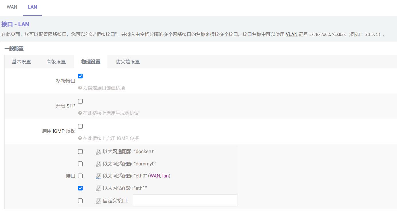
In the physical settings, change the interface to eth1:
Then click the "Save & Apply" button, and the network configuration will be completed.
5.3 2.5G Ethernet port test
After the network configuration is completed, the native Gigabit Ethernet port becomes the WAN port, and the 2.5G port becomes the LAN port. Switch the Ethernet cable connected to the computer to the 2.5G port, then connect the native Gigabit port to the upstream router.
Access the OpenWrt page, click on "System - TTYD Terminal", after logging in (the default username is root, and the default password is password), enter ifconfig -a to check the IP address.
Here, eth0 is a 2.5G network card, and eth1 is a Gigabit network card.
You can also check the network port information under "Network - Interfaces".
Next, we will use the iperf3 speed testing software (pre-installed in the system) on the TTYD terminal to conduct speed tests between the device and the PC:
When the expansion board acts as the client:
When the expansion board acts as the server:
Note: Network speed test results are influenced by network conditions and testing methods. Actual speeds may vary, and this test is for reference only.
5.4 SSD test
After logging into the admin panel, go to "System > Mount Points" to see the SSD automatically mounted.

Click on "Network Storage - Network Sharing". Be aware that there may be two "Network Sharing" options; choose the one marked Samba, not Ksmbd!
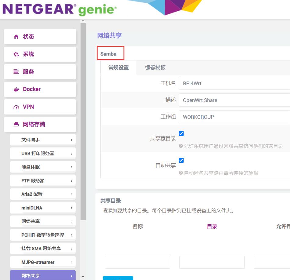
Add a shared directory, with the directory being the mounted drive's address:
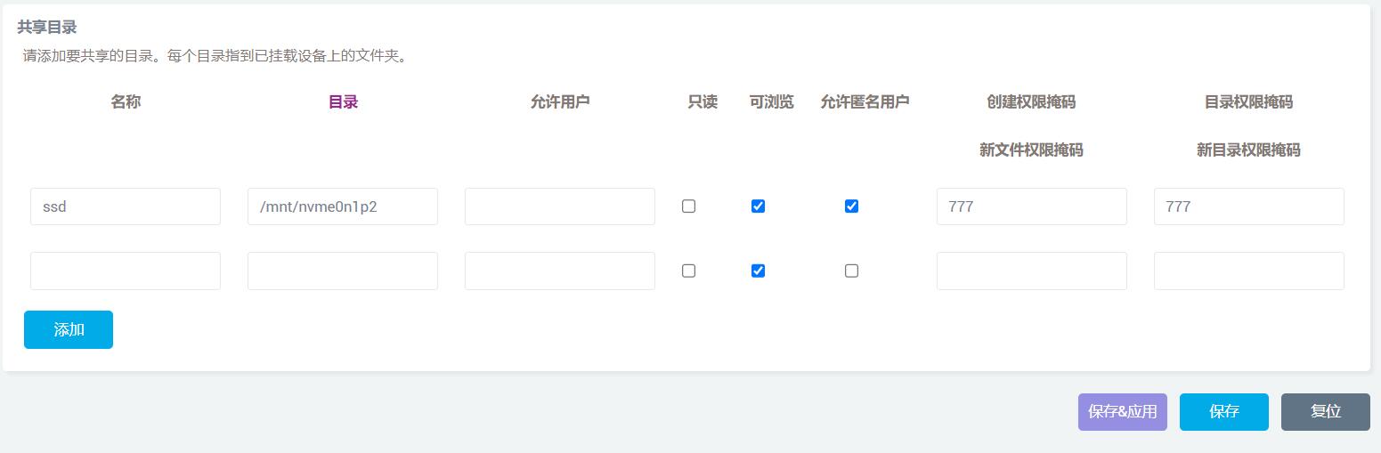
Then click the "Save & Apply" button.
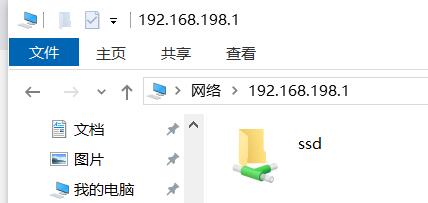
After the setup is complete, enter \\192.168.198.1 (the address is that of the extension board; it may vary in practice) in the file explorer, and you will see the shared directory.
Drag any file to the desktop to test read speed:
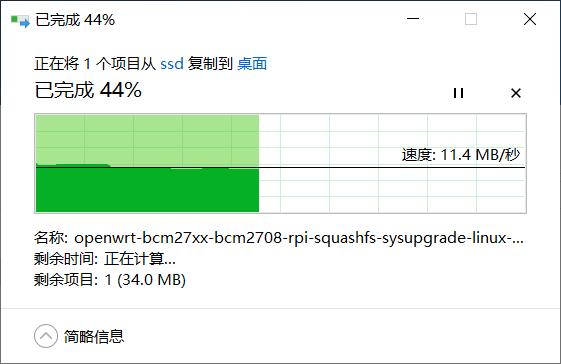
Drag and drop any file onto the SSD to test write speed:
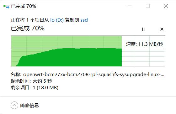
Note: Test speeds are affected by various factors such as network conditions, hard drive quality, file storage status on the drive, etc. The above test results are for reference only and do not serve as final parameters for the actual product.
If Windows prompts that access is denied when trying to access a shared resource:
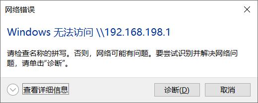
The Windows network policy needs to be modified. Press Windows + R, then type gpedit.msc to launch the Local Group Policy Editor. Go to Computer Configuration → Administrative Templates → Network → Lanman Workstation step by step. In the right content area, you can see the policy setting "Enable insecure guest logons". The status is '"Not configured".
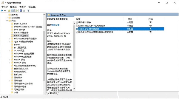
Please double-click the policy setting "Enable insecure guest logons", set its status to "Enabled," and click the OK button.
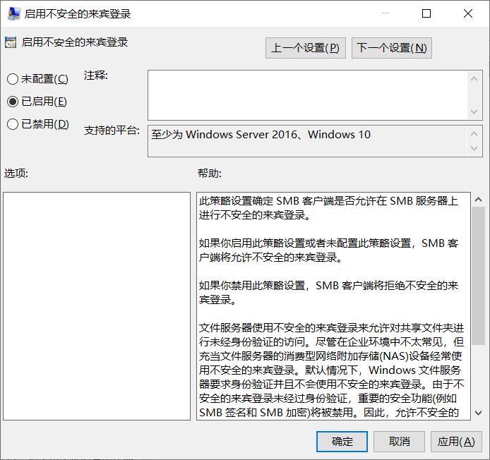
After setup, I retried and could access it successfully.
5.5 5G模块测试
Insert the 5G module (this document uses the RM500U-CN as an example) and the SIM card, then connect from the computer to the 2.5G port, leaving the native Gigabit port unconnected.
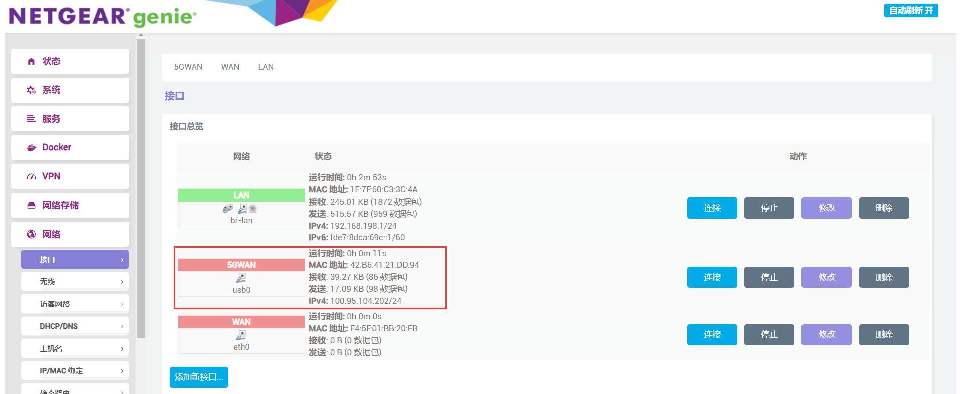
Start the system, click on "System - TTYD Terminal," log in, and enter ifconfig -a to check the network interfaces.
You can see there is a network interface named usb0, which is the 5G module, but it has no IP address.
Go to "Network → Interfaces", and click "Add new interface":
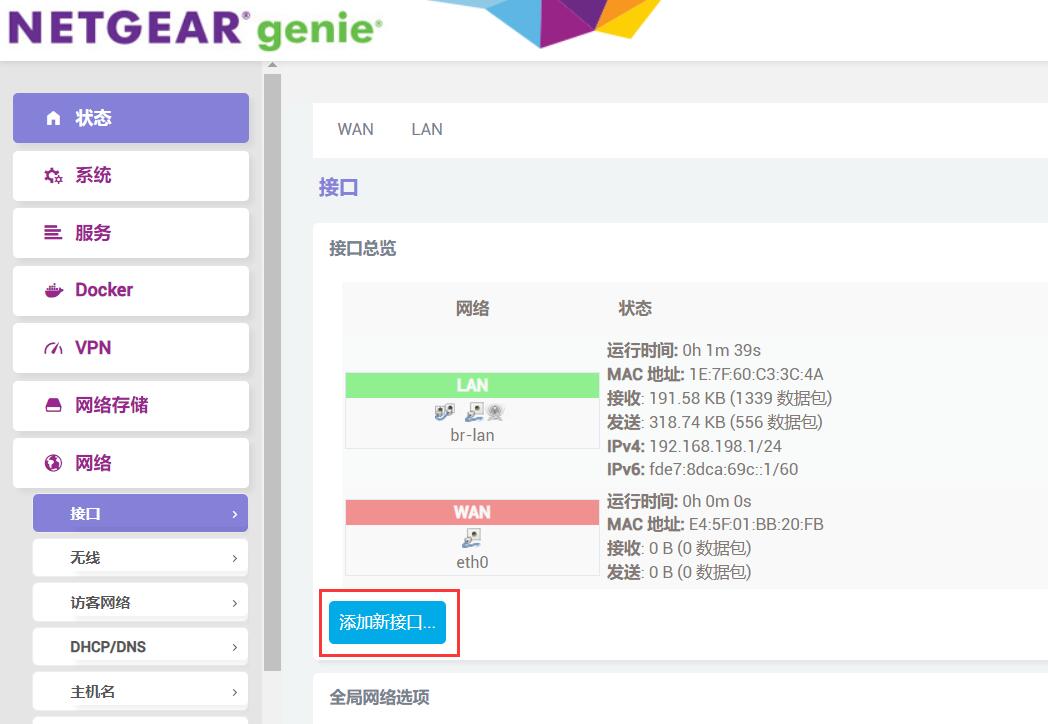
Please configure according to the diagram below to add a new interface, which this document names "5GWAN":
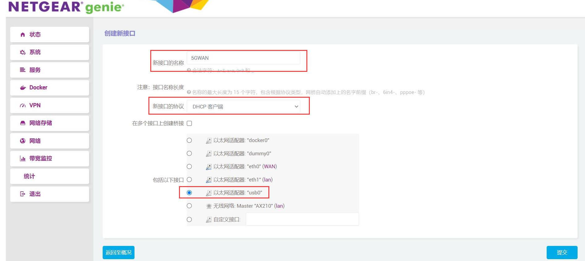
Click "Submit", then go to "Firewall Settings" and set the firewall zone to "WAN".
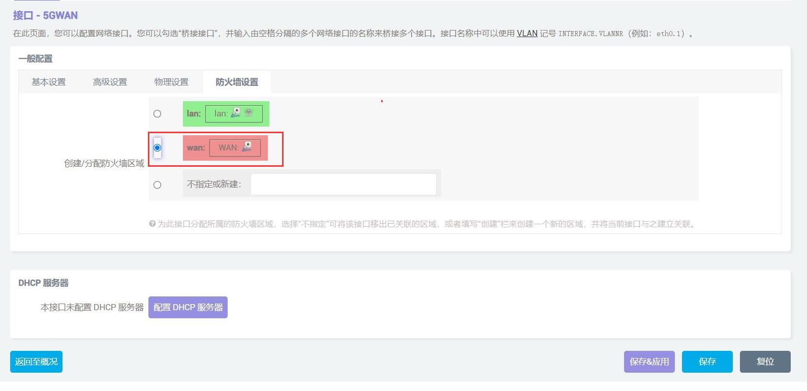
Then click "Save & Apply". After it succeeds, return to "Network - Interfaces". At this point, you will see that the 5G module has obtained an IP address, and the PC can access the internet through this 5G module.
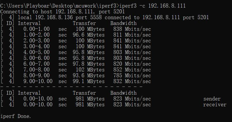
The internet speed test results on the PC are as follows:
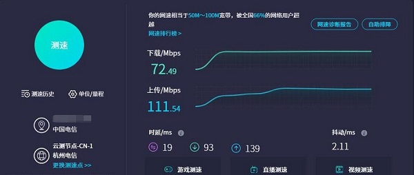
Note: Network speed test results are affected by the network environment and testing methods. The actual speed may vary, and this test is for reference only.
VI. Power consumption test information
| Standby powerconsumption | Power usage during system operation | Modules use each other | System powerconsumption | ||
|---|---|---|---|---|---|
| No external devices | 0.756A | Transferring files from the computer to the SSD over WiFi6 | 1.25A | ||
| Use 5G only | 0.9A | 1.9A (test speed) | Transferring files from the SSD to the computer over WiFi6 | 1.72A | |
| Use SSD only | 0.847A | Transferring files from the SSD to the computer over 2.5G | 1.588A | ||
| Use WiFi6 only | 0.83A | 1.15A | Transferring files from the computer to the SSD over 2.5G | 1.668A | |
| All devices connected | 1.15A | Download files from webpages to SSD over 5G | 1.88A |
Note: The above data is our company's test data and is for reference only.
Contact Us


 QQ:8204136
Email: mcuzone@vip.qq.com
Tel: +86(0)13957118045
If there are any omissions, errors, or infringements on this page, please contact us through the above methods. Thank you!
Copyright 2004-2025 Wildchip