0005 MPS2242 2280 2280P EN
Keywords
Raspberry Pi 5, 2230, 2242, 2280, Pi OS, Ubuntu, NVMe SSD, PCIe, SSD X1, Gen2, Gen3, AI、HAILO 8L, Camera, OV5647, Image Detection, Image Recognition, Optional auxiliary power supply
I. Introduction
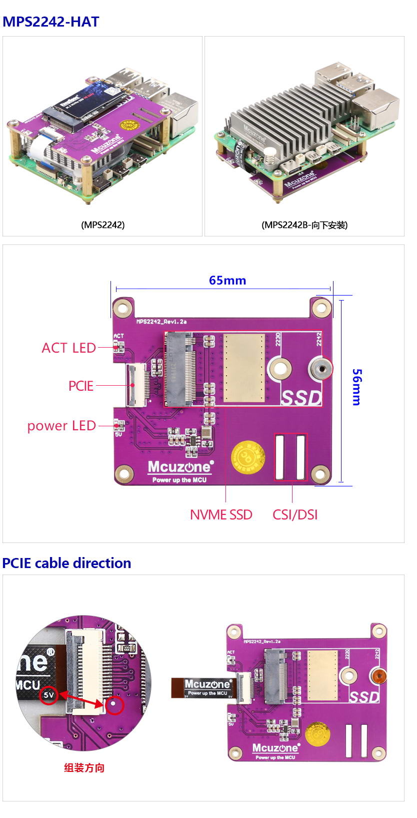
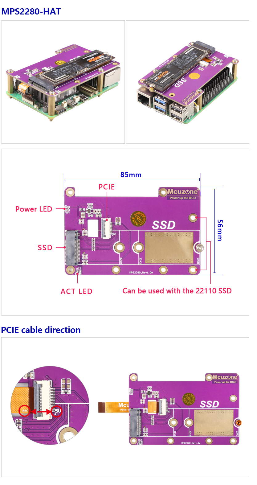
The MPS2242, MPS2280 and MPS2280P are SSD expansion boards designed for the Raspberry Pi 5 that support the NVMe protocol. The difference between there is that they support SSDs of different sizes: the MPS2242 supports 2242-sized SSDs, and the MPS2280 supports 2280-sized SSDs. The system can boot from the SSD, or it can boot from the TF card while using the SSD solely for storage purposes. The MPS2280P adds an auxiliary power supply interface for the hard drive to the MSP2280, capable of providing up to 3A of power
II. Hardware Resources
2.1 There are two versions: one for 2242 and one for 2280, the installation position is on the HAT, and both supporting NVMe protocol SSDs. Note: SSD that use the NGFF and SATA protocols are not supported.
The MPS2242 supports 2230/2242 size SSDs (defaulting to welded mounting posts for 2242 size).
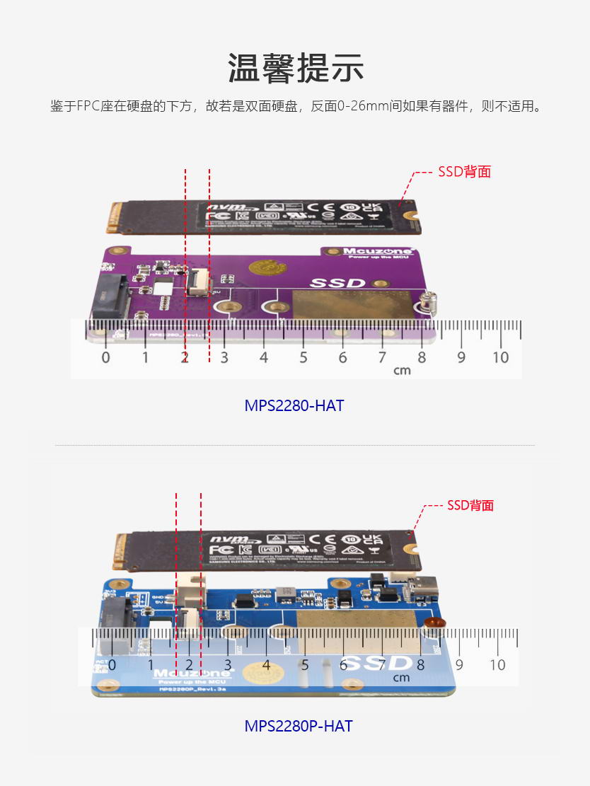
The MPS2280/MPS2280P supports 2230/2242/2280 size SSDs (defaulting to welded mounting posts for 2280 size).
2.2 It uses a 0.5mm pitch 16-pin PCIe 2.0 x1 interface for connection.
2.3 MPS2242/MPS2280 uses a 1.5A high-efficiency DC-DC circuit, which can support most SSDs (however, due to the x1 interface, the actual peak power consumption of the SSD is only one-third of its rated power consumption).
2.4 One 5V power indicator light and one hard drive activity status indicator light.
2.5 It features an indented slot design, with no obstruction above the 40-pin connector, ensuring that DuPont cable connections are not affected.
2.6 Reserve CSI/DSI cable slots.
2.7 Gold immersion PCB process, lead-free production, certified by UL, compliant with ROHS standards, and has a fire rating of 94V-0.
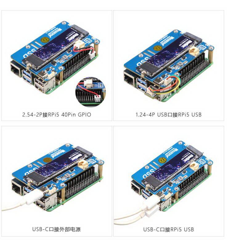
2.8 The MPS2280P uses a 3A high-efficiency DC-DC circuit. The SSD can draw power from the PCIe interface, or it can obtain 3A power through a 2.54mm 2-pin connector and a USB-C auxiliary power interface. The auxiliary power supply supports hot-swapping and meets the power requirements for most NVMe SSD.
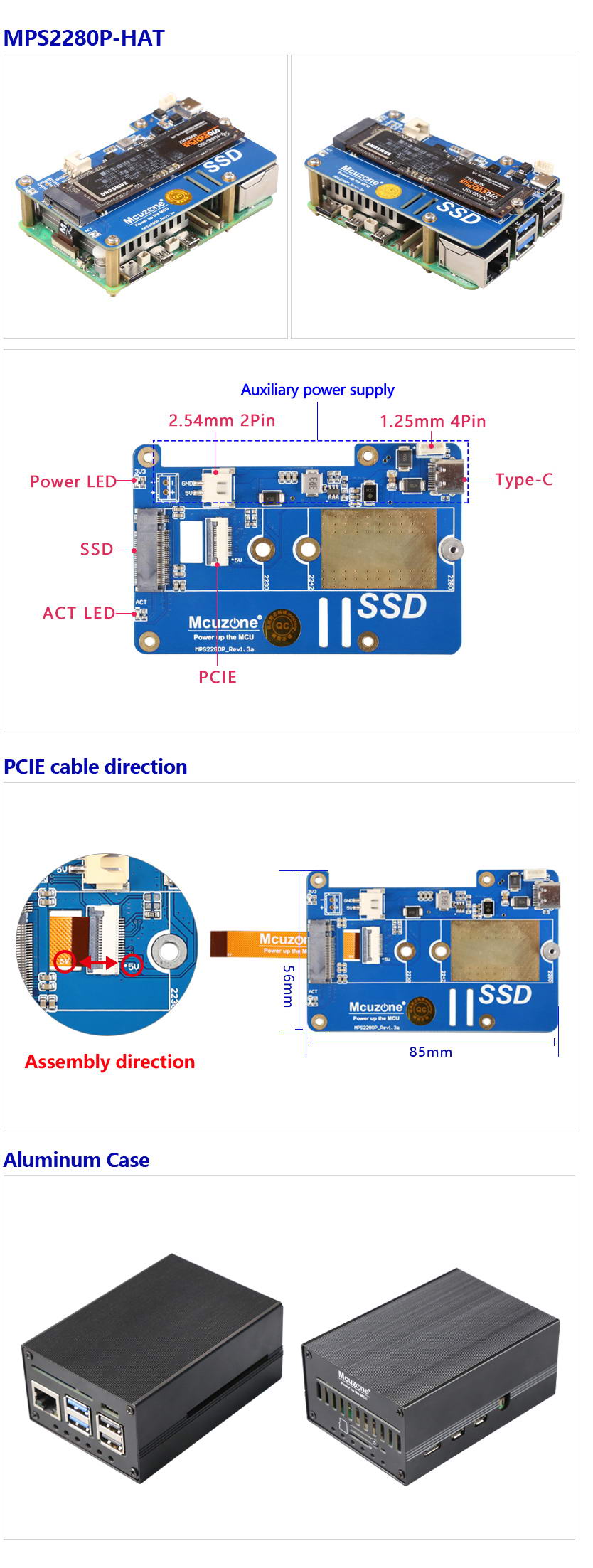
MPS2280P辅助供电:
III. System flashing and setting
3.1 Overview
This document uses the Raspberry Pi OS and Ubuntu system for testing.
The version of the Raspberry Pi OS is: 2024-07-04-raspios-bookworm-arm64.img.xz,
The version of the Ubuntu system is: ubuntu-24.04-preinstalled-desktop-arm64+raspi.img.xz。
You can download the Raspberry Pi OS in:
https://www.raspberrypi.com/software/operating-systems/#raspberry-pi-os-64-bit
You can download the Ubuntu system in:
https://ubuntu.com/download/raspberry-pi
3.2 Boot from TF card
3.2.1 Use the Imager to flash the system
First, install the Imager on the Windows. You can download it in: https://www.raspberrypi.com/software/
Insert the TF card into the card reader after installation, plug the card reader into the PC's USB port, and then open the software.
Raspberry Pi Device: Choose Raspberry Pi 5;
Operating System:
Choose Raspberry Pi OS(64-bit), to flash the system image downloaded from the Raspberry Pi official website (internet connection required).
Choose Use Custom, to flash the system image already downloaded onto the hard drive (no internet connection required).
Storage: Select the TF card that needs to be flashed (i.e., the card inserted into the PC's USB port).

After making your selections, press "NEXT". It is recommended to click "Edit Settings" to pre-configure some parameters into the flashing software. This way, you won't need to set them again during system startup, making it more convenient to use.

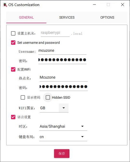
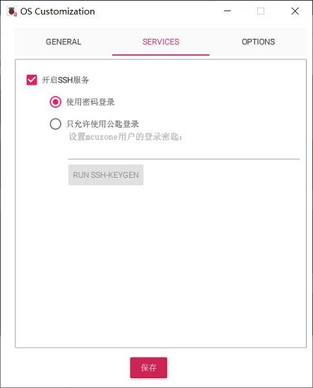
If you need to use pre-configure, press "Yes"; if you do not need to use pre-configure, press "No" to proceed to the next page.
Click "Yes" to start the burning process and verify its integrity.

The above instructions describe how to flash the Raspberry Pi OS. For flashing the Ubuntu system or the OpenWrt system, similar operations are used; when you reach the step "Operating System", you need to select Use Custom, and then choose the pre-downloaded image.
3.2.2 Use the balenaEtcher to flash the system
First, install the balenaEtcher on the Windows. You can download it in: https://etcher.balena.io/#download-etcher
Insert the TF card into the card reader after installation, plug the card reader into the PC's USB port, and then open the software.
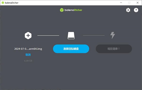
Flash from file: Select the pre-downloaded Raspberry Pi OS or Ubuntu system image.
Select target: Select the TF card that needs to be flashed (i.e., the card inserted into the PC's USB port).
Then click "Flash!" to start the process, and wait for it to complete.
3.2.3 Boot the system
Remove the TF card from the card reader, insert it into the TF card slot of the Raspberry Pi, and power the board on to enter the system.
3.3 Boot from SSD
The Raspberry Pi only supports SSDs with PCIe NVMe protocol interface.
3.3.1 Flash the Raspberry Pi OS image onto the TF card, and then boot the Raspberry Pi OS from the TF card.
3.3.2 Set the boot order and enable the SSD. Open the terminal on the Raspberry Pi OS, enter sudo rpi-eeprom-config --edit, and modify the BOOT_ORDER to:
BOOT_ORDER=0xf416
Modify or add PCIE_PROBE to:
PCIE_PROBE=1
Then press Ctrl+X, save and exit, and reboot.
Note 1: This file is saved in the E2PROM of the Raspberry Pi board after editing. Therefore, if you do not change the Raspberry Pi board and only change the system, you do not need to edit it again.
Note 2: The factory settings of the Raspberry Pi 5 vary depending on the shipment period; those shipped in 2024 have already enabled SSD booting.


The explanation for the boot order is as follows: [1]
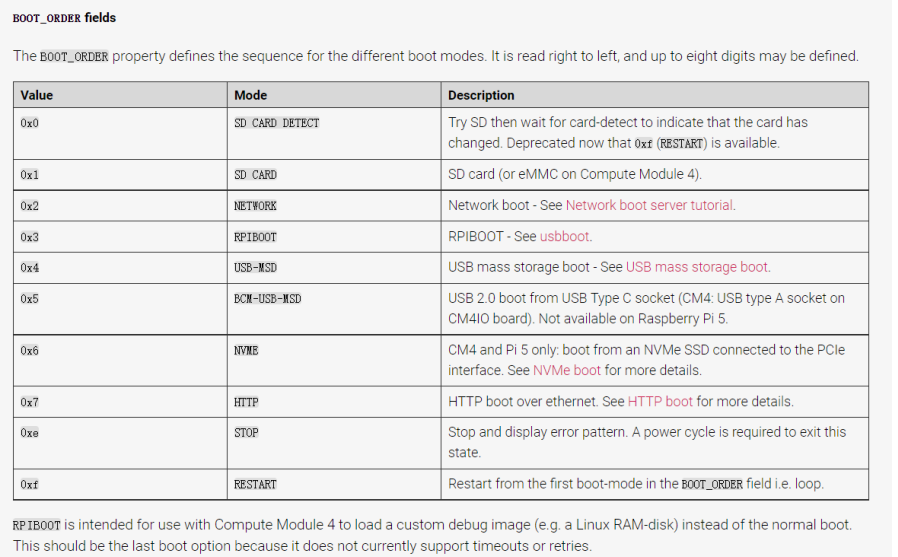
The BOOT_ORDER=0xf416 indicates the boot order is NVMe (SSD), SD (TF) card, and USB drive. You can set the boot order according to your own requirements.
3.3.3 Insert the SSD into an M.2 (PCIe NVMe protocol) to USB adapter, connect it to the PC, and use the same method as flashing an image to a TF card to flash the system image onto the SSD. Then remove the SSD, plug it back into the expansion board, and power on the system (you can remove the TF card originally used to boot the system).
3.3.4 Another method of flashing is to do it directly in the Raspberry Pi OS. You will need to prepare a USB drive and copy the Raspberry Pi OS image onto the USB drive. Set the boot order with the SD (TF) card as the first priority and the NVMe (SSD) as the second priority. Then insert the TF card with the installed system, the USB drive containing the Raspberry Pi OS installation image, and the SSD that needs to be flashed into the board.
Boot the system; at this time, the system boots from the TF card. The latest Raspberry Pi OS includes Imager. If Imager is not included in your Raspberry Pi OS, you can install it using the following command:
sudo apt install rpi-imager
Open it in the GUI:


3.3.7 In the flashing interface, select the device, OS, and storage, and start the flashing process. Note that the storage should be set to SSD at this point and not a USB drive.

During the flashing process, a prompt to enter a password will appear twice. Please enter the system login password. After the flashing process is complete, shut down the system, remove the TF card and USB drive, and restart again, it will boot from the SSD.


IV. Demonstration of using the Raspberry Pi OS
4.1 Use the SSD for storage expansion
4.1.1 Set the Raspberry Pi to boot from the TF card, insert an SSD hard drive into the M.2 slot on the expansion board, and boot the Raspberry Pi OS from the TF card.
4.1.2 In the Raspberry Pi OS, open the File Manager, and we can see the partitions of the SSD. As shown in the following figure:
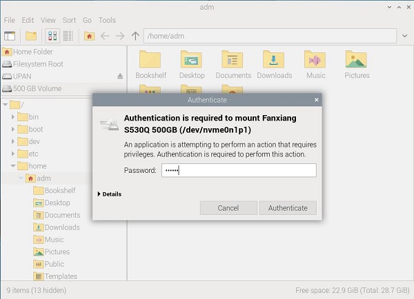
If you need to operate on the SSD, click on the partition icon. At this point, you need to enter the system password and then click "Authenticate." After successful authorization, you can proceed to operate on the SSD:
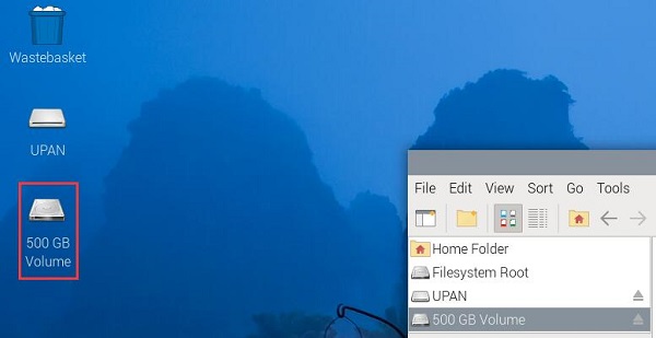
When you return to the desktop, you can see the shortcut icon for the SSD partition:
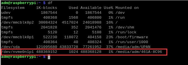
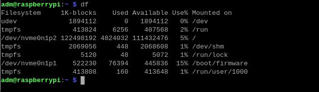
At the same time, by entering df in the terminal, we can also see the SSD partitions, and we can use this SSD as a storage device.
4.2 Use the SSD for system boot
4.2.1 Flash the Raspberry Pi OS onto the SSD, then remove the TF card, or in the boot order settings, set booting from NVMe (SSD) as the first priority.
4.2.2 Insert the SSD with the flashed system into the M.2 slot on the expansion board, and boot the Raspberry Pi OS.
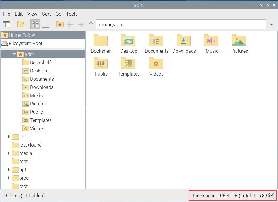
4.2.3 Open the File Manager, and we can see that the remaining space displayed in the lower right corner is 106.3GB (the total capacity of this SSD is 120GB). At the same time, by entering `df` in the terminal, you can also see that the SSD is divided into two partitions, with nvme0n1p1 used as the system partition and nvme0n1p2 used as the storage partition.
V. Demonstration of using the Ubuntu system
5.1 Use the SSD for storage expansion
5.1.1 Set the Raspberry Pi to boot from the TF card, insert an SSD hard drive into the M.2 slot on the expansion board, and boot the Ubuntu system from the TF card.
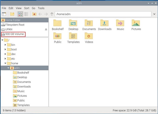
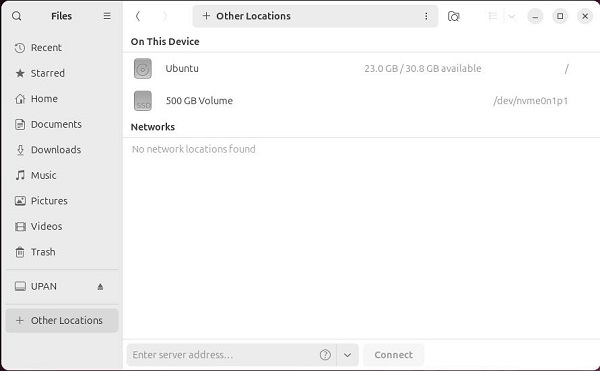
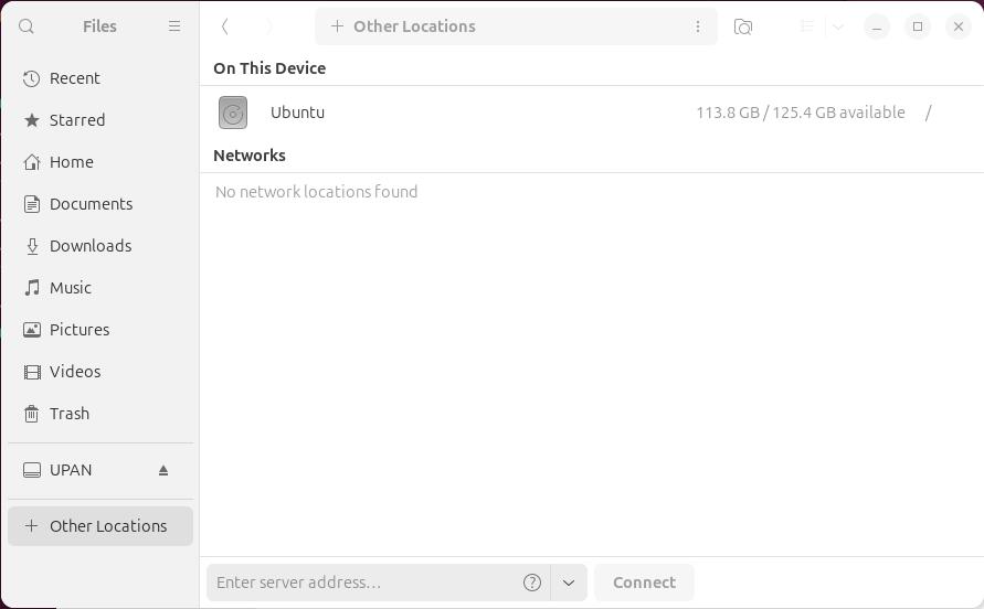
5.1.2 In the Ubuntu system, unlike the Raspberry Pi OS, we do not need to enter a system password to perform operations on the SSD. We go into Files, click on Other Locations, and we can see the SSD partition (500GB Volume, mounted to /dev/nvme0n1p1). As shown in the following figure:
Note: If you need to perform operations on the SSD in the terminal, you must enter the SSD folder following the steps above first.
5.1.3 When you return to the desktop, you can see the shortcut icon for the SSD partition:
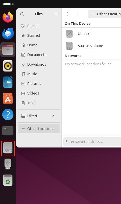
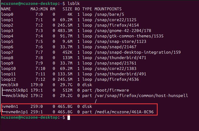
At the same time, by entering lsblk in the terminal, we can also see the SSD partitions, and we can use this SSD as a storage device.
5.2 Use the SSD for system boot
5.2.1 Flash the Ubuntu system onto the SSD, then remove the TF card, or in the boot order settings, set booting from NVMe (SSD) as the first priority.
5.2.2 Insert the SSD with the flashed system into the M.2 slot on the expansion board, and boot the Ubuntu system.
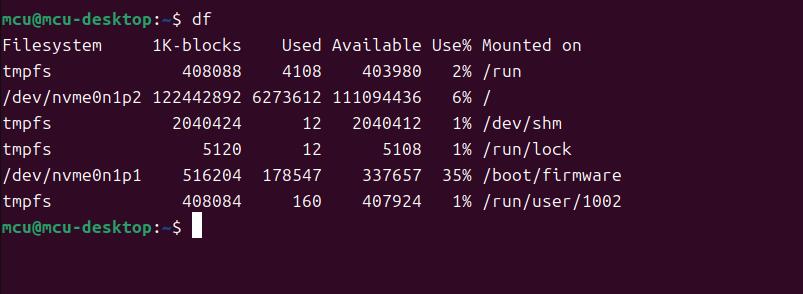
5.2.3 We go into Files, click on Other Locations, and we can see the SSD partition. Enter df in the terminal, and you can see that the SSD is divided into two partitions: nvme0n1p1 is used as the system partition, and nvme0n1p2 is used as the storage partition.
VI. Perform partitioning and other operations on the SSD
6.1 Overview
This chapter uses Raspberry Pi OS as an example to introduce operations such as partitioning and mounting an SSD installed in the MPS2242/2280.
6.2 Use the GParted to partition the SSD
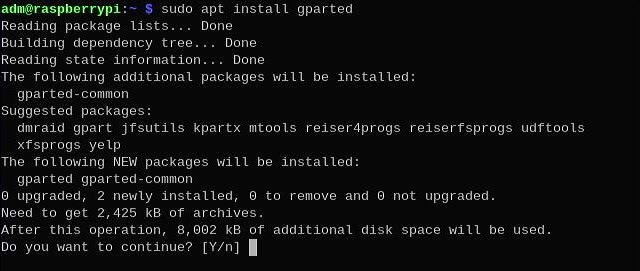
6.2.1 Open the Raspberry Pi OS terminal and enter the following command to install the GParted:
sudo apt install gparted
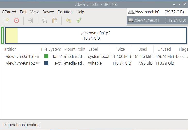
6.2.2 Open the GParted and select the corresponding SSD.
The command to open the GParted software is sudo gparted. After opening, it presents a graphical interface, and we select the SSD from the drop-down menu in the upper right corner.

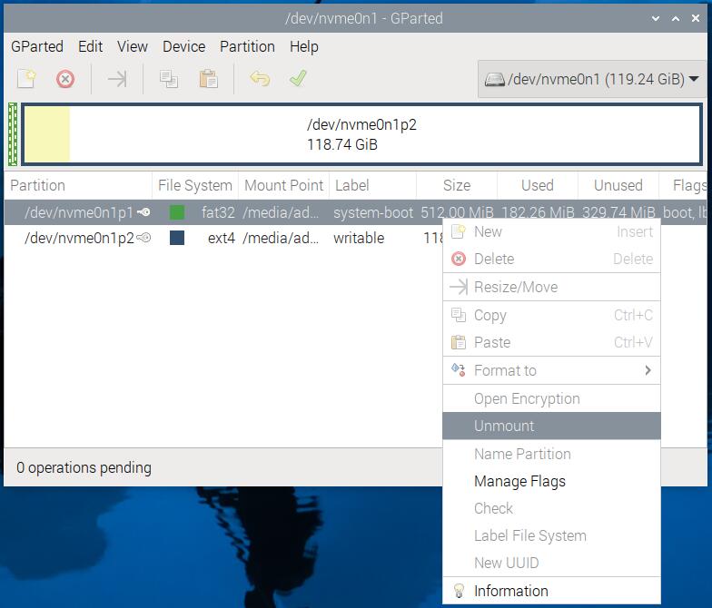
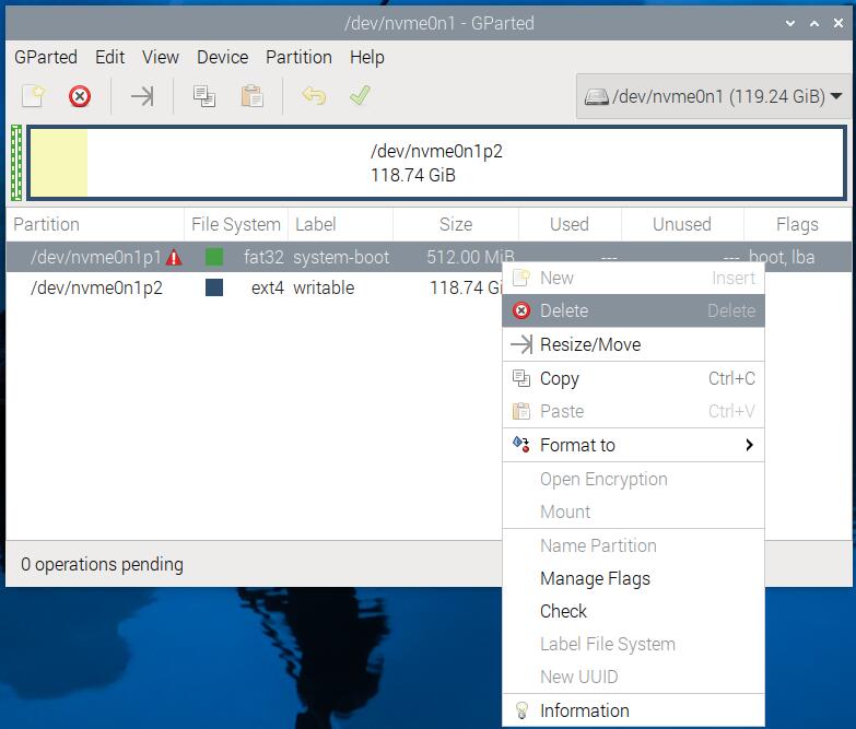
6.2.3 Before partitioning the SSD, it is necessary to unmount the original partition. Right-click on the partition and select "Unmount" to unmount it. After unmounting, right-click on the partition again and select "Delete" to delete the partition. This SSD has two partitions, and the same operation should be performed on the other partition.
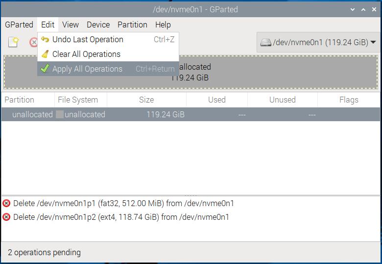
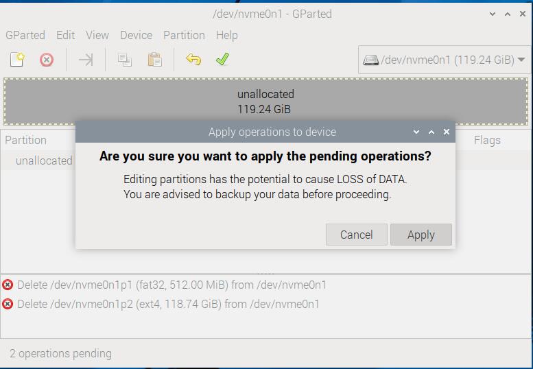
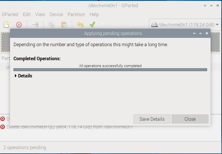
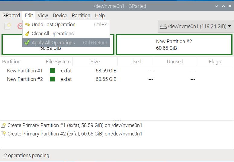
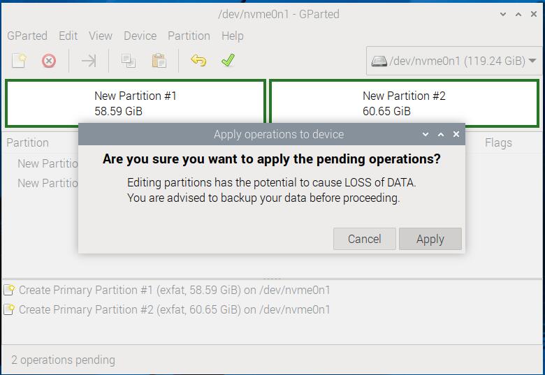
6.2.4 After deleting the partitions, we select "Edit - Apply All Operations" from the menu to apply all the operations. GParted is similar to DiskGenius, it does not perform actual operations on the partition until you apply the changes.
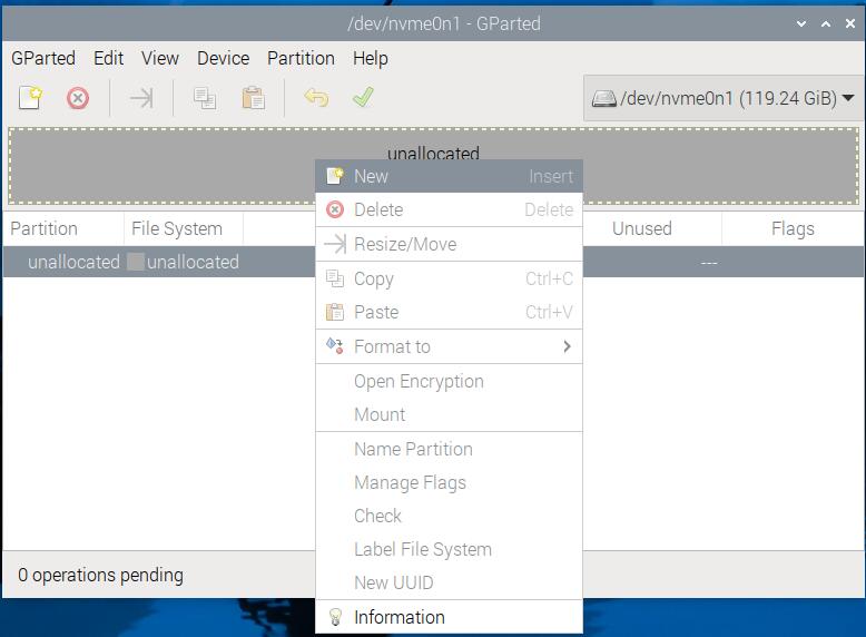
6.2.5 Then right-click on the blank SSD and select "New" to create a new partition. We created two partitions, formatted as exfat. The operations are as follows:
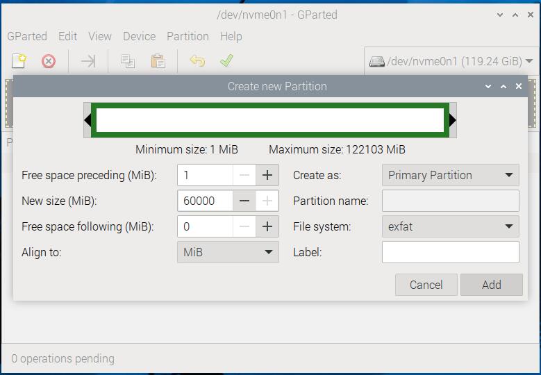
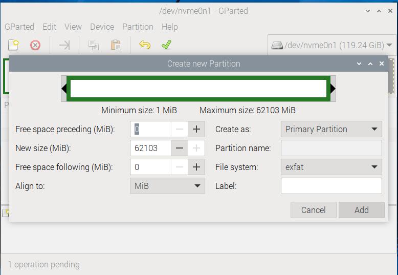
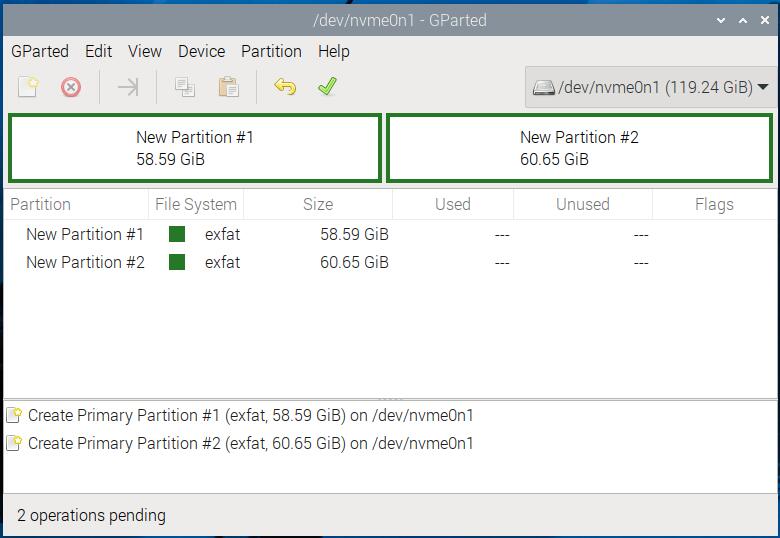
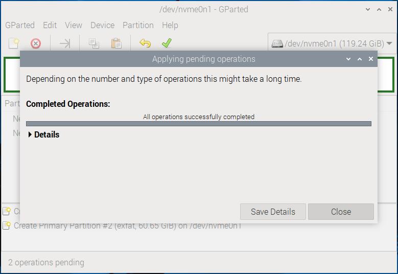
This completes the partitioning of the SSD.
6.3 Mount the partition
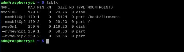
6.3.1 Now, the SSD has been divided into two partitions. These partitions can be managed under Windows, but the process differs from Linux, where the newly created partitions need to be mounted before they can be used. First, we use the command lsblk to view the partition information. The two newly created partitions' name are nvme0n1p1 and nvme0n1p2.
Then we enter the following commands in sequence to create the mount points:
sudo mkdir /ssd1
sudo mkdir /ssd2
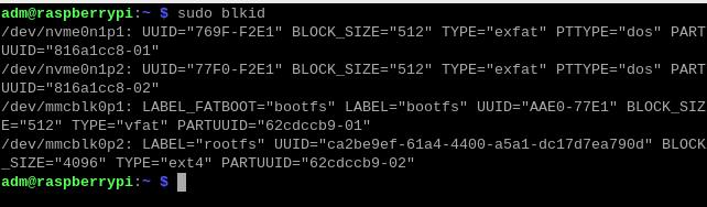
6.3.2 We enter the command sudo blkid in the terminal to view the partition UUIDs. As shown in the figure, the UUIDs of the two SSD partitions are 769F-F2E1 and 77F0-F2E1. Record these values.
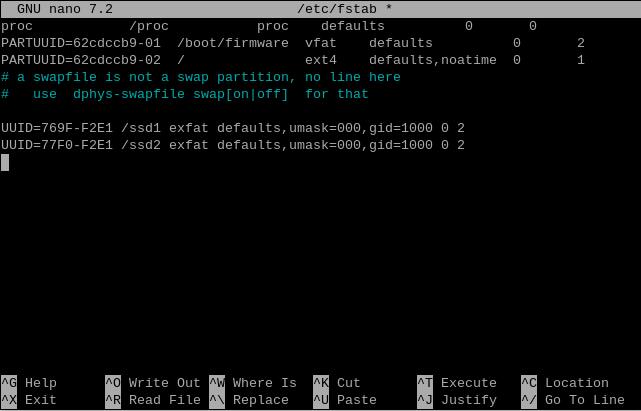
6.3.3 Enter the command sudo nano /etc/fstabin the terminal. Add two lines of code at the end of the file:
UUID=769F-F2E1 /ssd1 exfat defaults,umask=000,gid=1000 0 2
UUID=77F0-F2E1 /ssd2 exfat defaults,umask=000,gid=1000 0 2

Save and exit, then restart the system, and enter lsblk in the Raspberry Pi terminal. You can see that nvme0n1p1 and nvme0n1p2 are mounted under ssd1 and ssd2.
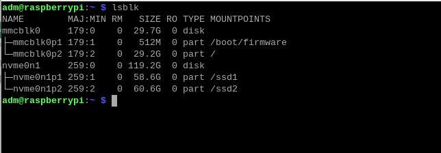
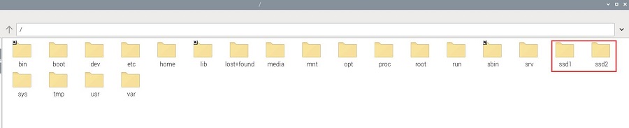
Now, we can also see two directories, ssd1 and ssd2, at the root of the file directory, each representing one of the two partitions on the SSD. We can perform operations on these two folders, thus completing the mounting of the partitions.
VII. Use hdparm to test speed of the SSD
7.1 Overview
Raspberry Pi 5 supports system operation in both PCIe Gen2 and PCIe Gen3 modes. This chapter uses Raspberry Pi OS as an example to test the SSD drive's performance under both PCIe Gen2 and PCIe Gen3 modes.
7.2 Test the SSD speed in PCIe Gen2 mode
7.2.1 The default configuration for Raspberry Pi OS is to operate in PCIe Gen2 mode, so there is no need to change the system configuration here.
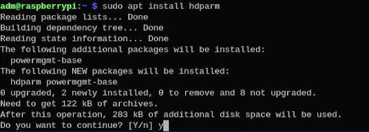
7.2.2 Install the SSD speed testing software hdparm. Enter the following command in the terminal:
sudo apt install hdparm
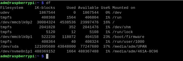
7.3.3 Run df in the terminal to check the SSD partition name, which is nvme0n1p1:
Run the command, it can be run multiple times to test the disk speed repeatedly:
sudo hdparm -t /dev/nvme0n1p1
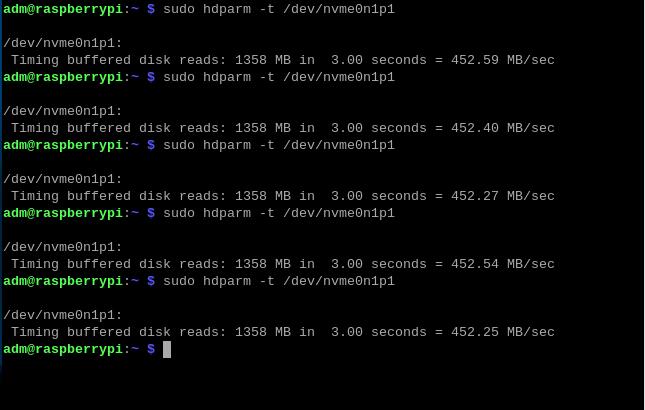
It can be seen that the test disk operates at a speed of about 450MB/s in PCIe Gen2 mode.
7.3 Test the SSD speed in PCIe Gen3 mode
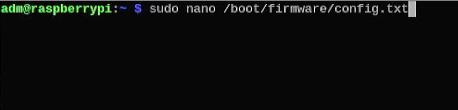
7.3.1 In the Raspberry Pi terminal, entersudo nano /boot/firmware/config.txt, and add the following line at the end:
dtparam=pciex1_gen=3
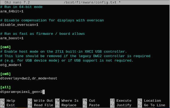
Save and exit, then restart the system; this will switch it to PCIe Gen3 mode.
7.3.2 Using the method described in the previous section, run the command, it can be run multiple times to test the disk speed repeatedly:
sudo hdparm -t /dev/nvme0n1p1
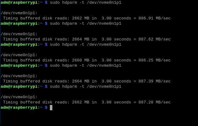
It can be seen that the test disk operates at a speed of about 880MB/s in PCIe Gen3 mode.
7.4 Conclusion
The theoretical bandwidth of PCIe Gen2 mode is 5 Gbps, and the theoretical bandwidth of PCIe Gen3 mode is 8 Gbps. Comparing the test results under PCIe Gen3 mode with those under PCIe Gen2 mode, it is evident that under PCIe Gen3 mode, due to the impact of bandwidth, the operating speed of the SSD has improved.
Note: The disk operation speed is affected by various factors, including the quality of the disk and the file storage situation on the disk. The above test results are for reference only and do not represent the final specifications of the actual product.
VIII. Demonstration of AI module (HAILO 8L) usage on the MPS2242
8.1 Overview
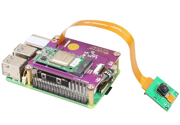
In various practical applications, the demand for camera image detection and recognition is gradually increasing, and there are many AI-based solutions available on the market. The solution demonstrated in this article involves the OV5647 camera, the MPS2242, and the HAILO 8L AI module paired with the Raspberry Pi 5.
This demonstration also applies to all Raspberry Pi 5 SSD-related PCIe adapter boards from our company, including the MPS2242-POE, MPS2280, MPS2280P, MPS2280Bi, MPS2280-POE, MPS2280D, MPS2.5G, MPSAI, MPSD2.5GD.
(Additionally, other boards with CSI interfaces and M.2 SSD interfaces on our company's Raspberry Pi CM4 expansion board can also use this solution, including the CM4_SSD expansion board, CM4_3PCIE expansion board, CM4_Ultra expansion board, CM4_SSD+WiFi expansion board, CM4_SSD+dual Ethernet, CM4_NAS.)
Note: The operation requires a stable internet connection to the regions out of China (you may need to find your own method). Otherwise, many files may not download or may only partially download, which could ultimately lead to the code failing to run.
8.2 Update system
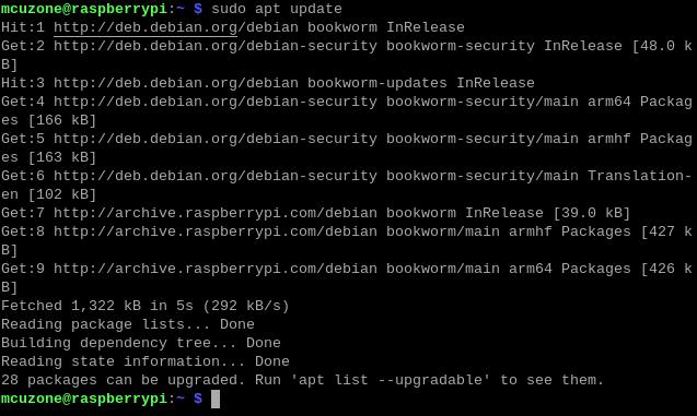
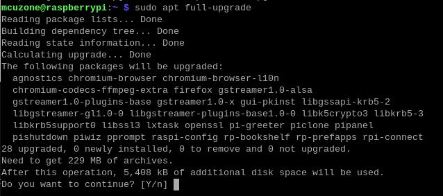
8.2.1 Boot the Raspberry Pi OS and run commands in the terminal:
sudo apt update
sudo apt full-upgrade
8.2.2 Run sudo rpi-eeprom-updateto check the Raspberry Pi firmware and ensure that the firmware date is after December 6, 2023:
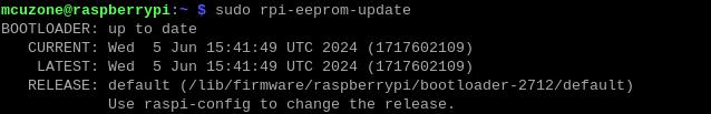
As shown in the above figure, the firmware date is June 5, 2024.
8.2.3 Run sudo raspi-config ,select the corresponding options in sequence according to the following diagram:

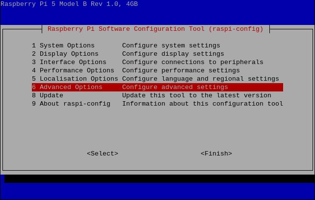
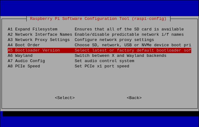
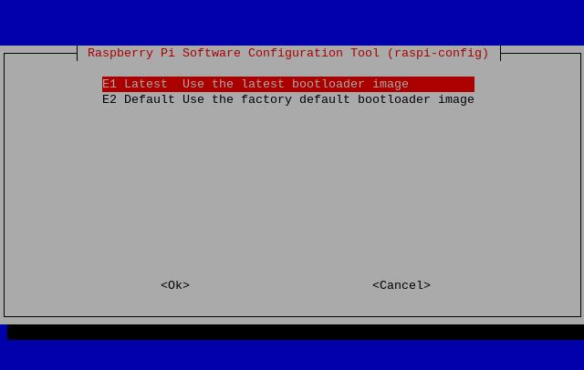
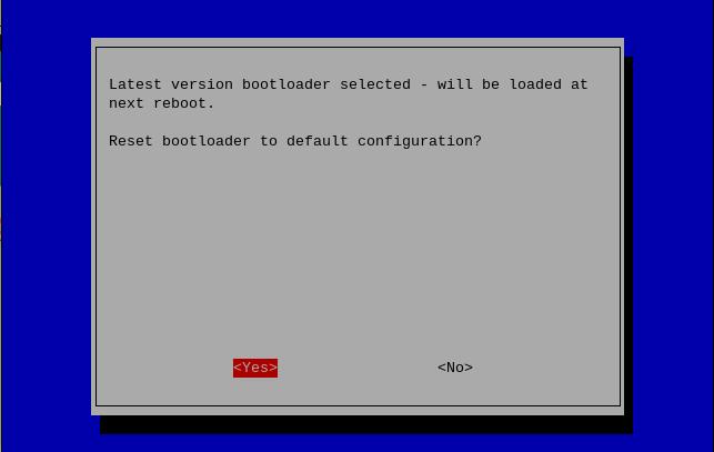
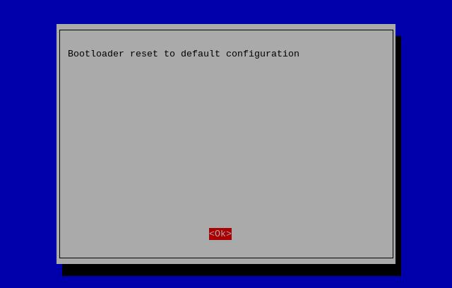
After making your selection and exiting, the system will automatically restart. If it does not restart automatically, please manually execute sudo reboot to restart the system.
8.3 Install the depends required for the AI module
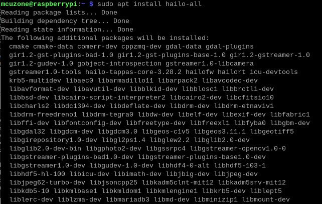
Run sudo apt install hailo-all, install the depends required for the AI module:
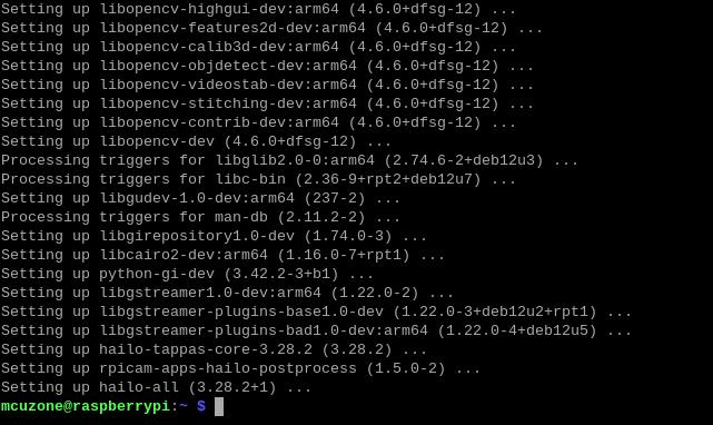
After completing this, execute sudo reboot to restart the system and apply these settings.
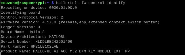
Run hailortcli fw-control identify, If the following output appears, it indicates that the depends for HAILO 8L have been successfully installed:
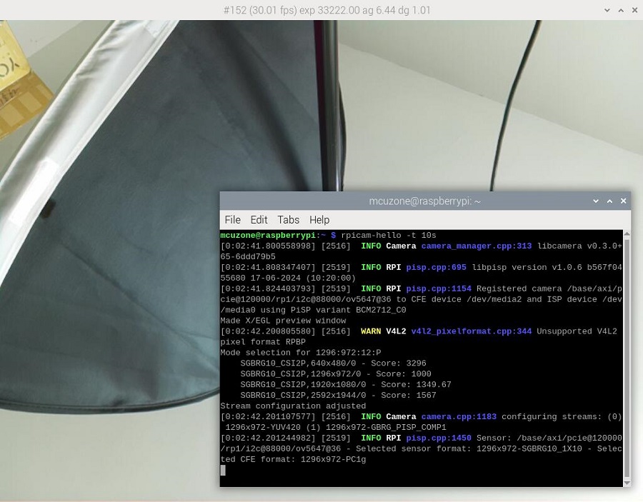
Finally, execute rpicam-hello -t 10s to turn on the camera and bring up the preview window, ensuring that the camera is functioning normally.
8.4 Image recognition and detection
Run:
git clone --depth 1 https://github.com/raspberrypi/rpicam-apps.git ~/rpicam-apps
Clone the library of rpicam-apps:
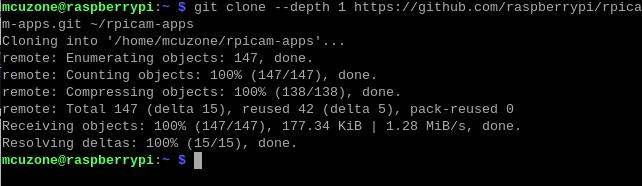
After cloning is completed, you can begin image recognition and detection:
rpicam-hello -t 0 --post-process-file ~/rpicam-apps/assets/hailo_yolov6_inference.json --lores-width 640 --lores-height 640
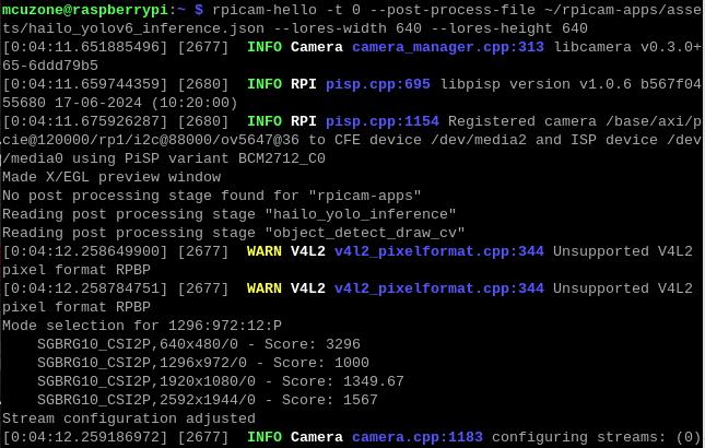
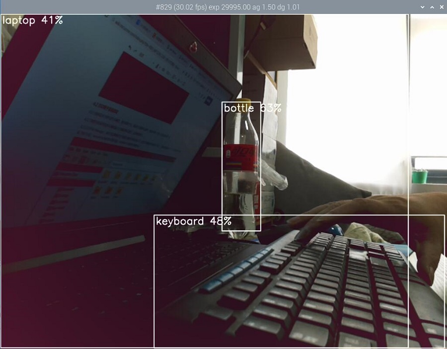
You should downloading a large amount of data from the internet out of China to use the testing of this development board, so users can contact our company after buying this development board to obtain a pre-configured Raspberry Pi OS image.
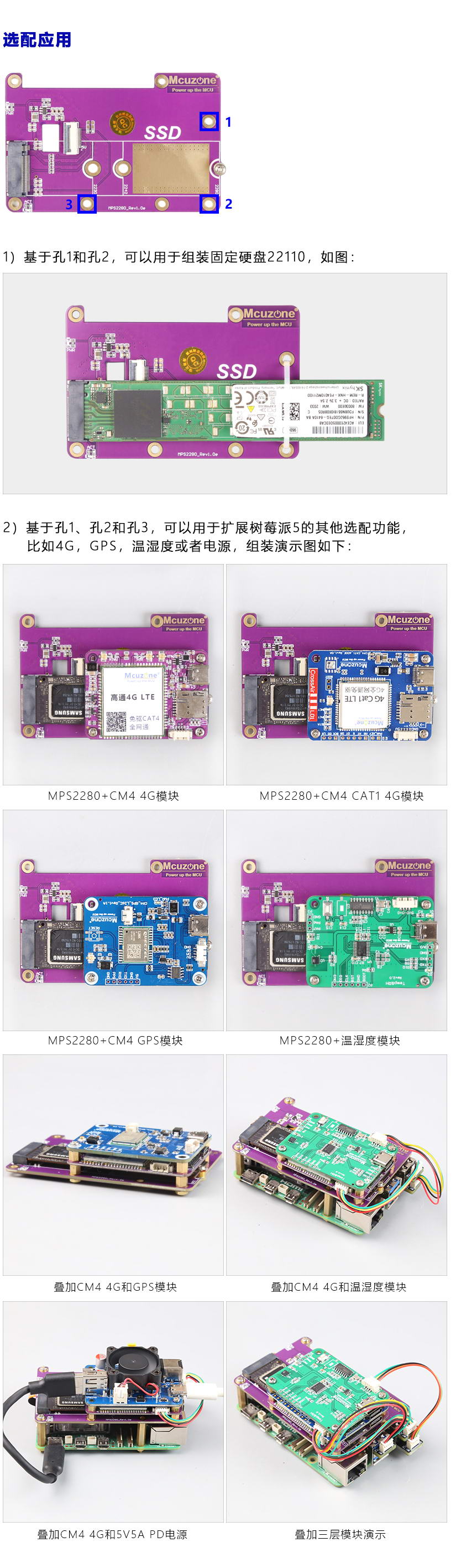
IX. Optional applications
The MPS2280 HAT has three mounting holes, and these holes can accommodate some of our CM4-sized functional modules, such as CM4 4G mini, CM4 CAT1 4G, CM4 GPS, CM4 Temperature and humidity module, CM4 4G voice module, 5V5A power supply, 5V5A PD power supply, and they can be stacked and assembled together.
The MPS2242 also has two mounting holes that can be used to assemble the CM4 4G mini module.
Contact Us


 QQ:8204136
Email: mcuzone@vip.qq.com
Tel: +86(0)13957118045
If there are any omissions, errors, or infringements on this page, please contact us through the above methods. Thank you!
Copyright 2004-2025 Wildchip
- ↑ 1