2001 RPi CM4 Ultra EN
Keywords
Raspberry, CM4 Core board, 2.5G Ethernet, NVME SSD, WiFi6, 5G, RPiOS, eMMC, OpenWrt, Video Capture
I. Introduction
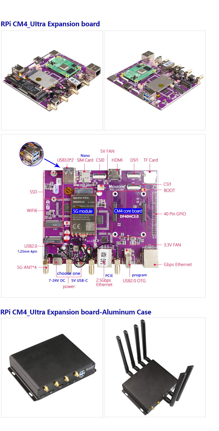
The CM4_Ultra expansion board is an expansion board designed based on the Raspberry Pi CM4 core board. It expands the single PCIe interface of the CM4 into four PCIe interfaces using a switch chip. The CM4_Ultra expansion board features one PCIe M.2 M-KEY interface for connecting an NVMe SSD, one PCIe 2.5G Ethernet port, one PCIe M.2 A-KEY interface for connecting WiFi 6, and one PCIe expansion for USB 3.0. Additionally, one of the USB 3.0 ports is connected to an M.2 B-KEY interface for external 5G expansion. The expansion board supports all versions of the Raspberry Pi CM4 core board. The expansion board is ideally suited for a variety of applications requiring high-speed data acquisition, processing, and communication, such as WiFi 6 testing terminals, remote image and video capture systems, live streaming, vehicle infotainment systems, TBOX-like vehicle data access devices, integrated media players, facial recognition, soft routers, gateways, remote image transmission, edge computing, and more.
II. Hardware Spec
| Power Supply | 1*DC input, wide voltage range of 7-24V, DC5.5-2.1 connector.
1*USB-C 5V3A port, supports PD charger; two power sources cannot be used simultaneously. |
| Nerwork | 1*native Gigabit Ethernet port.
1*PCIe 2.5G Ethernet port (RTL8125 chip). 1*PCIe M.2 A-KEY interface for expanding WiFi 6. 1*USB 3.0 M.2 B-KEY interface for connecting 5G, with a Nano SIM card slot and onboard 4 SMA antenna connectors. |
| Storage | 1*PCIe M.2 M-KEY slot, supporting 2280-sized NVMe SSD, does not support SATA/GNFF drives.
1*TF card slot, used for booting the system with the lite version of the Raspberry Pi CM4 core board; if using the CM4 core board with eMMC, this TF card slot will be unavailable. |
| USB Ports | 2*USB 3.0-A host ports.
1*USB 2.0 port, 1.25mm-4P. 1*USB OTG port (USB-A), also the programming port for the eMMC core board. |
| Display | 1*standard HDMI port supporting 4K resolution.
1*DSI1 (22PIN, 0.5mm, flip-down connection). |
| Camera | 2*CSI1(22PIN, 0.5mm, flip-down connection). |
| Others | 2*fan power supplies, 2.54mm-2P, 5V and 3.3V.
1*boot jumper, 2.54mm-2P, for flashing the eMMC core board. 40PIN GPIO, 2.54mm 20*2, fully compatible with the GPIO pins of Raspberry Pi 4B. |
| Size | 111*135mm, immersion gold process, lead-free production, PCB board certified by UL and ROHS, flame retardant rating 94V-0.
Optional aluminum alloy case with 4 fixing holes for easy equipment installation, case size: 114*154*31mm. |
The pin definitions for the 40-pin connector, from left to right:
| 5V | 5V | GND | G14 | G15 | G18 | GND | G23 | G24 | GND | G25 | G08 | G07 | IDSC | GND | G12 | GND | G16 | G20 | G21 |
| 3V3 | G02 | G03 | G04 | GND | G17 | G27 | G22 | 3V3 | G10 | G09 | G11 | GND | IDSD | G05 | G06 | G13 | G19 | G26 | GND |
III. System flashing
Raspberry Pi OS: 2024-07-04-raspios-bookworm-arm64.img.xz
You can download it in:
https://www.raspberrypi.com/software/operating-systems/#raspberry-pi-os-64-bit
3.1 Boot from TF card
If the Raspberry Pi CM4 core board does not have eMMC, the system will boot from the TF card.
Click here to the burning method instructions
3.2 Boot from eMMC
If the Raspberry Pi CM4 core board has onboard eMMC, it can only boot from the eMMC, and the onboard TF card will be ineffective.
First, you need to install the driver package for the Raspberry Pi CM4 core board on your PC. You can download it from the official Raspberry Pi website or from our company's website:
http://www.mcuzone.com/down/Software.asp?ID=10000623
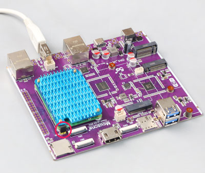
Then, use a jumper cap to short the BOOT pin and the GND pin, and connect the USB 2.0 OTG interface on the expansion board to the computer using a USB Type-A cable (as shown in the figure below):
After connecting to the computer, open the Device Manager, and a new USB device will appear. In the image below, the USB device is named "BCM2711 Boot".

Under the All Programs section of the PC's Start menu, there is an rpiboot under Raspberry Pi.

Open this software, and the computer will format and partition the eMMC or TF card.

Wait a moment, and a partition will appear in the file explorer (in this example, the partition is named bootfs, but the actual name may var

Next, we can use the balenaEtcher to flash the image to this partition.
Please open the balenaEtcher software, click on the first option "Flash from file," and select the file you want to flash to the eMMC. For the second option, choose the bootfs partition mentioned above, then click "Flash now" to start the flashing process.


After the burning process is completed, we need to remove the previously inserted short-circuit cap (otherwise the core board will not start properly), then power it on again to boot the system.
IV. Work with Raspberry Pi OS
4.1 Ethernet test
4.1.1 Ethernet connection
Connect the gigabit Ethernet port to the upstream router, and execute ifconfig -a on the terminal, which displays the following:
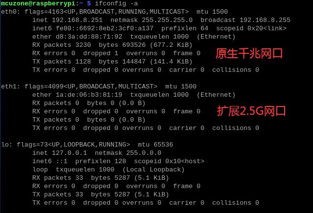
eth0 is a native Gigabit network card and has obtained an IP address.
eth1 is an extended 2.5G network card, but since no network cable is plugged in, it has not acquired an IP address.
4.1.2 2.5G Ethernet speed test
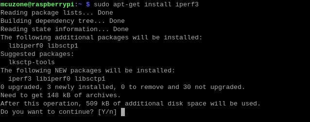
We plug the Ethernet cable into the 2.5G port, and the system will automatically obtain an IP address. Then, we open the terminal and install the speed-testing tool iperf3.
sudo apt-get install iperf3
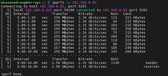
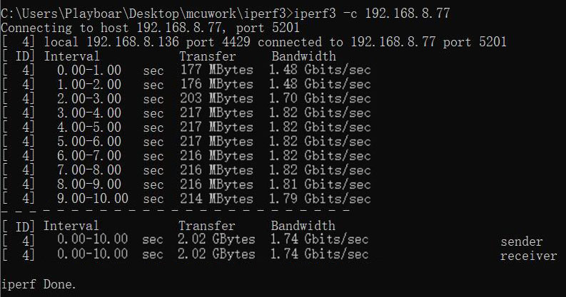
2.5G Ethernet speed test results:
2.15Gbps (client mode).
1.75Gbps (server mode).
Note: The speed test results of 2.5G networks are affected by network conditions and testing methods. The actual speed may vary, and this test is for reference only.
4.1.3 Gigabit Ethernet speed test
We plug the network cable into the native Gigabit Ethernet port, and the system will automatically obtain an IP address. Then, we open the terminal and test using iperf3.
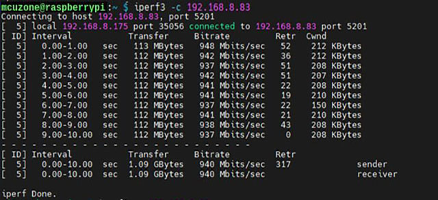
Native Gigabit Ethernet speed test results:
940Mb/s (client mode).
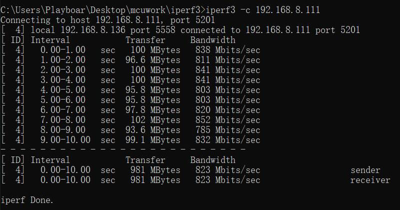
Note: The speed test results of 2.5G networks are affected by network conditions and testing methods. The actual speed may vary, and this test is for reference only.
4.2 SSD Hard drive testing
4.2.1 Basic operations of SSD drives
NVMe SSDs are for data storage only and cannot be used as a system boot drive.
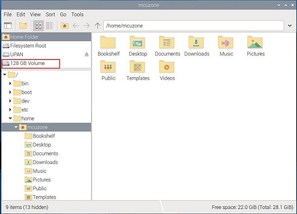
In Raspberry Pi OS, when you open the File Manager, you can see the partitions of the SSD. The screenshot is shown below:
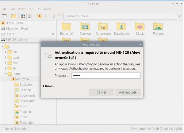
To operate the SSD, click the partition icon, enter the system password, and then click "Authenticate". After successful authorization, you can perform operations on the SSD.
Now, when you return to the desktop, you will see the shortcut icon for the SSD partition.
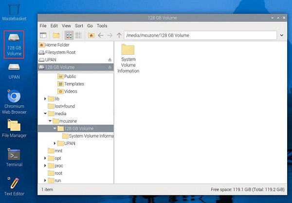
You can also enter df in the terminal to see the SSD partition and its mounting information. We can use this SSD as a storage device.

If you need to perform operations such as partitioning and permanently mounting an SSD, please refer to this page.
4.2.2 SSD speed test
4.2.2.1 SSD interface speed test
We use the hdparm to test the SSD drive interface speed.
Install the hdparm software:
sudo apt install hdparm
Run the command multiple times to test the SSD speed repeatedly.
sudo hdparm -t /dev/nvme0n1
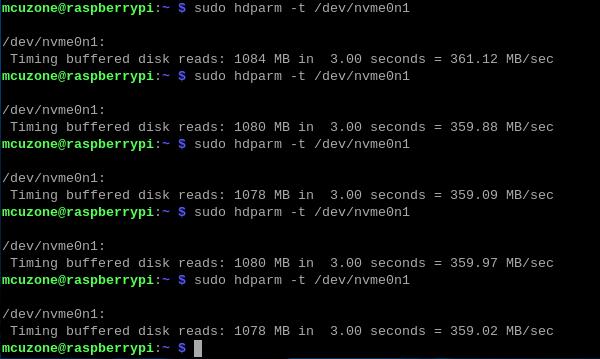
测试结果:该硬盘的接口速度为360MB/s左右。
4.2.2.2 Install the SAMBA file sharing service
SAMBA is a software for sharing files between Windows and Linux. We can use it to transfer files between Windows and Raspberry Pi via Ethernet, which allows us to test network speed.
Install SAMBA:
sudo apt install samba
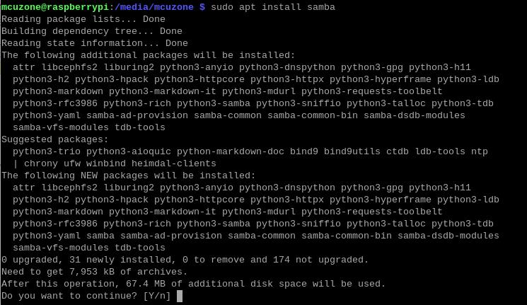
Create a new folder under the SSD path for sharing files and modify the folder permissions.
cd /media/mcuzone/writable
sudo mkdir ssdfiles
sudo chmod +777 ssdfiles

Modify the SAMBA configuration file to add a shared node.
sudo mousepad /etc/samba/smb.conf
Add the shared node at the end of the file:
[ssd]
# Shared folder instruction
comment = ssd
# Shared Folder Directory
path = /media/mcuzone/writable/ssdfiles/
# Mount path of the shared directory that needs to be mapped
browseable = yes
# Resource name publicly visible (content hidden, set to 'Yes')"
writable = yes
# Writable
create mask = 0777
# New files are created with 777 permissions.
directory mask = 0777
# New files are created with 777 permissions.
public = no
# Guest access without a password (set to "No" here)
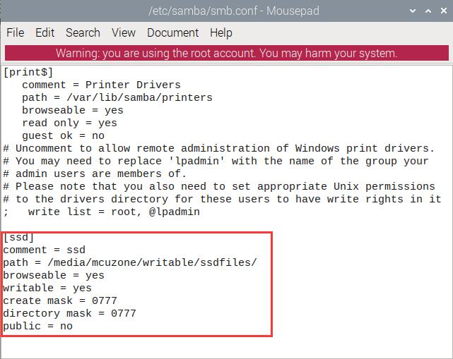
Note: If you need to add more mapped folders, please continue adding new shared nodes in the same format, ensuring that the shared folder description and shared folder directory are not duplicated. The local path should be filled in according to the mounted path.
Create a user named mcuzone1; you will be prompted to set a password afterward.
sudo smbpasswd -a mcuzone

Restart SAMBA:
sudo systemctl restart smbd

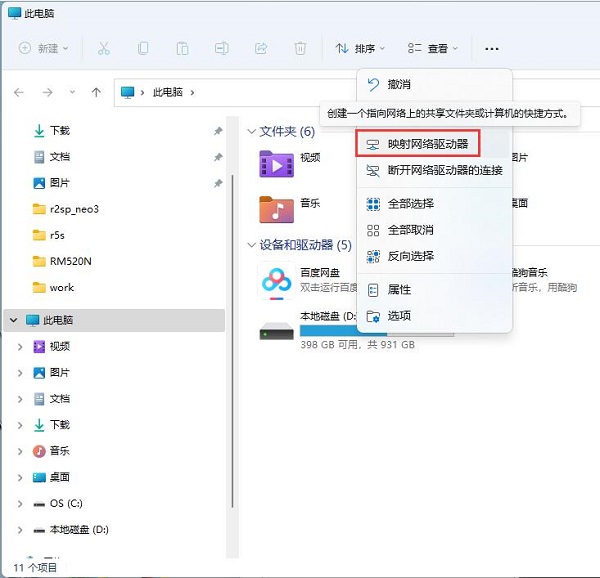
Then, map a network drive in Windows, using Windows 11 as an example here.
Open "This PC", then click "Map network drive".
Fill in the relevant node information according to the diagram below (the IP is the Raspberry Pi OS IP):
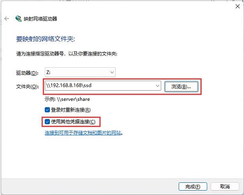
Enter the username and password you just set:
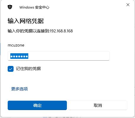
Then, the shared folder that was set up was opened.

Note: Before setting up a shared folder, you must grant permission to the SSD partition in the Raspberry Pi OS. Otherwise, you will encounter a "network name not found" error when configuring the shared folder.
4.2.2.3 SSD R/W testing over a Gigabit Ethernet port
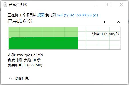
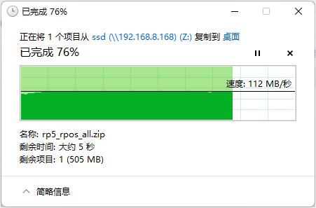
Connect the network cable to the Gigabit Ethernet port, then conduct R/W speed tests on the SSD drive via the SAMBA file sharing service.
Write:
Read:
4.2.2.4 SSD R/W testing over a 2.5G Ethernet port
将网线插在2.5G网口上,利用SAMBA文件共享服务,对SSD硬盘进行读写测试。
写:
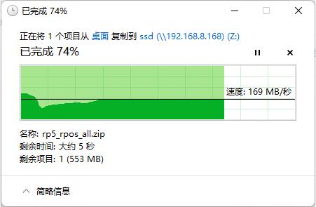
Connect the network cable to the 2.5G Ethernet port, then conduct R/W speed tests on the SSD drive via the SAMBA file sharing service.
Write:
Read:
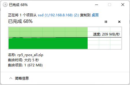
Note: The speed of the SSD drive test is influenced by various factors such as network conditions, hard drive quality, file storage status, and OS environment. The above test results are for reference only and should not be considered as the final parameters of the actual product. In practical tests, the read speed can reach up to 270MB/s.
4.3 DSI test
The official Gen 1 Raspberry Pi LCD screen needs separate power and requires an adapter board and DSI-compatible expansion board.
After connecting, power on the board. Wait for the OS to run, then open the terminal and execute the following commands
sudo nano /boot/firmware/config.txt

Add the following statements at the end of the file:
dtoverlay=vc4-kms-dsi-7inch
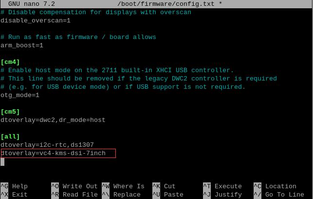
After saving, restart the OS to use the official Raspberry Pi 7-inch touchscreen.
Upon restart, execute the following commands in the terminal in order.
wget http://www.mcuzone.com/wiki/2001_CM4_Ultra/Brightness.zip
unzip Brightness.zip
cd Brightness
sudo chmod +x install.sh
./install.sh
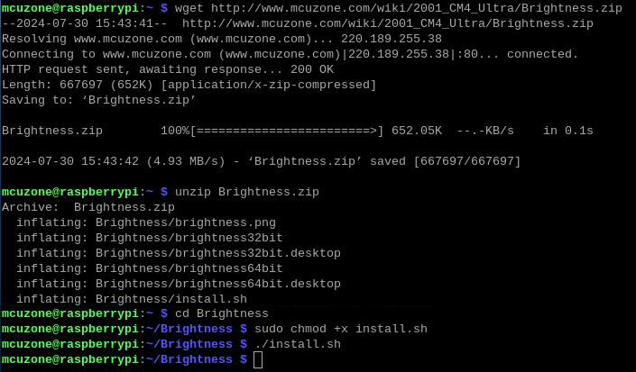
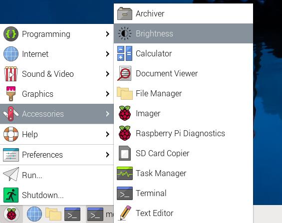
Then you can open the Brightness window from the Accessories menu to adjust the backlight of the 7-inch screen.

4.4 CSI test
We tested using the OV5467 camera, connecting it to either the CSI0 or CSI1 interface. After connecting, power on the board, open the terminal, and execute the following commands:
sudo nano /boot/firmware/config.txt

Add the following statements at the end of the file:
dtoverlay=ov5647,cam0
dtoverlay=ov5647,cam1
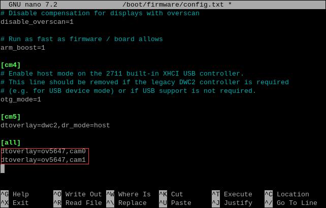
In actual use, add the configuration according to your model, save the changes, and then restart the system to enable the OV5647 camera.
After rebooting, execute the following command in the terminal:
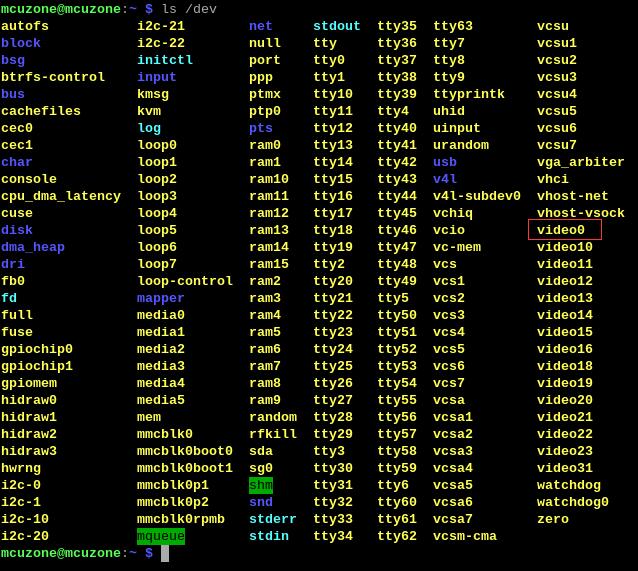
ls /dev
You can then see the video0 and video1 devices (inserting one camera displays video0, inserting two cameras displays video0 and video1, regardless of whether they are connected to CSI0 or CSI1).
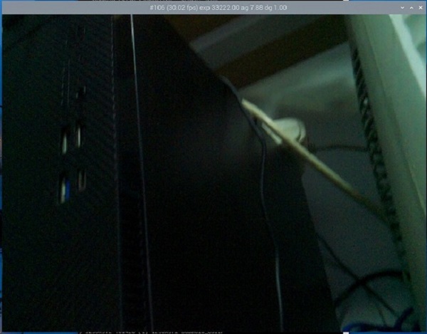
To preview the camera feed, execute libcamera-hello --camera 0 or libcamera-hello --camera 1 in the terminal (a single connected camera is camera 0, while two cameras are assigned as camera 0 and camera 1).

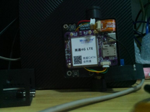
If a photo is required, please execute:
libcamera-jpeg -o test.jpg

Save the photo in the /home/mcuzone directory (i.e., the user's home directory). The photo effect is as follows:
4.5 USB test
系统启动后我们将无线键鼠插入OTG接口,两个USB3.0 SD读卡器插入USB3.0接口,输入lsusb查看USB设备:

Bus 002 Device 003:USB3.0-A,USB3.0 SD读卡器;
Bus 002 Device 004:USB3.0-A,USB3.0 SD读卡器;
Bus 003 Device 002:USB2.0-A(OTG)接口,接无线键鼠。
识别都正常;随后输入lsusb -t查看USB口的工作模式是否正常。

Bus 02:为5000M USB口(USB 3.0);
Bus 03:为480M USB口(USB 2.0);
工作模式都正常。
4.6 5G模块测试
测试基于移远5G模组RM500U-CN,我们已经将5G模组配置好了,在树莓派官方OS下免驱,自动识别。
(如果用户自己的5G模组,需要用户自己配置或者自己整驱动,不然无法实现免驱的,无法参考此章节)
4.6.1 5G测试
树莓派OS的终端,输入命令ifconfig -a,可以看到如下网络信息:
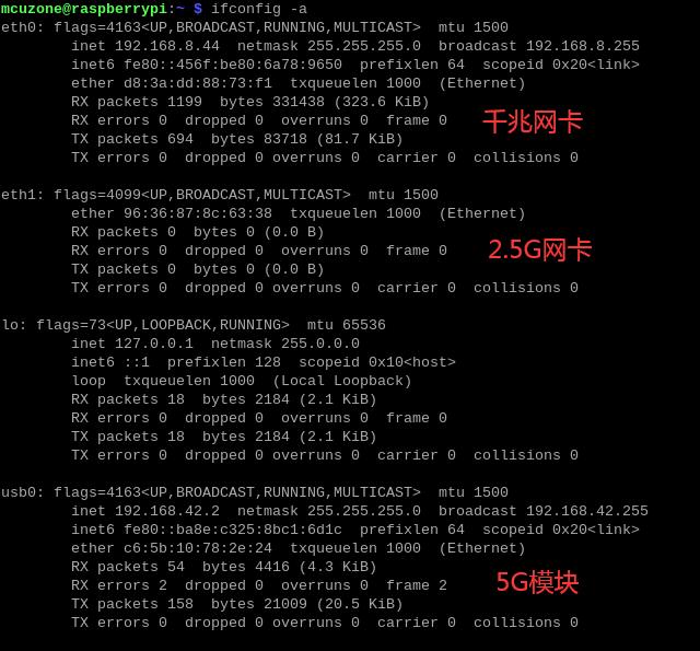
从上图可知,此时千兆有线网卡和5G模组均已获取了ip,我们ping网址成功:

但是如果拔掉网线,则ping IP能通,但ping域名不通,如下图所示:
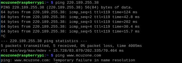
因此需要查看下系统的nameserver(即DNS服务器)是否正确。通过下面的命令打开resolv.conf文件:
sudo nano /etc/resolv.conf

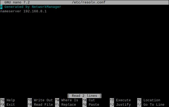
查看此时的nameserver是否正确,如果不正确,请将其改为sim卡的nameserver(通常是其网关地址)或者一些通用的nameserver地址(如114.114.114.114等)。
不过,这种修改方式在系统重启后,resolv.conf文件内的DNS会被修改到默认地址,所以如果需要开机自动启动5G上网,还需要修改resolv.conf文件的权限,因为/etc/resolv.conf实际上是个软链接,所以需要重新生成resolv.conf文件才能修改权限,方法如下:
sudo mv /etc/resolv.conf /etc/resolv.conf.link
sudo nano /etc/resolv.conf
这样就重新建立了resolv.conf文件,在这个新建的文件中输入:
nameserver 114.114.114.114
保存退出,然后执行:
sudo chattr +i /etc/resolv.conf
做完上述步骤后,重启系统,resolv.conf文件的内容也不会变化了。
4.6.2 网络优先级的修改
如果同时插了网线和5G模块,默认情况下,优先通过5G网络上网。
执行route命令,查看路由表,usb0排在第一位,因此此时是通过5G模块上网:

如果要优先使用有线网络上网的话,可以运行命令:
sudo ip route del default && sudo route add -net default netmask 0.0.0.0 gw 192.168.8.1
这两条命令(以“&&”分隔)的解释:
sudo ip route del default:删除路由表中的默认路由;
sudo route add -net default netmask 0.0.0.0 gw 192.168.8.1:添加有线网络的网关为新的默认路由(网关地址以实际为准)。
执行完毕后,再执行route,查看路由表,目前的默认路由为有线网络的网关(eth0排第一位):

这样网络就默认走有线网络了,如果需要改回默认走5G网络,请运行:
sudo ip route del default && sudo route add -net default netmask 0.0.0.0 gw 192.168.42.1
或者重启系统即可。
其中192.168.42.1为5G模组的默认网关,请以实际为准。
注意,重启后路由表还是会恢复原状,所以如果重启后要网络继续默认走有线网络,需要再执行一次sudo ip route del default && sudo route add -net default netmask 0.0.0.0 gw 192.168.8.1。
4.6.3 5G网络网速测试
我们拔掉网线,只剩下5G网络连接,进入测速网站进行测速。
结果如下:
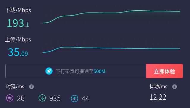
注意:5G模块网络测速受5G信号和测试方法影响,速度请以实际为准,本测试仅供参考。
4.6.4 AT命令的使用
将5G模块接入扩展板,系统启动后,我们输入lsusb,显示如下:

记下5G模块的ID:2c7c 0900。
下载minicom工具:
sudo apt-get install minicom

使用下列命令打开ttyUSB串口,其中echo后面的值就是上面记录的ID值:
sudo modprobe option
sudo sh -c 'echo 2c7c 0900 > /sys/bus/usb-serial/drivers/option1/new_id'

执行下面命令,进入AT命令:
sudo minicom -D /dev/ttyUSB2

进入minicom后我们输入AT命令进行测试:
如果需要查看回显,请键入命令:ate1,然后回车,继续键入其它命令,回车可以看到结果。
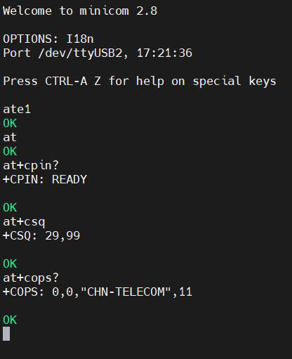
常用AT命令:
1. 检查SIM卡是否识别到:
at+cpin?
返回ready表示卡已识别,返回error要检查硬件
2. 检查天线信号质量:
at+CESQ
3. 检查注网情况:
at+cops?
正常应该返回运营商代码和一个数字,7代表4G,11代表5G。
注意,以上命令只有at+CESQ不要加问号,另外两条命令需要加问号。
4. 查看5G模块的IMEI码:
at+cgsn
5. 关闭射频:
at+cfun=0
开启射频:
at+cfun=1
上述两条命令成对使用,可以在不重启5G模组的情况下让模组重新注网。
6. 切换SIM卡
使用SIM1(丝印标识):
AT+QUIMSLOT=1
使用SIM2(丝印标识):
AT+QUIMSLOT=2
切换时如果原来的卡槽有卡,Windows会提示卡弹出,请将模块断电,把卡插到另一个卡槽,然后重新上电;如果切换过去的卡槽有卡,则可直接使用。
7. USB口和以太网口不可同时使用,可以通过AT命令切换:
使用USB口:
AT+QMAPWAC=0
使用以太网口:
AT+QMAPWAC=1
4.7 WiFi6测试
树莓派CM4支持WiFi6(AX200)和WiFi6E(AX210)模块,都需要安装驱动才能使用。驱动的安装步骤如下:
4.7.1 安装驱动
首先要更新系统和头文件,打开树莓派终端,输入sudo apt-get update,更新系统:

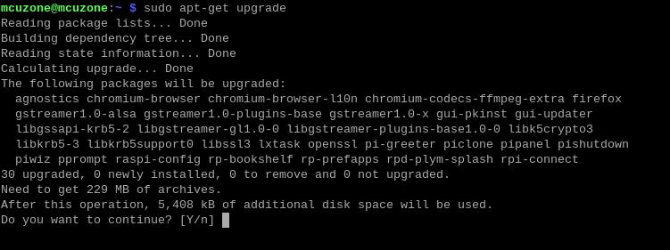
然后输入sudo apt-get upgrade:
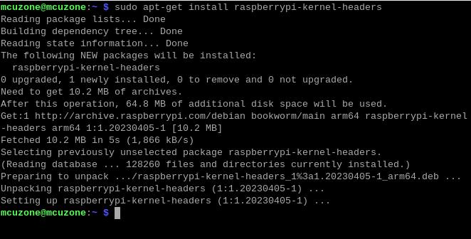
最后输入sudo apt-get install raspberrypi-kernel-headers安装头文件:
把wifi驱动源码下载至本地,输入:
git clone https://git.kernel.org/pub/scm/linux/kernel/git/iwlwifi/backport-iwlwifi.git

下载完成后,cd backport-iwlwifi进入源码文件夹,输入make defconfig-iwlwifi-public,输出.config配置文件:

输入:
sed -i 's/CPTCFG_IWLMVM_VENDOR_CMDS=y/# CPTCFG_IWLMVM_VENDOR_CMDS is not set/' .config

输入make -j4,此处-j4表示用四核进行编译,如果出现死机卡死的情况,可以尝试用-j1或者-j2进行编译:

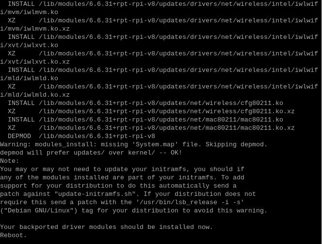
编译完成后,输入sudo make install进行驱动安装:

安装完毕后提示重启,请先不要重启。
4.7.2 安装固件
不同的模组,固件不一样,我们这里用的是AX210.
依次在树莓派终端执行:
cd ..
cd Downloads
wget http://www.mcuzone.com/wiki/2001_CM4_Ultra/iwlwifi-ty-a0-gf-a0-59.zip
unzip iwlwifi-ty-a0-gf-a0-59.zip
sudo cp iwlwifi-ty-a0-gf-a0-59.ucode /lib/firmware
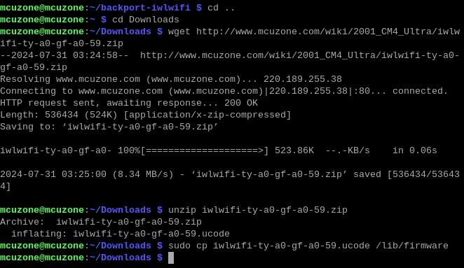
然后输入cd /lib/firmware,再输入ls /lib/firmware iwl*.*,若有iwlwifi-ty-a0-gf-a0-59.ucode这个文件,即表明固件安装成功:

4.7.3 测试WiFi6模块
固件安装完成后,重启系统,点击桌面右上角网络图标,然后点击“Click here to set Wi-Fi country”:

我们选择CN:

再次重启系统,然后在桌面右上角手动连接WiFi,输入密码:
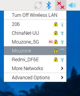
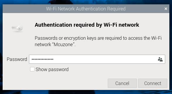
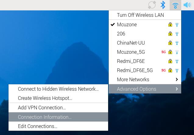
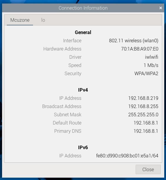
显示WiFi成功连接后,查看网络参数:
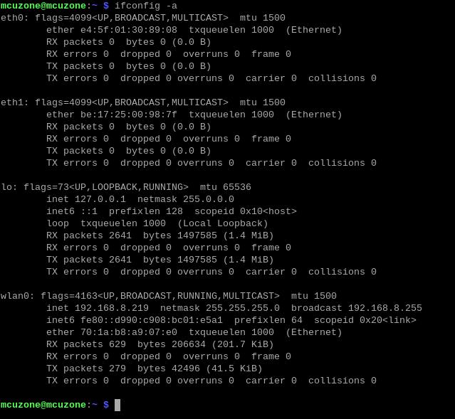
在树莓派终端执行ifconfig -a,也可以查看网络参数(wlan0):
五、OpenWrt系统操作
我们测试使用的OpenWrt系统版本为:openwrt-bcm27xx-bcm2711-rpi-4-squashfs-sysupgrade-linux-6.1.98-20240723.img.gz 此系统已经包含wifi6驱动和我们公司配套5G模组驱动。
CM4_Ultra扩展板在OpenWrt系统下可配置为一进一出的交换机模式,扩展板上的原生千兆口作为WAN口(连接Internet),2.5G网口配置为LAN口,用于连接PC。
5.1 登录系统
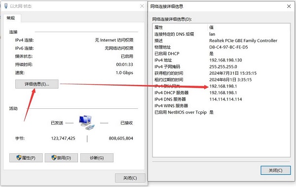
将扩展板上的原生千兆口连接网线至PC网口,系统上电启动后,我们在Windows设置中找到网络和Internet,在以太网中打开连接的网络查看默认网关的IP地址,这个地址就是OpenWrt系统的后台配置页面地址,如图所示,本文测试的地址为192.168.198.1:
然后打开网页浏览器输入192.168.198.1进入OpenWrt系统。默认用户名为root,默认密码为password:

5.2 设置网络接口
打开“网络 - 接口”,点击“添加新接口”:

接口名称设置为“WAN”,接口协议选择“DHCP客户端”,接口选择“eth0”后点击“提交”按钮:

在防火墙设置中选择WAN口后点击“保存”按钮。注意不要点“保存&应用”按钮:
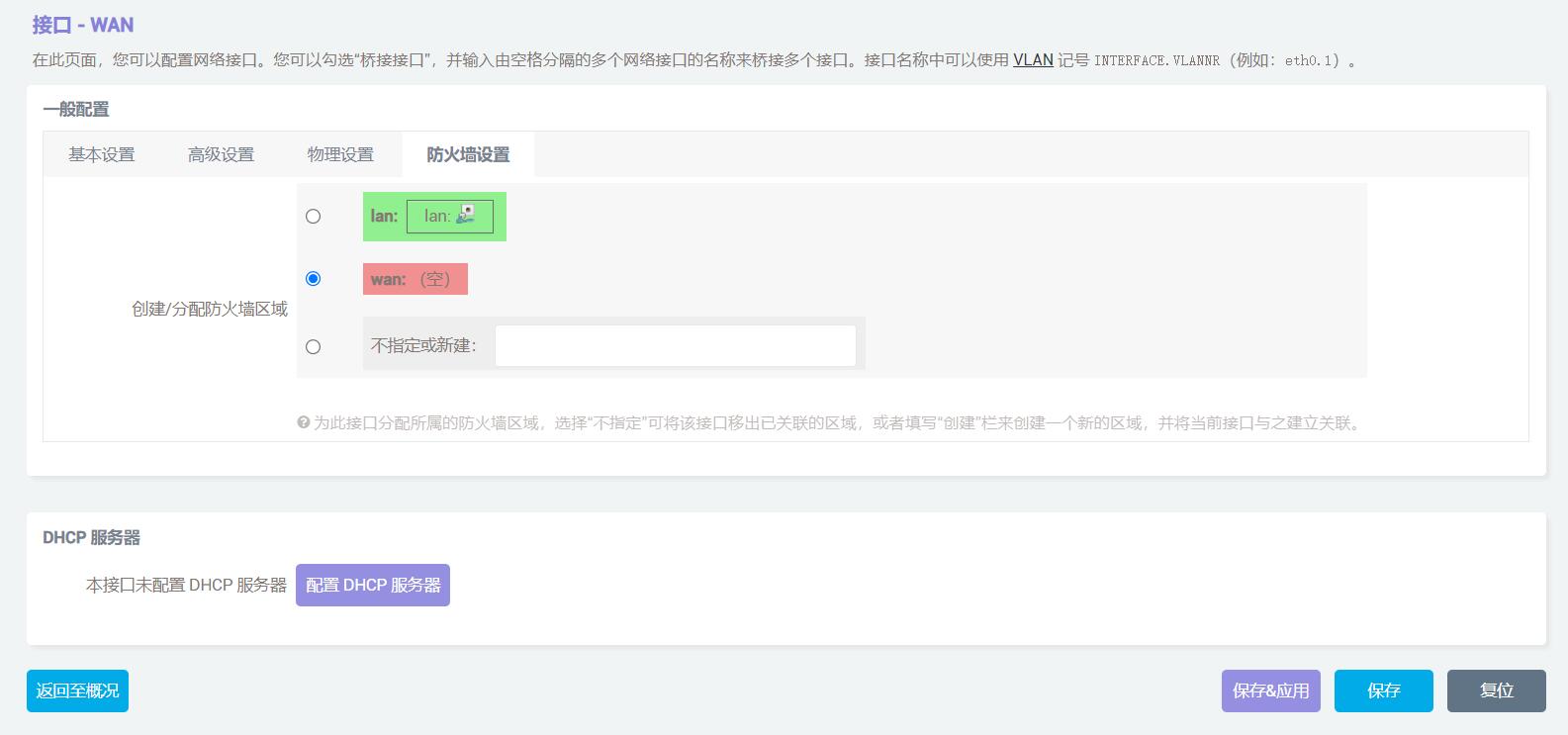
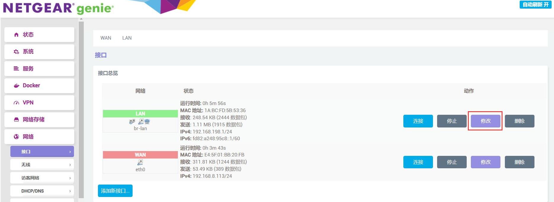
然后点击“返回至概况”按钮,在接口处点击LAN口的“修改”按钮:

在物理设置中将接口改为eth1:
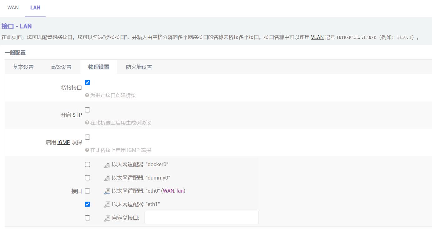
随后点击“保存&应用”按钮,网络配置就完成了。
5.3 2.5G网口测试
网络配置完成后,原生千兆网口就变成了WAN口,2.5G网口就变成了LAN口,将与电脑连接的网线切换到2.5G网口,再将原生千兆网口接到上级路由器。进入OpenWrt页面,点击“系统-TTYD终端”,登录后(默认用户名为root,默认密码为password)输入ifconfig -a查看IP地址:
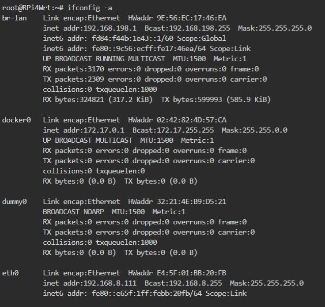
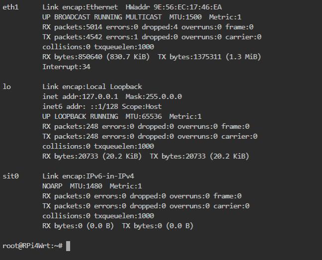
其中eth0是2.5G网卡,eth1千兆网卡。
也可以在“网络 - 接口”查看网口信息:
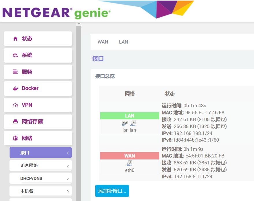
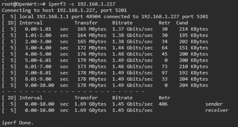
接下来我们在TTYD终端使用iperf3测速软件(系统自带),与PC之间进行测速:
扩展板作为client时:
扩展板作为server时:
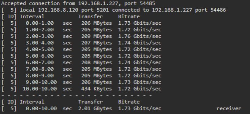
注意:网络测速受网络环境和测试方法影响,速度请以实际为准,本测试仅供参考。
5.4 SSD硬盘测试
登录后台页面后,进入“系统 - 挂载点”,我们可以看到SSD硬盘已经被自动挂载:

点击“网络存储-网络共享”,注意有可能会有两个“网络共享”,要进标注Samba的网络共享,而不是Ksmbd的网络共享!
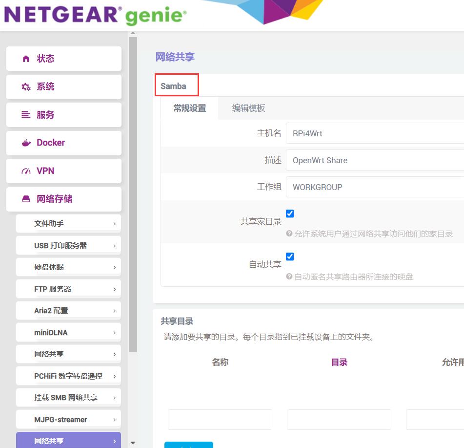
添加一个共享目录,目录为硬盘挂载的地址:

随后点击“保存&应用”按钮。
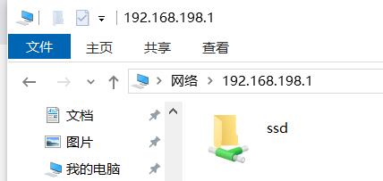
设置完毕后在资源管理器中输入\\192.168.198.1(地址为扩展板的地址,视实际情况而不同),我们就能看到那个共享目录了:
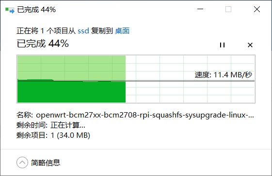
将任意文件拖拽到桌面进行读取速度测试:
将任意文件拖拽到SSD进行写入速度测试:
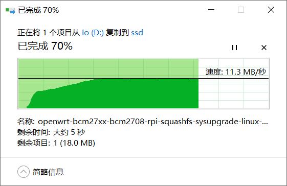
注意:测试速度受网络状况、硬盘质量、硬盘上的文件存储情况等多种因素影响,以上测试结果仅供参考,不作为实际产品的最终参数。
如果在访问共享时Windows提示无法访问:
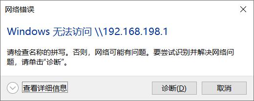
需要修改Windows网络策略。按window+R键输入gpedit.msc 来启动本地组策略编辑器。依次找到“计算机配置 - 管理模板 - 网络 - Lanman工作站”这个节点,在右侧内容区可以看到“启用不安全的来宾登录”这一条策略设置。状态是“未配置”:
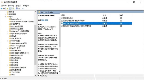
双击“启用不安全的来宾登录”这一条策略设置,将其状态修改为“已启用”并单击确定按钮:
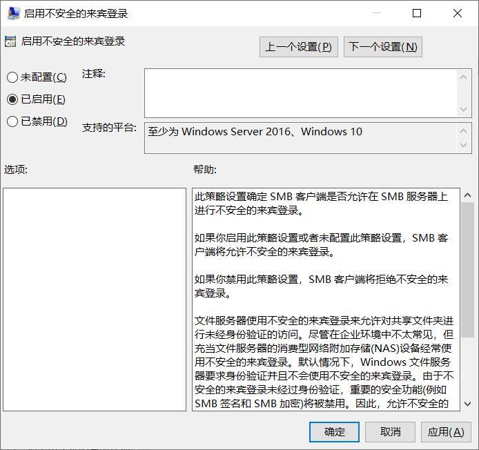
设置完成再次尝试访问发现可以正常访问了。
5.5 WiFi6模块测试
5.5.1 设置WiFi6
承接5.2章节之后,将WiFi6模块(AX200或AX210)插上扩展板,2.5G网口连电脑,千兆网口不插网线。登录后台后,在“网络 - 无线”中可以看到无线概况:
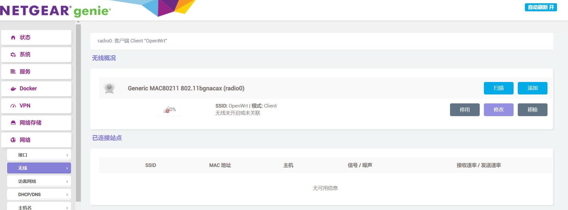
点击“扫描”按钮,扫描出附近的无线AP:
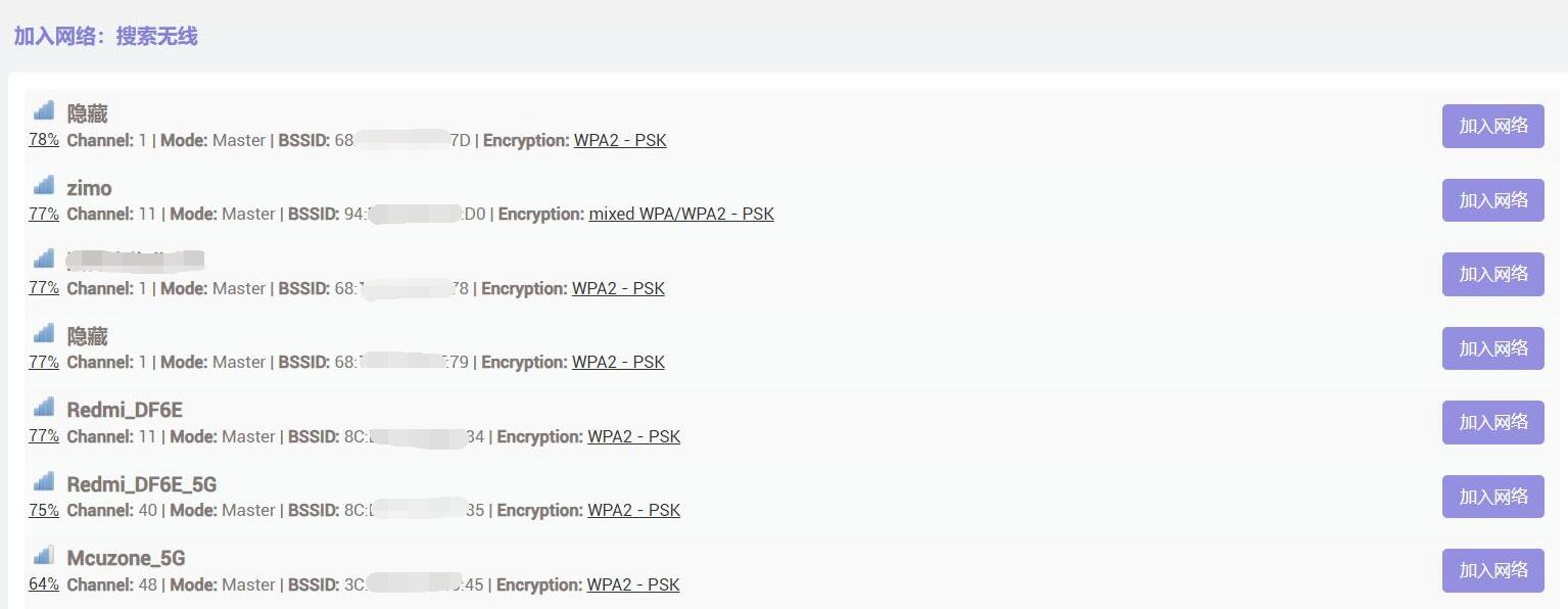
选择一个进行连接,防火墙选“WAN”:

然后按“提交”,提交后在点击“保存&应用”:
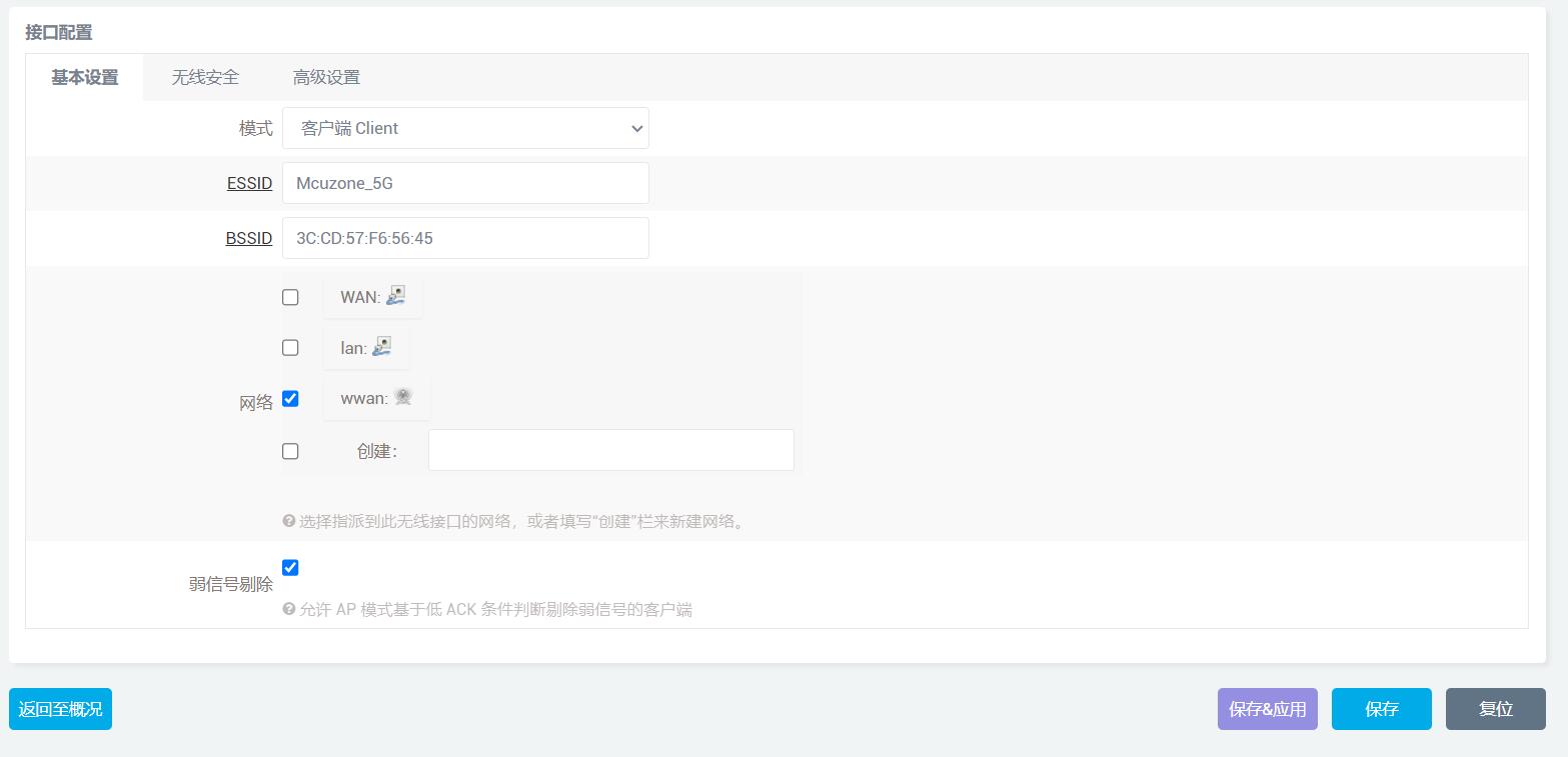
成功后再回到“无线概况”,就能看到此时无线已经连接成功:
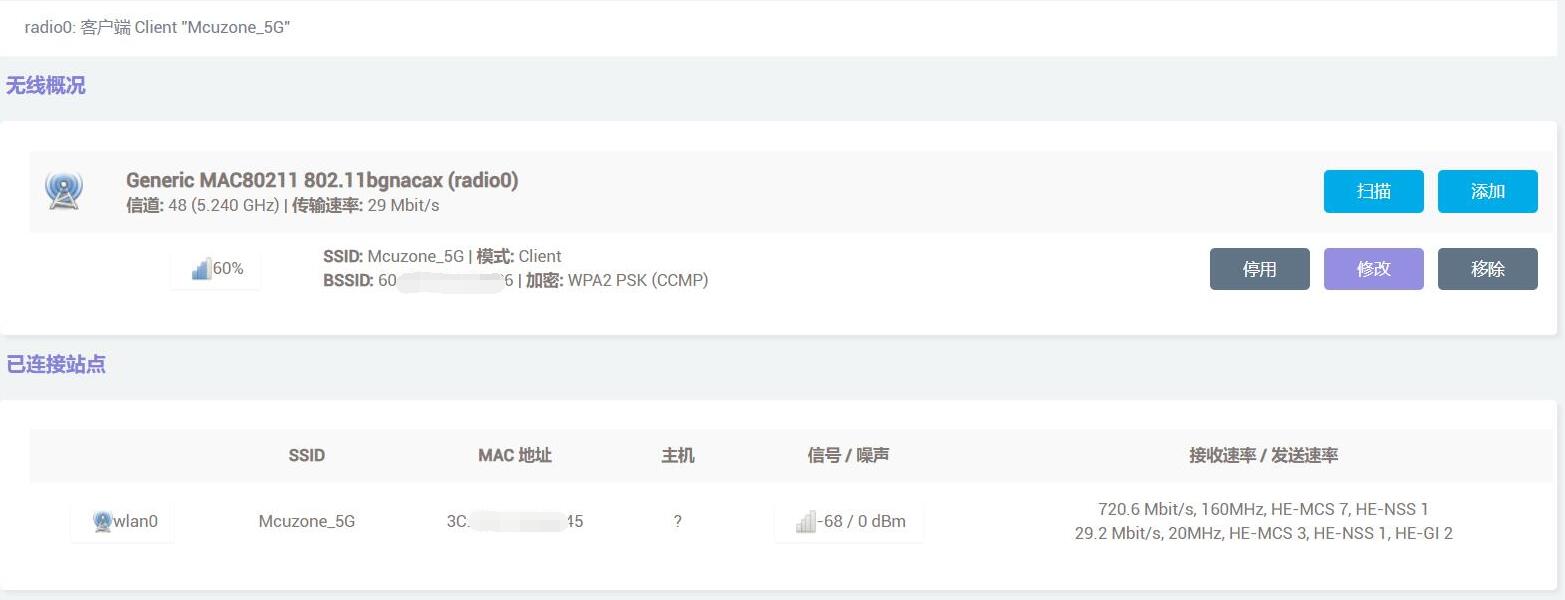
我们登录TTYD终端,运行ifconfig -a查看网络参数,可以看到无线网卡(wlan0)已经获取了IP地址:
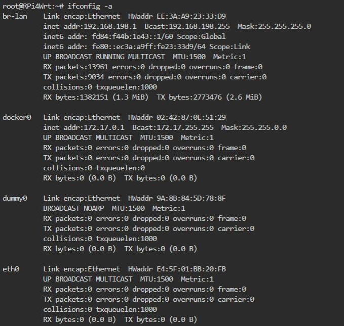
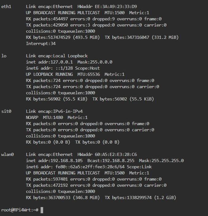
利用本扩展板做client,与电脑之间进行测速,结果如下:
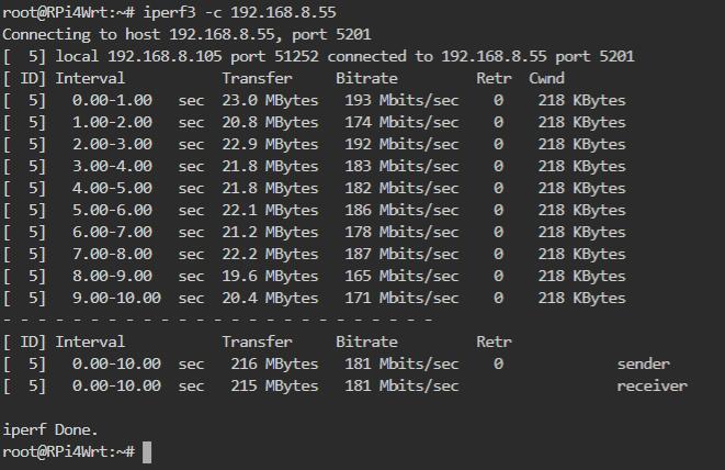
如果需要将扩展板做server,需要在”防火墙 - 常规设置 - 区域“中,将wan的入站数据等改成接受:

注意:网络测速受网络环境和测试方法影响,速度请以实际为准,本测试仅供参考。
5.5.2 WiFi6模块作为无线AP
AX210可以在2.4G模式下作为无线AP使用,AX200不能作为无线AP使用。本节使用AX210进行测试,实现千兆做WAN,AX210做LAN。
承接上一节,我们现在将千兆网口接上级路由器。然后在“网络 - 无线”里面点击“修改”:
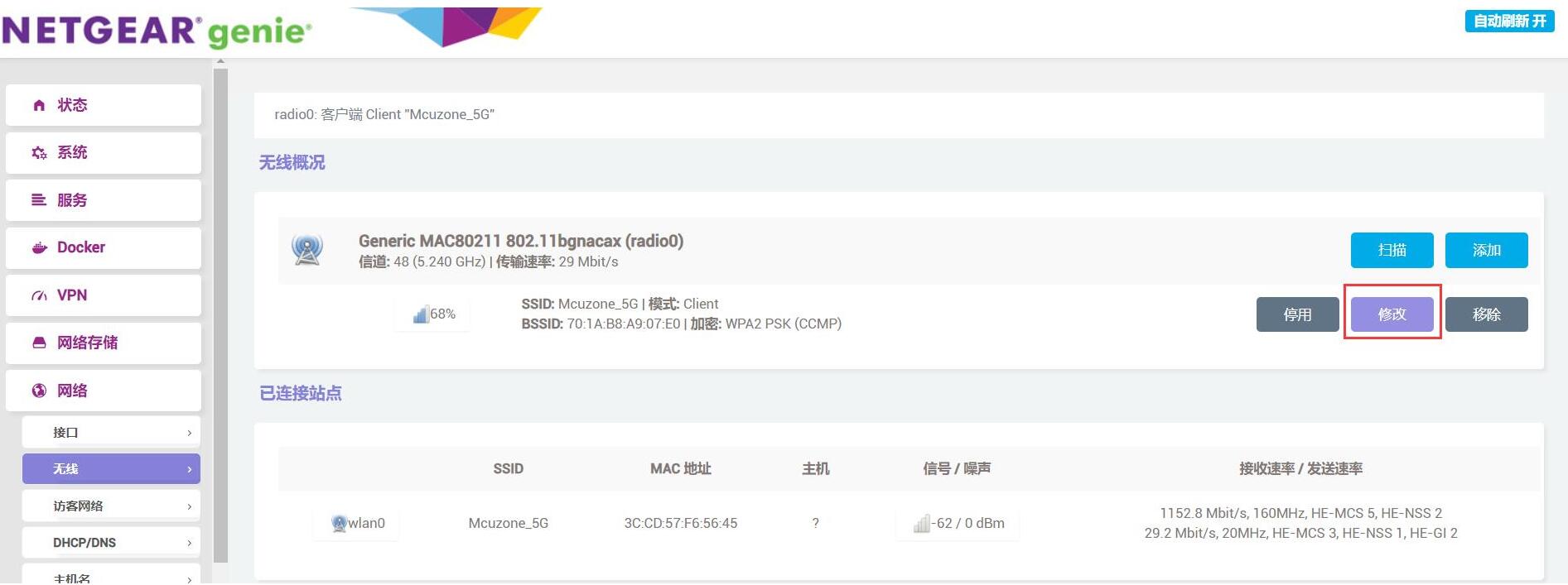
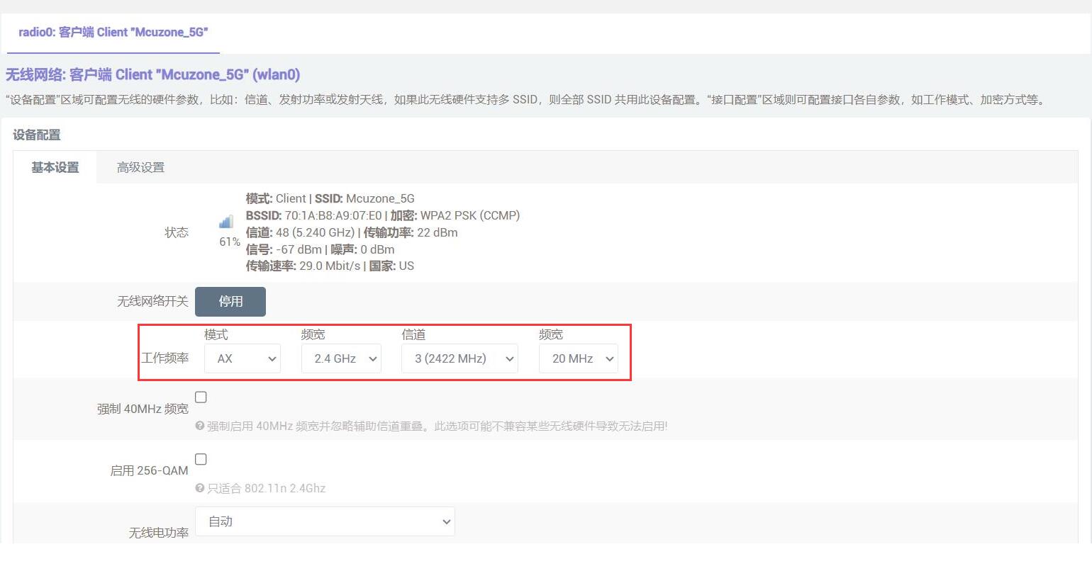
按照下图修改:
无线AP名称可以自己定义,我们这里取名“ AX210”: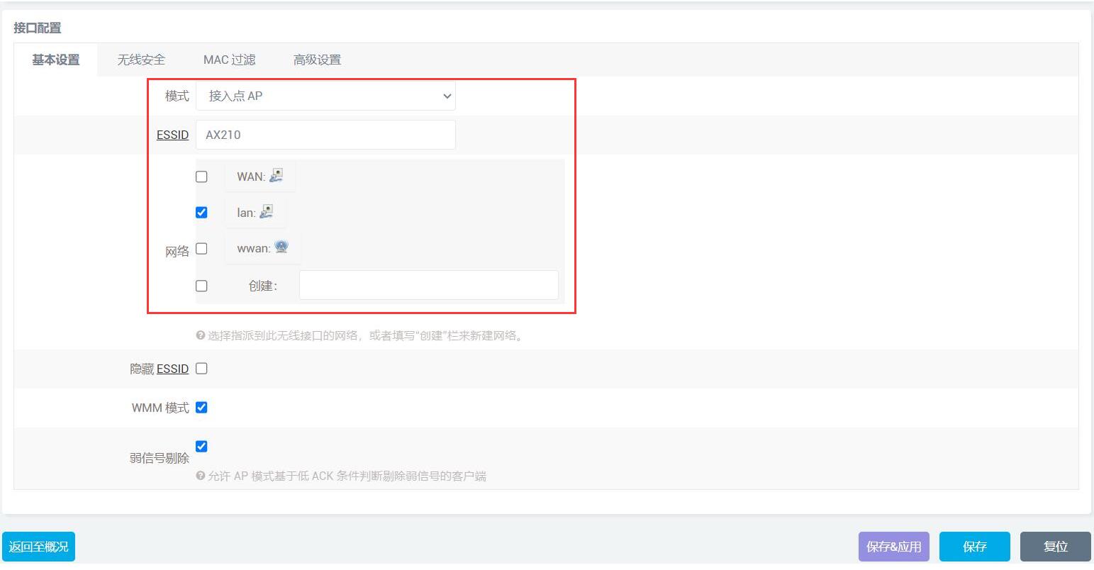
点击“保存&应用”,随后点击“网络 - 接口”,删除WWAN:
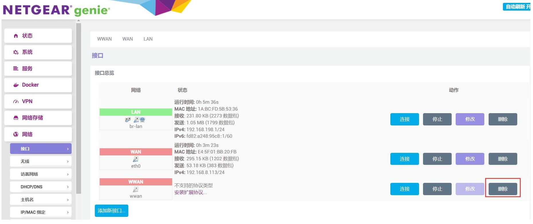
再点击LAN的“修改”:
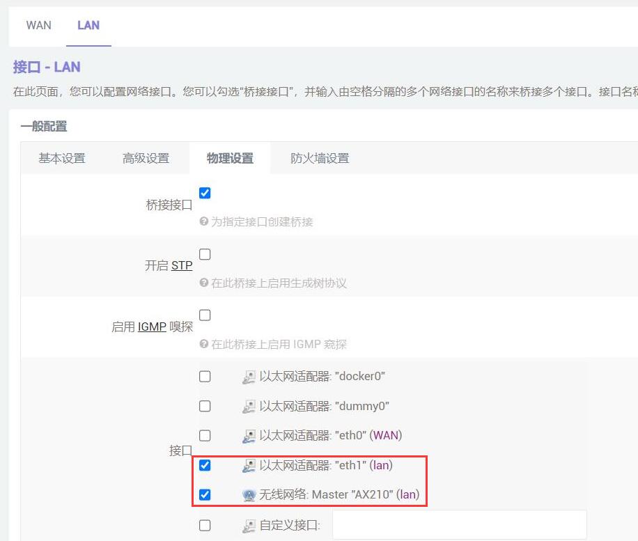
进入LAN的物理设置(将原先2.5G做LAN改成AX210做LAN),确认设置如下图:
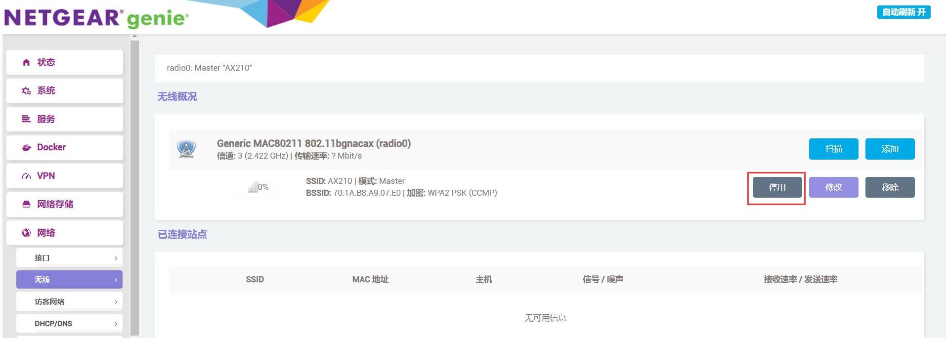
点击“保存&应用”,然后进入“网络 - 无线”,把这个AP先停用再启用:
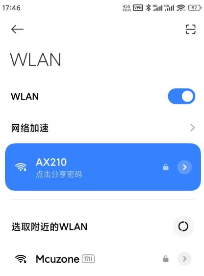
随后我们就能搜索到这个AP了,我们连接该AP,密码就是上一节连的无线AP的密码:
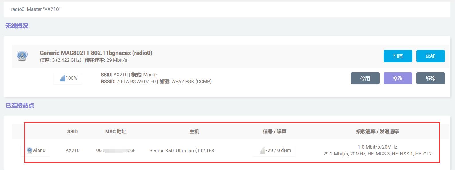
上网测速结果如下:

注意:网络测速受网络环境和测试方法影响,速度请以实际为准,本测试仅供参考。
5.6 5G模块测试
插上5G模块(本文档使用RM500U-CN为例)和sim卡,将与电脑连接的网线插到2.5G网口,原生千兆网口不插网线。
启动系统,点击“系统-TTYD终端”,登录后输入ifconfig -a查看网卡:
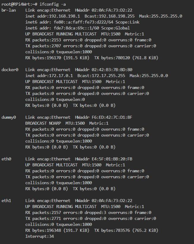
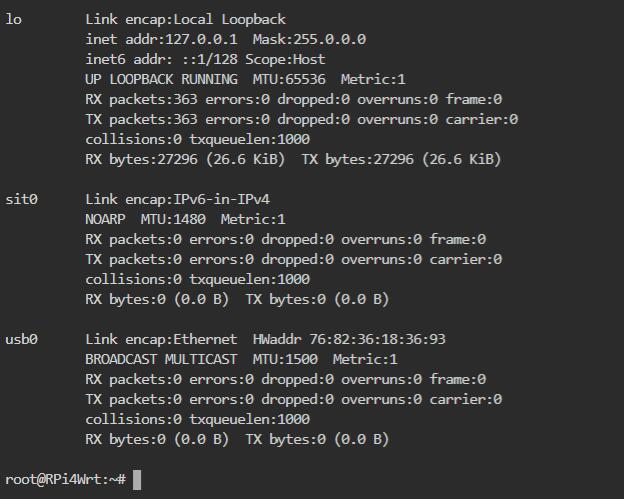
可以看到有一个名为usb0的网卡即为5G模组,但是无IP地址。
进入“网络 - 接口”,点击“添加新接口”:
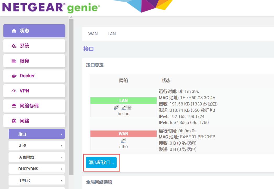
按下图配置,添加一个新接口,本文档为其命名为“5GWAN”:
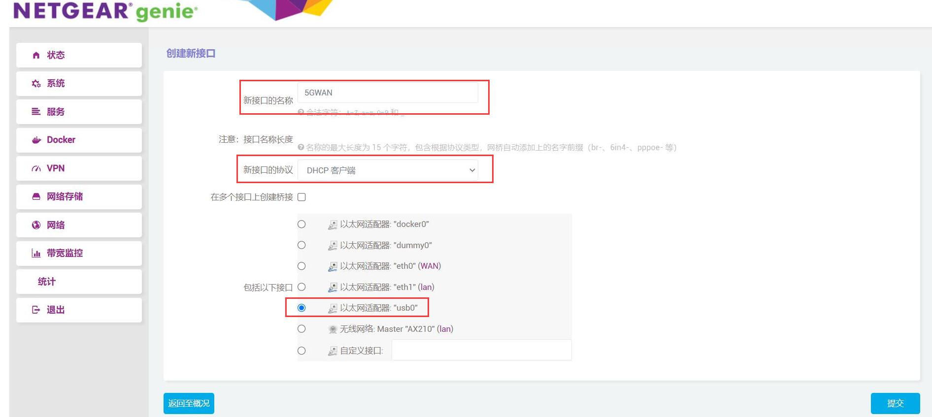
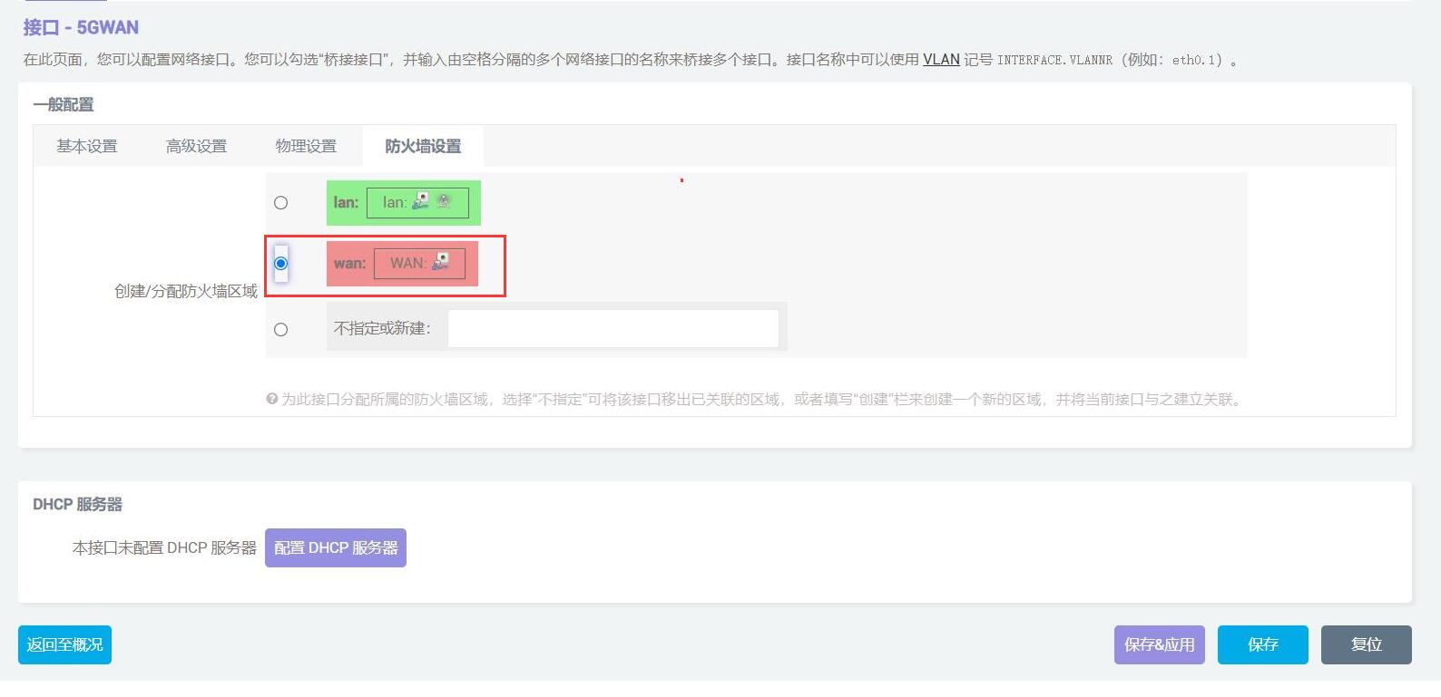
点击“提交”,然后进入“防火墙设置”,将防火墙区域设置为“WAN”:
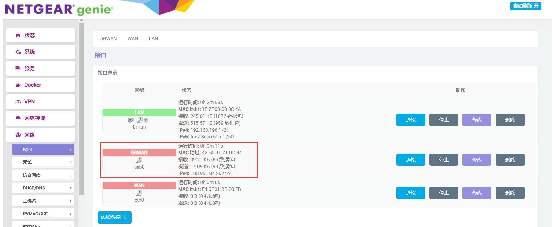
然后点击“保存&应用”,成功后返回“网络 - 接口”,此时我们就能看到5G模块已经获取到了IP地址,PC也能通过该5G模块上网:
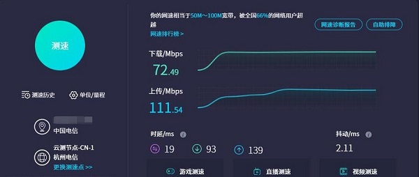
在PC上测试网速结果如下:
注意:网络测速受网络环境和测试方法影响,速度请以实际为准,本测试仅供参考。
六、功耗测试信息
| 系统待机功耗 | 使用时的功耗 | 模块之间相互使用 | 系统功耗 | |||
|---|---|---|---|---|---|---|
| 不接外设 | 0.756A | WiFi6从电脑写文件到SSD | 1.25A | |||
| 单独接5G | 0.9A | 1.9A(测速时) | WiFi6从SSD拖文件到电脑 | 1.72A | ||
| 单独接SSD | 0.847A | 2.5G从SSD拖文件到电脑 | 1.588A | |||
| 单独接WiFi6 | 0.83A | 1.15A | 2.5G从电脑写文件到SSD | 1.668A | ||
| 外设全接 | 1.15A | 5G从网页下载文件到SSD | 1.88A |
注意:上述数据为本公司的测试数据,仅供参考。
联系我们
电话:13957118045
如本页面有任何疏漏、错误或者侵权,请通过上述途径联系我们,谢谢!
Copyright 2004-2025 野芯科技


 QQ:8204136