0012 MPUUART/MP4232 EN
Keywords
Raspberry Pi 5, PCIe, Switch, VL805, TTL, RS232, RS485, Serial
I. Introduction
The Raspberry Pi 5 features a 16-pin PCIe interface, which can be utilized for the expansion of various peripherals.
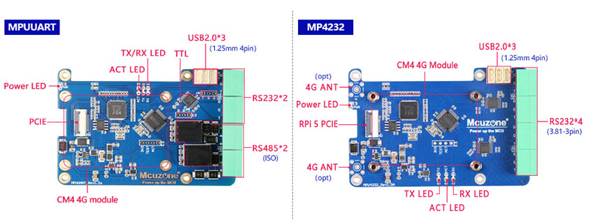
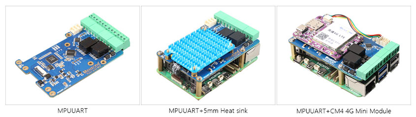
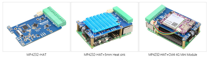
We can expand into four USB interfaces through the PCIe interface paired with a PCIe to USB chip, and then achieve four serial ports using the CH344Q chip. This expansion board comes in two versions: one is the MP4232 expansion board, which provides an expansion of 4 RS232 ports. This expansion board does not require any drivers under Raspberry Pi or Ubuntu and will be automatically recognized as four RS232 serial ports (ttyACM0, ttyACM1, ttyACM2, ttyACM3) once powered on. The other version is the MPUUART expansion board, which provides an expansion for dual RS232 and dual RS485 ports. This expansion board does not require any drivers under Raspberry Pi or Ubuntu and will be automatically recognized as ttyACM0, ttyACM1, ttyACM2, and ttyACM3 once powered on. Among these, ttyACM0 and ttyACM3 are RS232 serial ports, while ttyACM1 and ttyACM2 are RS485 serial ports.
The baud rate for RS232 can reach over 230 Kbps (with a tested speed of up to 1.2 Mbps when two adjacent RS232 ports are connected), while the baud rate for TTL/CMOS UART can reach up to 6 Mbps.
The expansion board also has three USB 2.0 ports reserved, which can be used to extend a 4G LTE module. The 4G module provided by our company is driver-free and dial-up-free on both the Raspberry Pi and Ubuntu. The system automatically recognizes it, allowing for plug-and-play functionality without the need to install additional drivers.
II. Hardware Spec
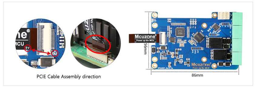
1. One PCIe interface, 0.5mm 16P FPC for communication with Raspberry Pi 5, adopting a design of PCIe to four high-speed USB2.0.
2. Three-way HS USB2.0, 1.25mm-4P interface, expandable CM4 4G Mini module.
3. The MPUUART expansion board converts four serial ports via a USB 2.0 high-speed interface, featuring two RS232 ports and two RS485 ports with power isolation design. The RS232 ports can be modified to a TTL/CMOS level UART and is led out through a 3.81-3Pin connector.
4. The MP4232 expansion board converts four serial ports via a USB 2.0 high-speed interface, implementing a four-channel RS232 design with 3.81-3p terminals.
5. Four LEDs are included: a PWR LED that is powered via the Raspberry Pi 5's PCIe interface, an ACT LED for the USB-to-serial chip, and two transmit/receive LEDs.
6. Size: 56x85mm, four M2.5 mounting holes, consistent with those on the Raspberry Pi 5;
7. The expansion board provides mounting holes for a 4G module and supports stacking of 1-3 4G modules.
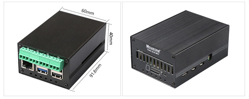
8. Aluminum alloy enclosure(OPT).
9. Customizable interface levels are available, such as configuring four TTL/CMOS serial ports, or four RS485 serial ports.
10. The MPUUART uses gold immersion process, lead-free production, and the material has passed UL and ROHS certifications with a flame retardant rating of 94V-0.
III. Work with Raspberry Pi OS
Since the expansion board utilizes the PCIe interface of the Raspberry Pi 5, the system can only be booted from an SD card (TF card).
Please refer to the following link for instructions on how to burn the system image to a TF card:
The version of the Raspberry Pi OS is: 2024-07-04-raspios-bookworm-arm64.img.xz
You can download the Raspberry Pi OS in:
https://www.raspberrypi.com/software/operating-systems/#raspberry-pi-os-64-bit
3.1 Install CuteCom
The installation command for CuteCom is:
sudo apt install cutecom
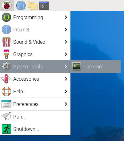
After installation, click on the Raspberry Pi icon in the top left corner of the desktop, and you will find a shortcut for CuteCom under "System Tools".
3.2 Test MP4232
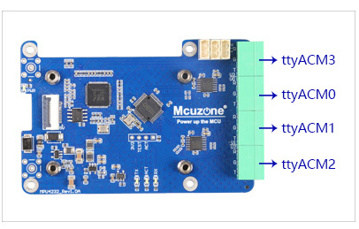
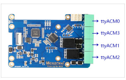
The names of the four serial ports on the MP4232, from top to bottom, are as follows:
ttyACM3、ttyACM0、ttyACM1、ttyACM2
The connection correspondence between the two RS232 serial ports is:
R - T
G - G
T - R
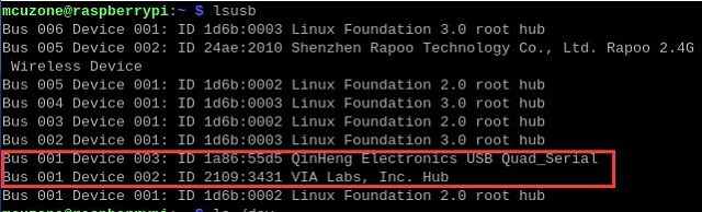
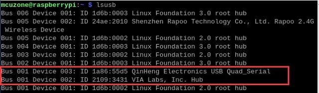
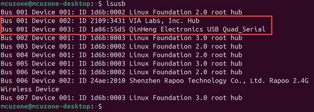
Execute lsusb, and we can see VL805 and CH344Q:
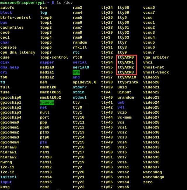
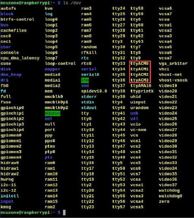
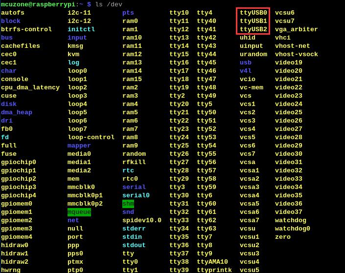
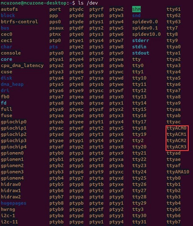
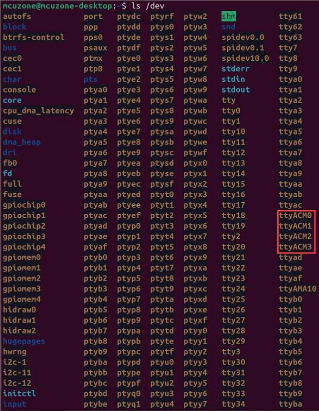
Execute ls /dev, and we can see four serial ports: ttyACM0、ttyACM1、ttyACM2、ttyACM3:
We use a serial cable to connect any two of the serial ports and perform data transmission tests using CuteCom. According to the tests, under the Raspberry Pi system, the baud rate can reach up to 1.21 Mbps (based on data transmission without garbling).

3.3 Test MPUUART
The MPUUART has four serial ports; the two on top are RS232 ports (ttyACM0, ttyACM3), and the two at the bottom are RS485 ports (ttyACM1, ttyACM2).
The connection correspondence between the two RS485 serial ports is:
G - G
A - A
B - B
Execute lsusb, and we can see VL805 and CH344Q:
Execute ls /dev, and we can see four serial ports: ttyACM0、ttyACM1、ttyACM2、ttyACM3:
We use a serial cable to connect two of the RS232 serial ports and perform data transmission tests using CuteCom. According to the tests, under the Raspberry Pi system, the baud rate can reach up to 1.22 Mbps (based on data transmission without garbling).

We use a serial cable to connect two of the RS485 serial ports and perform data transmission tests using CuteCom. According to the tests, under the Raspberry Pi system, the baud rate can reach up to 2.02 Mbps (based on data transmission without garbling).

3.4 Test 4G module
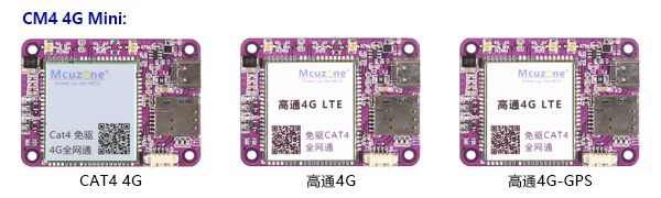
The CM4 4G mini module provided by our company is driver-free, does not require dialing, and is automatically recognized with plug-and-play functionality under the Raspberry Pi system. The 4G models include CM4 4G mini (CAT4 4G), Qualcomm 4G, and Qualcomm 4G-GPS.
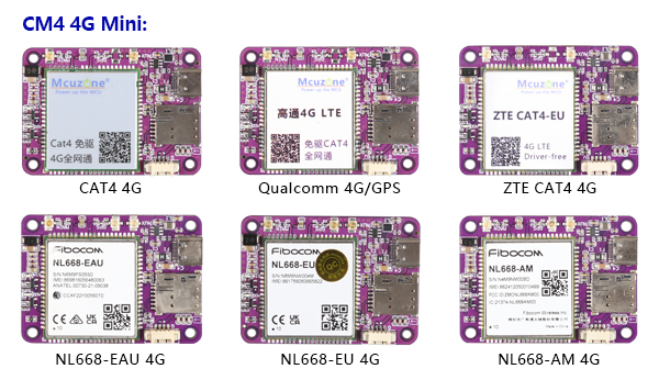
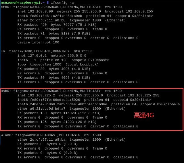
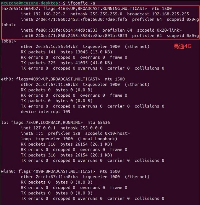
The CAT4 4G is recognized as an eth device in the system, while the Qualcomm 4G is recognized as a usb0 device in the system.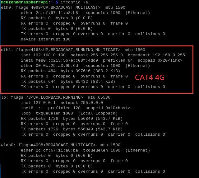
3.4.1 Module connection
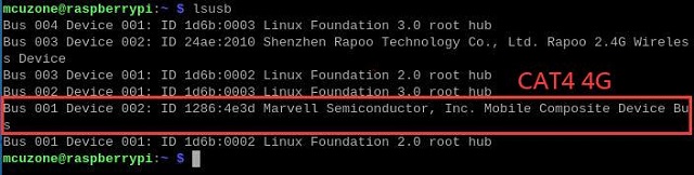
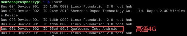
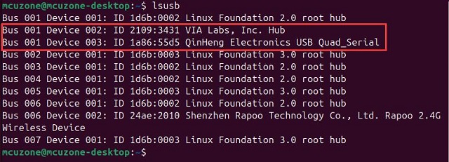
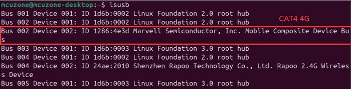
After starting Raspberry Pi OS, execute lsusb, as shown in the following image:
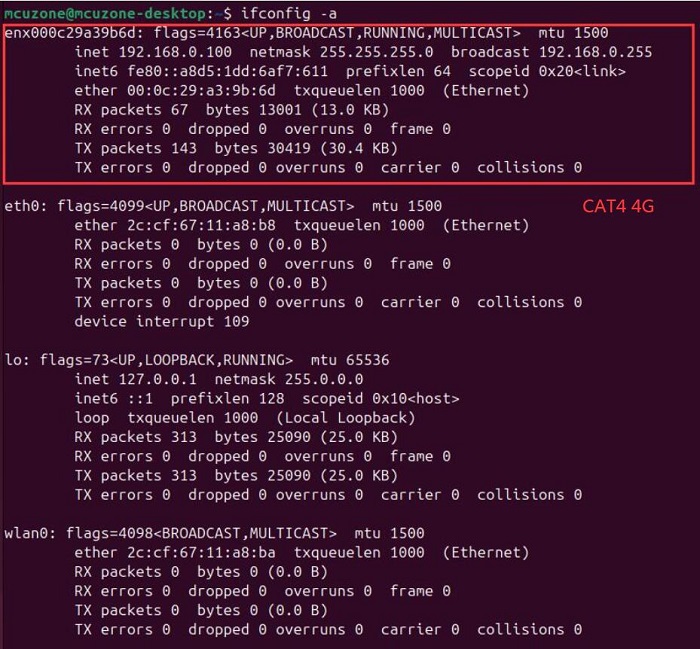
Execute ifconfig -a, and we can see that the 4G module (eth1 or usb0) has correctly obtained an IP address.
If you cannot see the 4G module (eth1), please check if the connections are correct and use the lsusb command to verify if the module is recognized by the OS.
The status of Statu LED:
CAT4 4G:
The blinking pattern, where the light is on for 1.8 seconds and off for 0.2 seconds (alternatively, you can judge by the light being on longer than it is off), indicates that the 4G module has connected to the network.
The blinking pattern, where the light is off for 1.8 seconds and on for 0.2 seconds, indicates that there is an issue with the SIM card or the network. Please check the SIM card and the antenna.
Qualcomm 4G:
If the LED is blinking slowly with occasional rapid flashes in between, it indicates that the 4G module has connected to the network. Otherwise, it suggests there might be an issue with the SIM card or the network; please check the SIM card and the antenna.
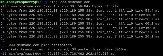
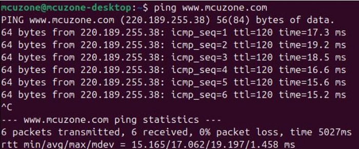
After the 4G module correctly obtains an IP address, we can ping an external web address, such as:
ping www.mcuzone.com
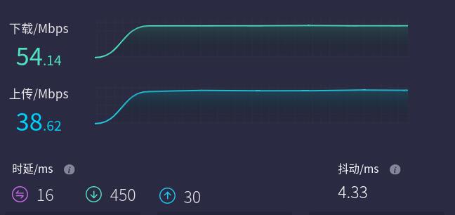
You can also connect to the external network through the 4G module and visit a speed test website to measure the speed:
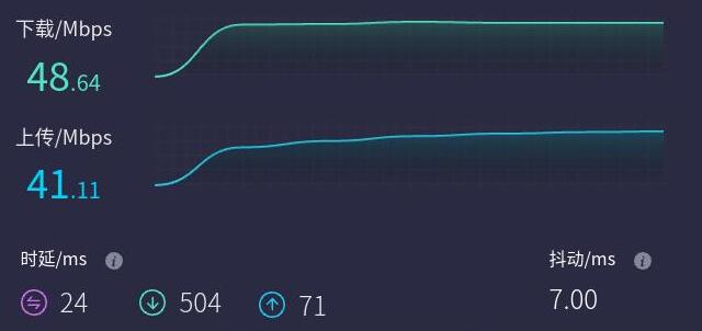
Note: Network speed tests are affected by the network environment and testing methods. Please refer to the actual speed, as this test is for reference only.
3.4.2 AT command operation
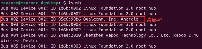
Taking CAT4 4G as an example, execute lsusb in termina::
Record the ID value of the 4G module: 05c6 90b6
Use the following command to open the ttyUSB serial port, where the value after echo is the ID recorded above:
sudo modprobe option
sudo sh -c 'echo 05c6 90b6 > /sys/bus/usb-serial/drivers/option1/new_id'
After execution is complete, the system should have four additional devices: ttyUSB0 - ttyUSB3, execute ls /dev/ttyUSB* to view:

Install minicom:
sudo apt-get install minicom
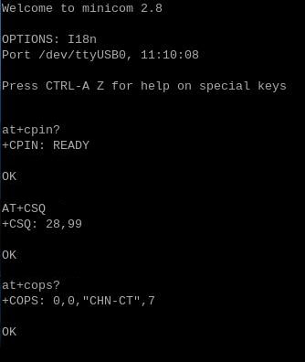
Open AT Command serial port by minicom:
sudo minicom -D /dev/ttyUSB1
(Note: Which serial port to use should be determined by the ability to enter and execute AT commands without garbled or erratic output after accessing that serial port.)
If you need to view the echo, please type the command ate1, then execute other commands.
Common AT command:
1) Check if the SIM card is detected:
at+cpin?
Return ready to indicate the card has been recognized, if return error, you need to check the hardware.
2) Check antenna signal quality:
at+csq
eturn values between 26 and 31 indicate a good signal, with 31 representing a full signal strength; return values between 20 and 25 indicate a barely acceptable signal; return values below 20 indicate a poor signal or that the antenna might not be connected.
3) Check network registration status:
at+cops?
Normally, it should return the network supporter's code: 7, where 7 represents 4G.
Note: The above command at+csq should not include a question mark, while the other two commands require a question mark.
4) View the SIM card's IMEI code:
at+cgsn
5) Reset 4G module (Sometimes, if you reinsert the SIM card, hot swapping may not work; in such cases, you can use this reset command to reset the module.):
at+reset
6) Disable radio frequency:
at+cfun=0
Enable radio frequency:
at+cfun=1
The two commands mentioned above can be used in pairs to allow the module to re-register with the network without restarting the 4G module.
3.4.3 Modify the IP address of the 4G module
如果出厂默认的4G IP地址和用户使用的IP地址有冲突,或有修改IP地址的需求,可按照下列步骤进行修改:
If the default 4G IP address assigned at the factory conflicts with the IP address being used by the user, or if there is a need to modify the IP address, you can change the 4G module's IP to directly obtain a public IP.
CAT4 4G:
Execute the AT command:
AT+ROUTEIP=<newip>
Note: only addresses in the format of 192.168.x.1 are supported. If you set AT+ROUTEIP=192.168.3.1, the final IP address obtained will be 192.168.3.100. After making the changes, you need to power off and restart the OS.
Query current IP: AT+ROUTEIP?, it returns two values, the first one is the old IP, and the second one is the new IP.
Test command: AT+ROUTEIP=?
Qualcomm 4G:
Set the 4G module's IP to directly obtain a public IP. Please execute the AT command:
Set the IP to public: AT+GTIPPASS=1
Set the IP to private: AT+GTIPPASS=0
Check whether the current IP is a public or private IP: AT+GTIPPASS?
After modifying the IP, a power cycle reboot is required for the changes to take effect.
3.4.4 GPS test (Applicable to the Qualcomm 4G-GPS)
If you have chosen the Qualcomm 4G-GPS, this 4G module comes with GPS functionality. You need to connect a passive GPS antenna and ensure that the GPS antenna is placed outdoors.
Execute the command lsusb, as shown in the figure below:
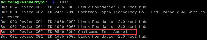
Note down the ID of the 4G module: 05c6 90b6.
Use the following command to open the ttyUSB serial port, where the value following echo is the ID value recorded above:
sudo modprobe option
sudo sh -c 'echo 05c6 90b6 > /sys/bus/usb-serial/drivers/option1/new_id'
After executing the two commands above, the system should have three additional devices: ttyUSB0/1/2. You can check them by executing ls /dev:
Execute minicom and open the ttyUSB0 serial port:
sudo minicom -D /dev/ttyUSB0
Then execute:
at+gtgpsepo=1 //Enable AGPS
at+gtgpspower=1 //Enable GPS
Wait a moment for the positioning to succeed, then execute:
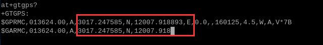
at+gtgps? //View NMEA information
You can then see that the serial port outputs GPS information:
四、Ubuntu系统的使用
我们测试用的Ubuntu系统版本为ubuntu-24.04-preinstalled-desktop-arm64+raspi.img.xz,
Ubuntu OS下载地址:
https://ubuntu.com/download/raspberry-pi
4.1 安装串口软件CuteCom
串口软件CuteCom的安装命令为:
sudo apt install cutecom
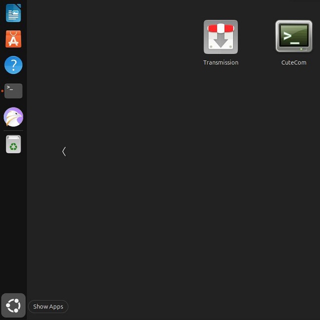
安装完毕后,点击桌面左下角的“Show Apps”图标,有CuteCom的快捷方式:
但是如果在此直接打开CuteCom,有可能会出现Input框无法输入字符的问题,这是由于权限不足造成的,所以需要打开Ubuntu终端,输入:
sudo cutecom
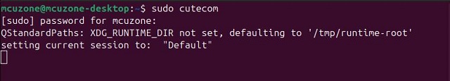
来打开CuteCom,如果需要打开第二个CuteCom,则需要再开一个Ubuntu终端,输入打开CuteCom的命令。
4.2 测试MP4232
MP4232扩展板的4个232串口名称从上到下依次如下:
ttyACM3、ttyACM0、ttyACM1、ttyACM2
两个RS232串口之间的连接对应关系为:
R - T
G - G
T - R
在Ubuntu终端中输入lsusb,我们可以看到VL805和CH344Q:
输入ls /dev,我们可以看到4个串口ttyACM0、ttyACM1、ttyACM2、ttyACM3:
我们用串口连接线连接任意两个串口,使用CuteCom进行数据收发测试,经测试,Ubuntu系统下波特率最高可达到1.15M(以传输数据不发生乱码为准):

4.3 测试MPUUART
MPUUART扩展板的4个串口,靠上的两个为RS232串口(ttyACM0、ttyACM3),靠下的两个为RS485串口(ttyACM1、ttyACM2)。
两个RS485串口之间的连接对应关系为:
G - G
A - A
B - B
在Ubuntu终端中输入lsusb,我们可以看到VL805和CH344Q:
输入ls /dev,我们可以看到4个串口ttyACM0、ttyACM1、ttyACM2、ttyACM3:
我们用串口连接线连接两个RS232串口,使用CuteCom进行数据收发测试,经测试,树莓派系统下波特率最高可达到1.26M(以传输数据不发生乱码为准):

我们用串口连接线连接两个RS485串口,使用CuteCom进行数据收发测试,经测试,树莓派系统下波特率最高可达到1.98M(以传输数据不发生乱码为准):

4.4 测试4G模块
我司配套的CM4 4Gmini模块,在Ubuntu系统下均为免驱免拨号,自动识别,即插即用,插手机SIM卡(4G以上),接天线。4G型号分CM4 4G mini(CAT4 4G),高通4G,高通4G-GPS。
4G模块在Ubuntu系统里识别成以enx开头的设备。4G的其他操作,比如使用AT命令,修改IP地址或者GPS的使用等,均和树莓派系统一样。此处不再重复。
系统上电启动运行Ubuntu系统后,在树莓派终端中执行命令lsusb,如下图所示:
在Ubuntu终端中执行ifconfig -a,我们可以看到4G模块(enx开头的网卡)已经正确获得了IP地址:
Statu LED灯状态如下:
CAT4 4G:
闪烁状态为1.8秒亮0.2秒灭(也可以通过亮的时间比灭的时间长来判断)表示4G模组已经联网。
闪烁状态是1.8秒灭0.2秒亮,说明SIM卡或者网络有问题,请检查SIM卡和天线。
高通4G:
闪烁状态为慢闪,中间有短暂快闪,表示4G模组已经联网;否则说明SIM卡或者网络有问题,请检查SIM卡和天线。
4G模组正确获得ip地址后,我们可以ping外网地址,如:
ping www.mcuzone.com
也可以通过4G模块连接外网,访问测速网站测速,结果如下:
注意:网络测速受网络环境和测试方法影响,速度请以实际为准,本测试仅供参考。== 联系我们 ==


 QQ:8204136
电话:13957118045
如本页面有任何疏漏、错误或者侵权,请通过上述途径联系我们,谢谢!
Copyright 2004-2025 野芯科技