2003 CM4 Tiny HDMIx2(Dual HDMI Expansion Board)
Keywords
Raspberry Pi, CM4 Core board, System Flashing, 4G, RPiOS, eMMC, Dual HDMI, Dual-screen different display
I. Introduction
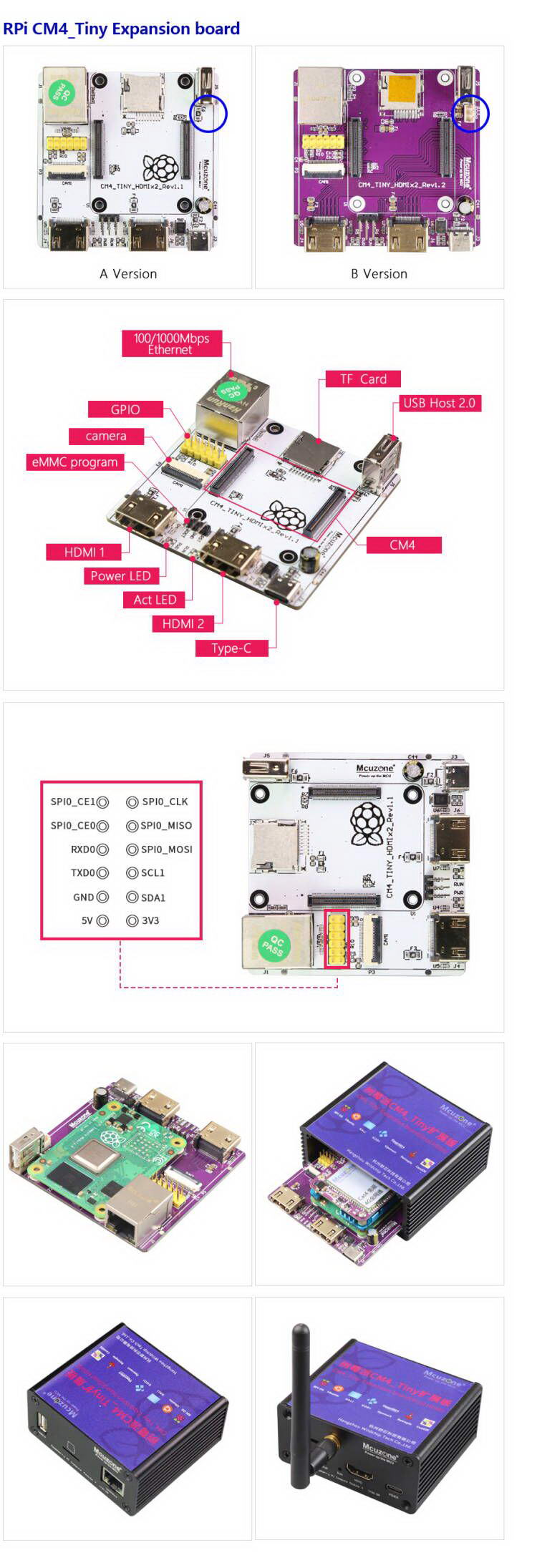
The CM4_Tiny dual HDMI expansion board is designed based on the Raspberry Pi CM4 core board and is a expansion board for applications such as media players, dual-screen different displays, image and video capture, human-computer interaction, remote control, and more.
The CM4_Tiny dual HDMI expansion board has two full-sized HDMI ports, which can be used to output different content to two display devices, and it supports 4K output. It also has native Gigabit Ethernet and a native USB host port, and it includes a reserved 22-pin 0.5mm CAM interface, which can be used to connect various cameras for image and video capture and processing. In addition, there is a 2.54mm pitch 2x6 GPIO header, it is containing I2C, UART, and SPI signals, which can be used for conventional peripheral expansion.
The CM4_Tiny dual HDMI expansion board is powered by a USB-C port at 5V3A.
II. Hardware Resources
1. One native Gigabit Ethernet port, using an integrated transformer, which provides better electromagnetic performance.
2. Two standard HDMI ports, supporting 4K output.
3. One native USB OTG A port (an USB A-A cable can be optionally used to flash system for the eMMC version of the core board via this host port).
4. One camera CSI interface, 22-pin with 0.5mm pitch, with an optional flexible flat cable adapter from 1mm 15-pin to 0.5mm 22-pin.
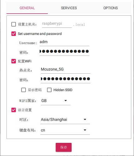
5. The 12-pin GPIO is broken out, containing I2C, UART, and SPI signals, 2.54mm.
6. One USB-C power supply interface, 5V3A, supporting PD protocol chargers.
III. System flashing and setting
3.1 Overview
This document uses the Raspberry Pi OS and OpenWrt system for testing.
The version of the Raspberry Pi OS is: 2024-07-04-raspios-bookworm-arm64.img.xz
You can download the Raspberry Pi OS in:
https://www.raspberrypi.com/software/operating-systems/#raspberry-pi-os-64-bit
The version of the OpenWrt is: openwrt-bcm27xx-bcm2711-rpi-4-squashfs-sysupgrade-linux-6.1.100-20240805.img.gz
3.2 Boot from TF card
If the core board does not have an eMMC, the system will boot from the TF card.
3.2.1 Use the Imager to flash the system
First, install the Imager on the Windows. You can download it in: https://www.raspberrypi.com/software/
Insert the TF card into the card reader after installation, plug the card reader into the PC's USB port, and then open the software.
Raspberry Pi Device: Choose Raspberry Pi 4;
Operating System:
Choose Raspberry Pi OS(64-bit), to flash the system image downloaded from the Raspberry Pi official website (internet connection required).
Choose Use Custom, to flash the system image already downloaded onto the hard drive (no internet connection required).
Storge: Select the TF card that needs to be flashed (i.e., the card inserted into the PC's USB port).

After making your selection, press "NEXT." It is recommended to click "Edit Settings" to pre-set some parameters in the flashing software. This way, you won't need to set them again when the system starts up, making it easier to use.

If you need to use the pre-set settings, press "Yes"; if you do not need to use the pre-set settings, press "No". Proceed to the next page, and click "Yes" to start the flashing and verification process. After the flashing is complete, follow the prompts to remove the card.

The above instructions describe how to flash the Raspberry Pi OS. For flashing the Ubuntu system or the OpenWrt system, similar operations are used; when you reach the step "Operating System", you need to select Use Custom, and then choose the pre-downloaded image.
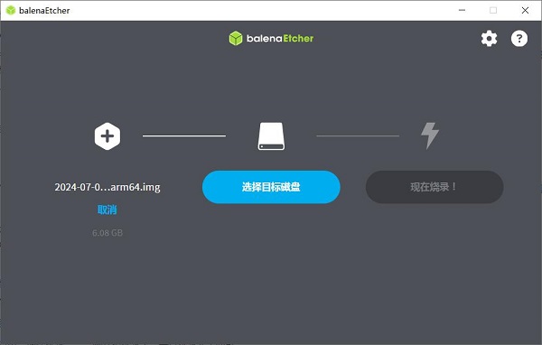
3.2.2 Use the balenaEtcher to flash the system
First, install the balenaEtcher on the Windows. You can download it in: https://etcher.balena.io/#download-etcher
Insert the TF card into the card reader after installation, plug the card reader into the PC's USB port, and then open the software.
Flash from file: Select the pre-downloaded Raspberry Pi OS or Ubuntu system image.
Select target: Select the TF card that needs to be flashed (i.e., the card inserted into the PC's USB port).
Then click "Flash!" to start the process, and wait for it to complete.
3.2.3 Boot the system
Remove the TF card from the card reader, insert it into the TF card slot of the Raspberry Pi, and power the board on to enter the system.
3.3. Boot from eMMC
If the core board has onboard eMMC, the system will ignore the TF card and boot from the eMMC instead.
To flash the system to the eMMC, you need to install the driver package on the PC first. You can download it in:
http://www.mcuzone.com/down/Software.asp?ID=10000623
Then use a jumper cap to short the BOOT pin and the GND pin on the expansion board (located between the two HDMI ports):
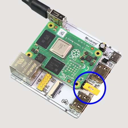
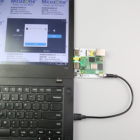
Use a USB Type A-A data cable to connect the USB OTG port (i.e., the USB-A port on the expansion board) to the computer.
After connecting to the computer, open the Computer's Device Manager and check if a new USB device appears. In the image below, it is a USB device named "BCM2711 Boot":

Under All Programs in the PC's Start menu, there is a shortcut called rpiboot under Raspberry Pi.

Open this software, and the computer will format and partition the eMMC or TF card:

Wait a moment; a partition will appear in the File Explorer (in this example, the partition is named bootfs, but the actual name may vary):

Then, we can use the balenaEtcher software to flash this partition.
Open the balenaEtcher software, first, click "Flash from file" and select the file you want to flash to the eMMC. then, choose the bootfs partition mentioned above, and click "Flash!" to start flashing the file:


After the flashing is complete, we need to remove the jumper cap that was previously connected; otherwise, the core board will not start normally. Then, power the system on, and wait for it to boot up.
IV. Hardware testing under Raspberry Pi OS
4.1 Native Gigabit Ethernet port test
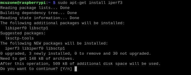
Plug the Ethernet cable into the native Gigabit Ethernet port. The system will automatically acquire an IP address. Open the terminal and install the speed testing software iperf3.
sudo apt-get install iperf3
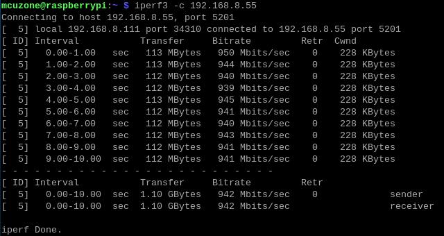
Then we use iperf3 for testing.
The speed test results for the native Gigabit Ethernet, with the client mode showing about 942Mbps:
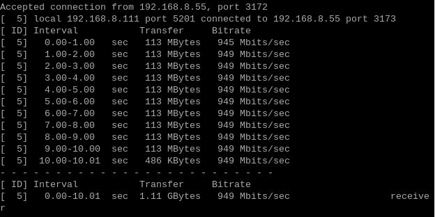
The server mode showing about 949Mbps:
Note: The speed of the native Gigabit network test can be affected by the network environment and the testing method. Speeds should be considered based on actual results; this test is for reference only.
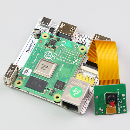
4.2 CSI test
First, connect the camera to the CAM1 interface (this document uses the OV5647 camera):
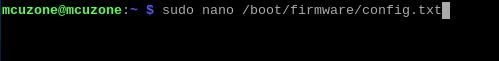
After connecting everything, power on the board. Once the system is running, open the terminal and run the following command:
sudo nano /boot/firmware/config.txt
Add the following statements at the end of the file:
dtoverlay=ov5647,cam1
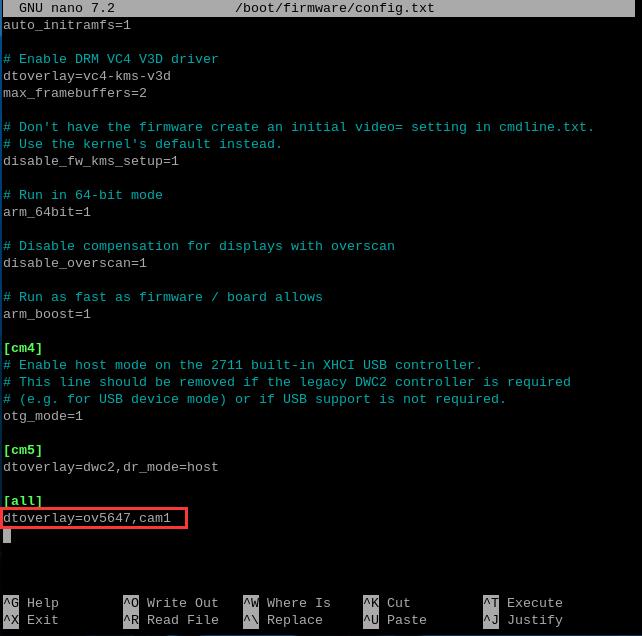
In actual use, add according to your model, save the changes, and then restart the system to be able to use the OV5647 camera.
After rebooting, enter the following command in the terminal:
ls /dev
Then you will be able to see the video0 device.
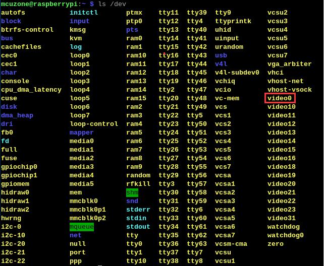
Note: The expansion board leads out CSI1 (which is labeled as CAM1 on the silkscreen). Thus, only one CSI interface is initialized, so only one CSI device is displayed. Therefore, in the /dev directory, what is shown is the first CSI device, video0.
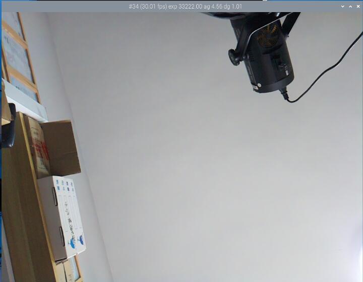
Enter libcamera-hello --camera 0 in the terminal to open the corresponding camera for viewing.

If you need to take a photo, enter:
libcamera-jpeg -o test.jpg

The photo is saved in the /home/mcuzone directory (which is the home directory), and the photo effect is as follows:
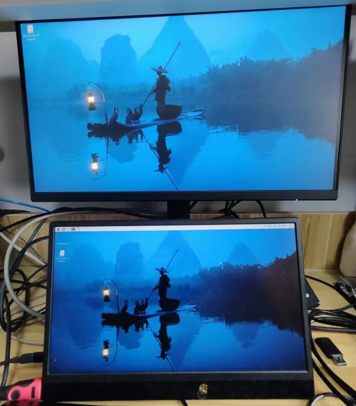
4.3 Dual HDMI test
Plug a separate monitor into each HDMI port on the expansion board to achieve dual-screen extended display, with the monitor pluged first serving as the primary screen.

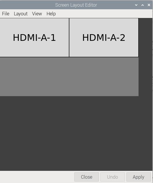
Click on the Raspberry Pi logo in the top left corner; under Preferences, there is a shortcut called Screen Configuration.
After opening the software, you can adjust parameters such as the relative position, resolution, orientation, and refresh rate of the dual screens:
4.4 Expansion 4G module test
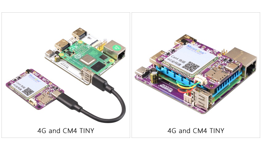
This expansion board has 2 versions, and the methods for connecting the 4G module are as follows:
1. If you have version A of the expansion board, use a USB Type C-A cable to connect the 4G module to the USB Type A port on the expansion board.
2. If you have version B of the expansion board, connect the 4G module and the expansion board, by the 4G module's 1.25 4-pin connector to the built-in 1.25 4-pin USB port on the expansion board, and it can also fit into the enclosure.
Whichever method is used, it will occupy the USB Type A port on the expansion board, so you will not be able to use a keyboard or mouse at this time. You will need to use SSH software to access the operating system via the Ethernet port.
If there is a need to use a keyboard and mouse, you can connect a USB HUB to version A of the expansion board, and then plug the 4G module and the keyboard/mouse into the USB HUB. However, due to the higher power consumption of the 4G module, it is recommended to use a USB HUB with external power.
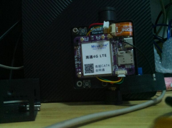
The 4G module model used in this document is the CM4 4G mini (domestic CAT4).
After correctly connecting the expansion board and the 4G module, boot the system and execute the command lsusb in the SSH software, as shown in the following figure:

This module's id is 1286 4e3d.
- By running
ifconfig -ain the SSH software, we can see that the 4G module (eth1) has correctly obtained an IP address:
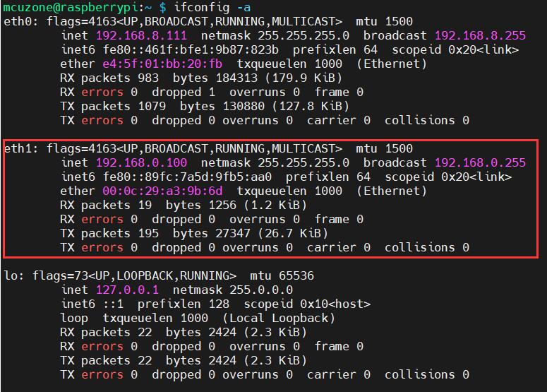
After the 4G module correctly obtains an IP address, we can ping external network addresses, such as:
ping www.mcuzone.com
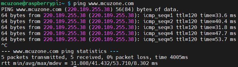
This indicates that internet access is now normal.
V. Hardware testing under OpenWrt system
This expansion board, when paired with the Raspberry Pi CM4 core board, can be configured as a one-in-one-out switch mode under the OpenWrt system:
Method 1: The 4G module on the expansion board can serve as the WAN port (direct 4G internet access), while the Ethernet port is configured as a LAN port, used for connecting to a PC (4G input, wired Ethernet output).
Method 2: Configure the WiFi of the CM4 core board as the WAN port (the CM4 core board must have the WiFi module), and set the network port of the expansion board as the LAN port (WiFi in, Ethernet out).
The version of the OpenWrt is: openwrt-bcm27xx-bcm2712-rpi-5-squashfs-sysupgrade-linux-6.1.100-20240805.img.gz
5.1 Preparations
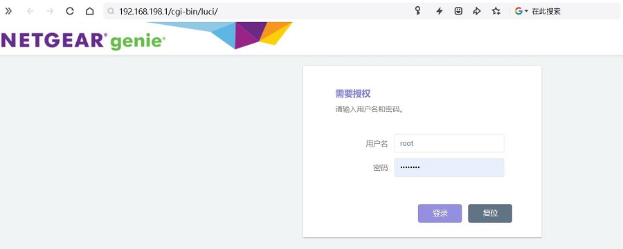
After flashing the OpenWrt system and powering the board on, we connect the Ethernet cable from the expansion board's built-in Ethernet port to the PC's Ethernet port. After the PC's network card successfully connects to the expansion board's Ethernet port, we can find Network & Internet settings in the Windows settings. In the Ethernet open the "Change adapter options - Ethernet - Status" and view the IP address of the default gateway; this address is the backend configuration page address for the OpenWrt system. As shown in the figure, the address tested in this document is 192.168.198.1:
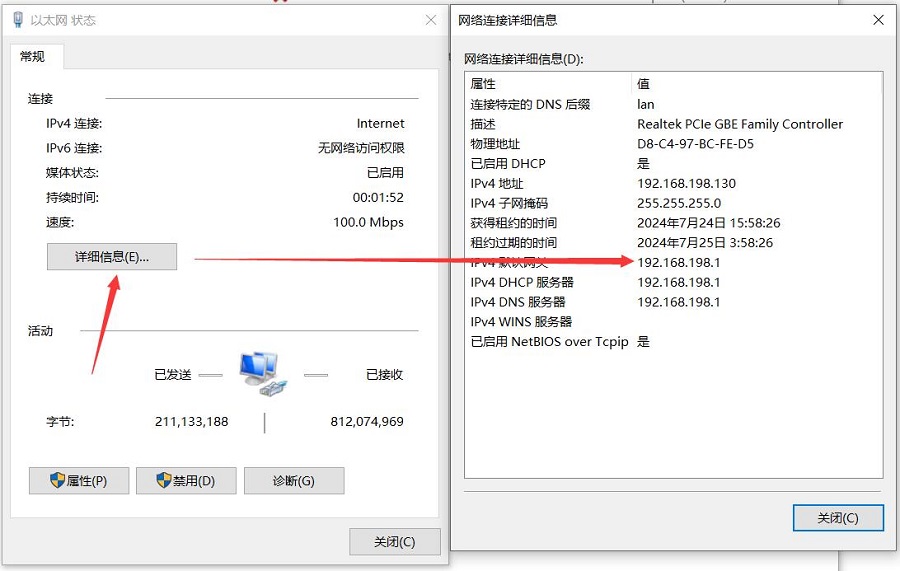
Then open a web browser and enter 192.168.198.1 to access the OpenWrt system. The default username is root, and the default password is password.
5.2 Native Gigabit Ethernet port test
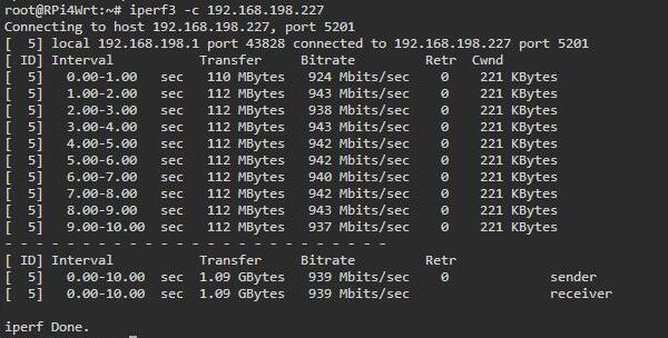
We connect the Ethernet cable from the expansion board’s built-in Ethernet port to the PC’s Ethernet port. Now, the expansion board's IP address is 192.168.198.1, and the PC's IP address is 192.168.198.227. We use iperf3 to conduct a test between the expansion board and the PC.
The speed test results for the native Gigabit Ethernet, with the client mode showing about 939Mbps:
The server mode showing about 949Mbps:
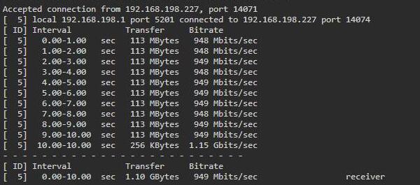
Note: The speed of the native Gigabit network test can be affected by the network environment and the testing method. Speeds should be considered based on actual results; this test is for reference only.
5.3 4G in/Gigabit Ethernet out internet connect test
Make sure the 4G module is connected to the expansion board.
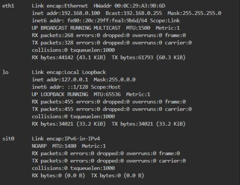
After entering the OpenWrt system, as previously mentioned, connect the expansion board's Ethernet port directly to the PC's Ethernet port using an Ethernet cable. At this point, when we execute ifconfig -a in the "System - TTYD Terminal," we can see the parameters of eth1 (4G module, if it is a Qualcomm 4G module, it will be recognized as usb0.):
Then go to "Network - Interfaces" and click on "Add New Interface":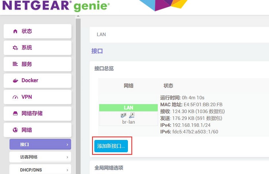
The setup for the new interface is as shown in the following figure, where "eth1" refers to the 4G module:
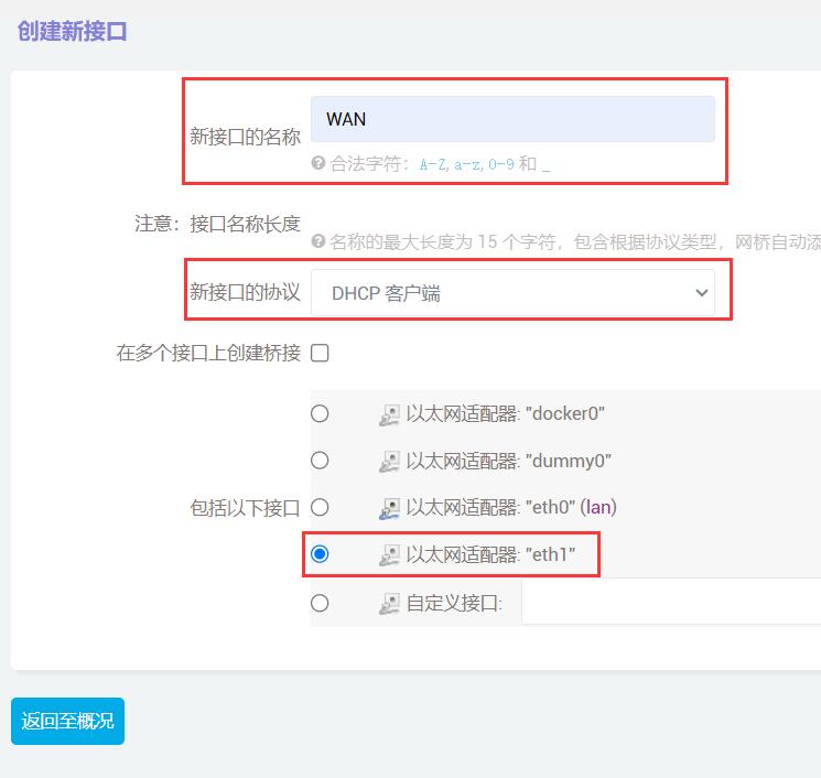
Then click "Submit."
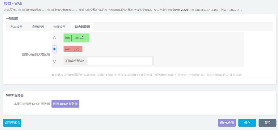
In the "Firewall Settings", select "wan", and then click "Save & Apply":
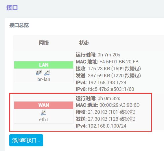
Wait a moment, we will be able to see that the WAN port has obtained an IP address via the 4G module in the "Network - Interfaces" section:
Go to "System - TTYD Terminal," and if you can successfully ping public IP addresses, it indicates that you can now access the internet through the 4G module:
At the same time, we can see in the network connection of the PC connected to the expansion board that the Ethernet connection status is Internet, indicating that the PC can also access the internet through this 4G module:

5.4 WiFi in/Gigabit Ethernet out internet connect test
This test requires a Raspberry Pi CM4 core board with a WiFi module.
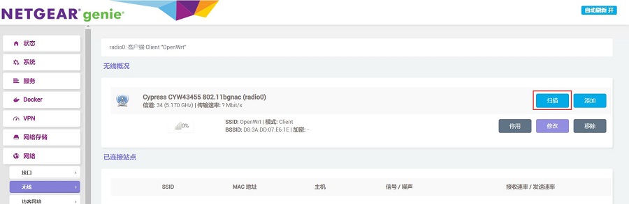
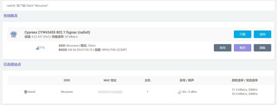
After entering the OpenWrt system, as previously mentioned, connect the expansion board's Ethernet port directly to the PC's Ethernet port using an Ethernet cable. Then go to "Network - Wireless" and click "Scan":
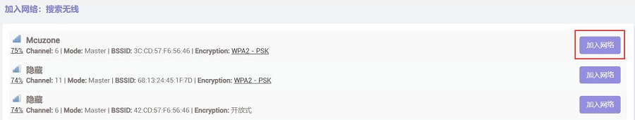
Join a wireless network:
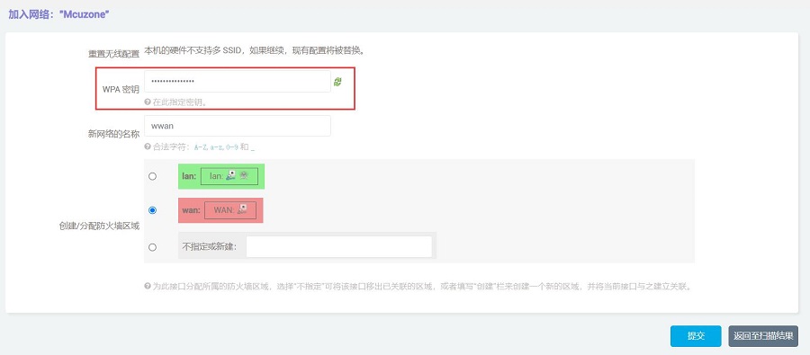
Then click "Submit", and on the next page, click "Save & Apply":

Wait a moment, and we will then be able to see in "Network - Wireless" that this wireless network card has successfully connected to the network:
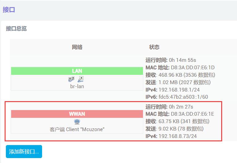
Then go to "Network - Interfaces", where we can see that this WWAN port has already obtained an IP address:
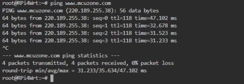
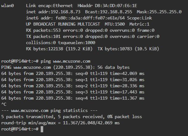
Go to "System - TTYD Terminal," and if you can successfully ping public IP addresses, it indicates that you can now access the internet through the 4G module:
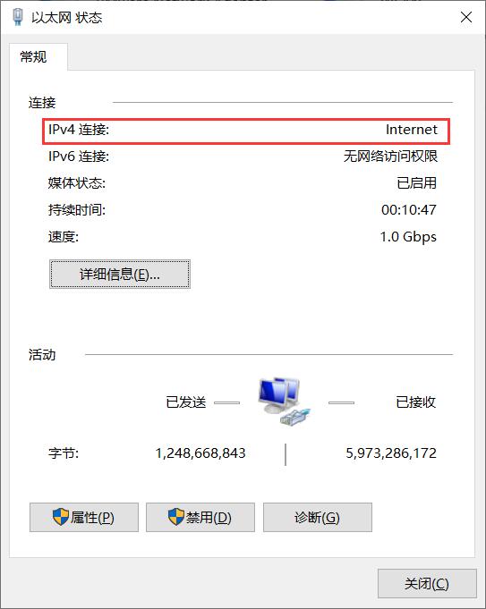
At the same time, we can see in the network connection of the PC connected to the expansion board that the Ethernet connection status is Internet, indicating that the PC can also access the internet through this 4G module:
Contact Us


 QQ:8204136
Email: mcuzone@vip.qq.com
Tel: +86(0)13957118045
If there are any omissions, errors, or infringements on this page, please contact us through the above methods. Thank you!
Copyright 2004-2025 Wildchip