0020 MPU4G(PCIe to USB 4G LTE EN
Keywords
Raspberry Pi 5, Raspberry Pi, 4G LTE, PCIe, mini PCIe, AT Commands
I. Introduction
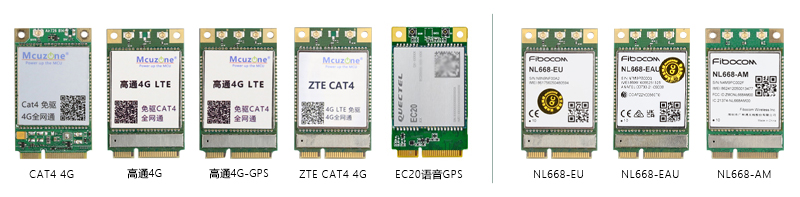
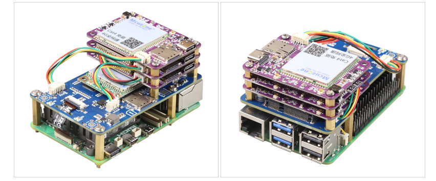
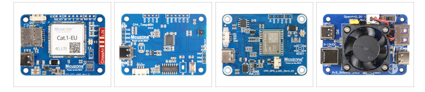
The MPU4G is a 4G expansion board specifically designed for the Raspberry Pi 5. First, expand four USB 2.0 interfaces through the PCIe interface, then connect one of the USB 2.0 signals to the 4G module on the miniPCIe interface. The remaining three USB 2.0 interfaces are brought out in the form of a 1.25mm 4Pin connector. These three interfaces can be used to further expand 1-3 CM4-sized 4G modules. When expanding more than two 4G modules, please pay attention to the power supply. They can also be used to expand our temperature and humidity modules or GPS modules. The 4G modules included with the expansion board are driver-free and do not require dial-up. They are automatically recognized and plug-and-play under the Raspberry Pi official OS/Ubuntu, eliminating the need for additional driver installation. Their target applications include 4G access, multi-4G carrier aggregation, and remote unattended operation.
The MiniPCIe 4G models are as follows: Domestic solution CAT4 4G and ZTE CAT4 4G, Quectel EC20 Voice GPS Lite version (with call and SMS functions), Qualcomm 4G, and Qualcomm 4G-GPS version. There are also international versions, such as the Qualcomm 4G European version (NL668-EU), Australian version (NL668-EAU), and North American version (NL668-AM), among others.
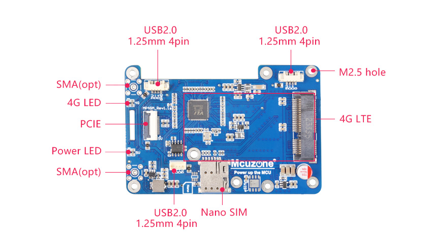
II. Hardware Spec
1. One PCIe interface, 0.5mm 16P, used to connect to the Raspberry Pi 5's own PCIe interface, and PCIe expands to 4 USB ports.
2. One Mini PCIe 4G LTE interface.
3. One Nano SIM card slot, single SIM single standby.
4. Triple-channel USB 2.0 interface, 1.25mm-4P, can be used to expand 1-3 channels of 4G.
5. Two LED lights, one serving as the power indicator and the other as the 4G status light.
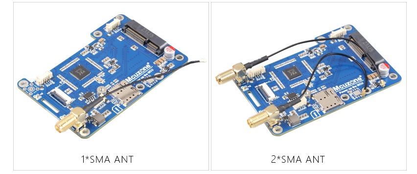
6. Reserve two 4G SMA antenna interfaces.
7. Reserve two 4G SMA antenna interfaces.
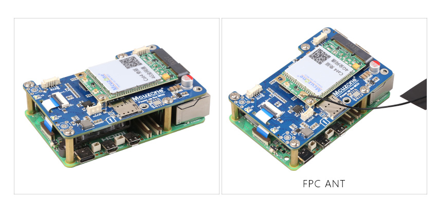
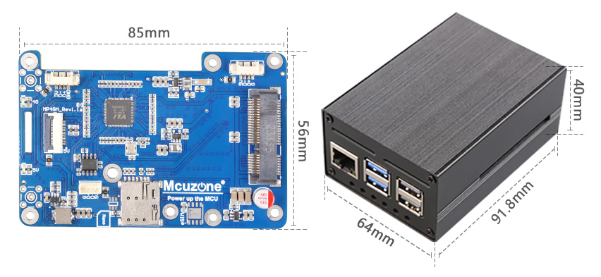
8. Size: 85*56mm. Fully compatible with the Raspberry Pi 5 in terms of size and mounting holes. The board features a grooved design that does not interfere with the GPIO of the Raspberry Pi 5.
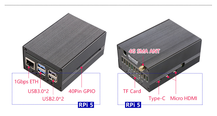
9. Aluminum alloy casing(OPT.)
| CAT4 | 高通4G/GPS | ZTE CAT4 | EC20-GPS简版 | |
|---|---|---|---|---|
| BAND | LTE FDD:B1/3/5/8
LTE TDD:B34/38/39/40/41 |
LTE FDD:B1/3/5/8
LTE TDD:B34/38/39/40/41 WCDMA:B1/8 TDSCDMA:B34/39 EVDO/CDMA1X:BC0 GSM/GPRS/EDGE:900/1800MHz(OPT) |
LTE FDD:B1/3/5/8
LTE TDD:B34/38/39/40/41 |
LTE FDD:B1/3/5/8
LTE TDD:B34/38/39/40/41 WCDMA:B1/8 TDSCDMA:B34/39 CDMA:BC0 GSM:900/1800MHz |
III. Work with Raspberry Pi OS
Raspberry Pi OS: 2024-07-04-raspios-bookworm-arm64.img.xz
You can download it in:
https://www.raspberrypi.com/software/operating-systems/#raspberry-pi-os-64-bit
Different 4G models recognize different device models, usually as eth1 or usb0 devices.
3.1 Qualcomm 4G module
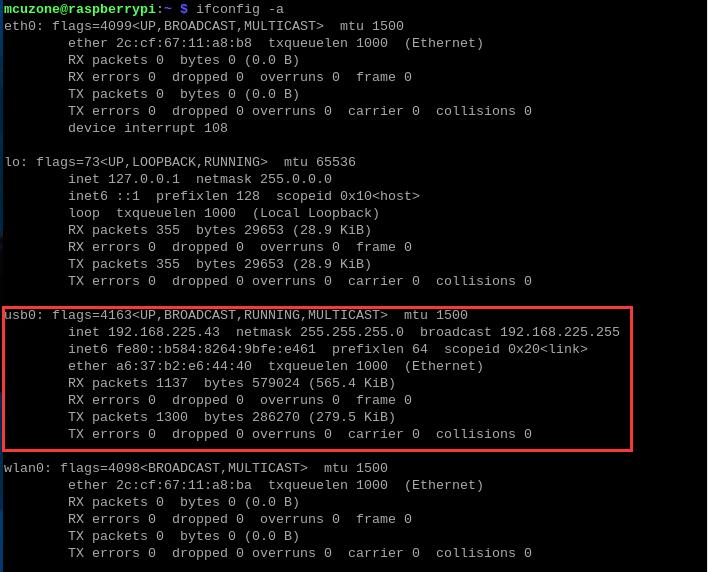
By executing ifconfig -a in the Raspberry Pi terminal, we can see that the 4G module (usb0) has successfully obtained an IP address.
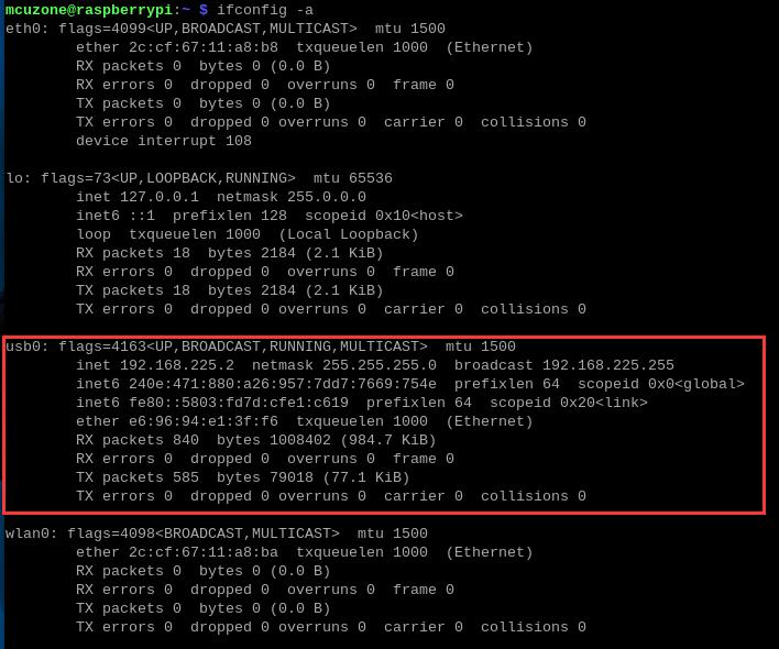
Under normal conditions, the "4G" LED indicator on the expansion board will blink slowly, with occasional brief fast flashes in between.
3.2 CAT4 4G module
By executing ifconfig -a in the Raspberry Pi terminal, we can see that the 4G module (eth1) has successfully obtained an IP address.
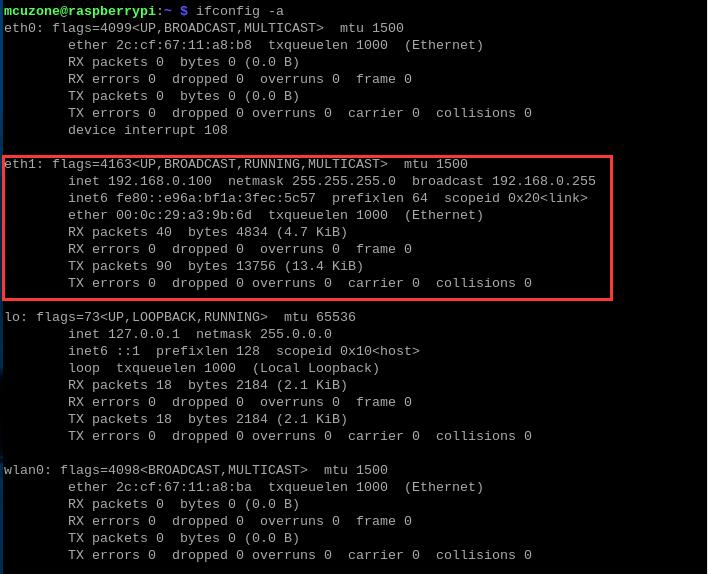
Under normal conditions, the "4G" LED indicator on the expansion board will blink slowly (the duration of the light being on is longer than the duration of it being off).
3.3 ZTE CAT4 4G module
By executing ifconfig -a in the Raspberry Pi terminal, we can see that the 4G module (eth1) has successfully obtained an IP address.
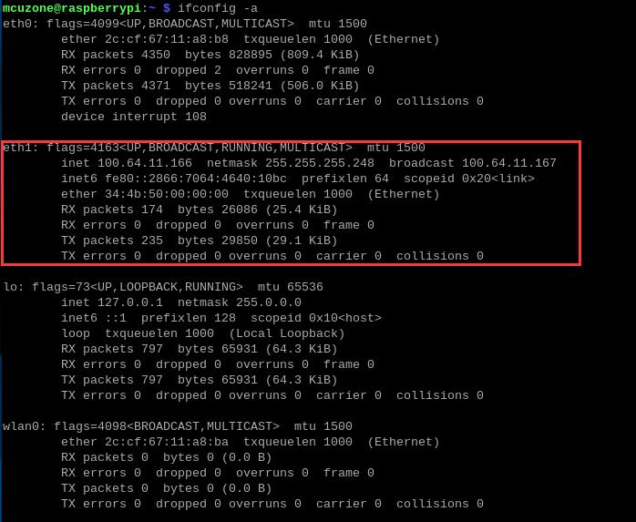
Under normal conditions, the "4G" LED indicator on the expansion board flashes rapidly."
3.4 Quectel EC20 voice GPS L lite version
By executing ifconfig -a in the Raspberry Pi terminal, we can see that the 4G module (usb0) has successfully obtained an IP address.
Under normal conditions, the "4G" LED indicator on the expansion board will blink slowly.
3.5 Internet test
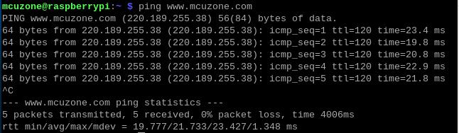
After the 4G module successfully obtains an IP address, we can ping external network addresses, such as:
ping www.mcuzone.com
It is also possible to connect to the external network via a 4G module and access a speed test website to measure the speed, with the results as follows:
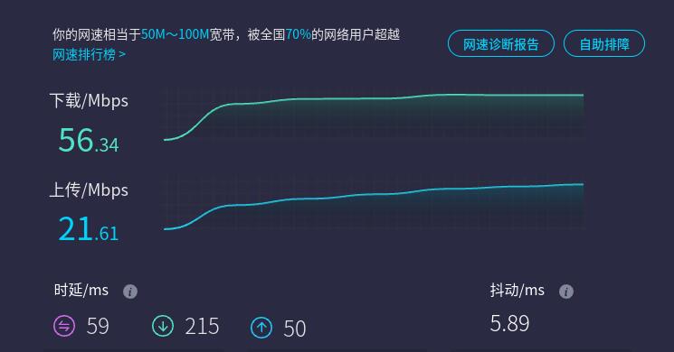
Note: Network speed tests are affected by the network environment and testing methods. Please refer to the actual speed, as this test is for reference only.
3.6 Remote Connection to Raspberry Pi(4G application)
If you want to use 4G for remote access to a Raspberry Pi 5, the official Raspberry Pi OS (Bookworm version) comes with an example application called Raspberry Pi Connect that you can refer to and use. With the Raspberry Pi paired with 4G, and through the official remote control software Raspberry Pi Connect, you can securely access your Raspberry Pi from anywhere in the world. Here, we will demonstrate how to configure the remote connection service.
The configuration and usage instructions are as follows:
1. Apply for a Raspberry Pi ID at https://id.raspberrypi.com/.
2. Install the Raspberry Pi Connect software in the Raspberry Pi OS (no need to install if it is already installed):
sudo apt install rpi-connect
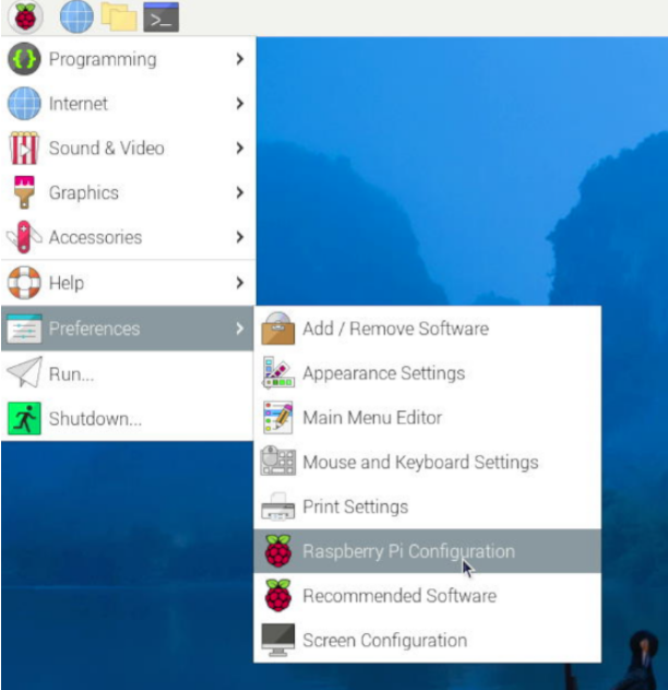
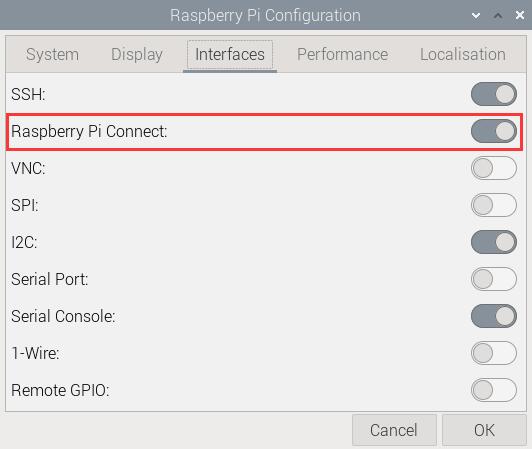
3. Restart the system, and in the GUI, sequentially select the items as shown in the following image to ensure that Raspberry Pi Connect is turned on:
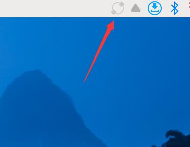
4. In the upper right corner, there will be a Raspberry Pi Connect icon.
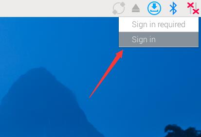
5. Click on this icon, select "Sign in" and use your previously registered Raspberry Pi ID to log in on the pop-up webpage. Then set the device name.
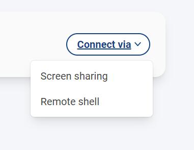
6. After successfully logging in, access https://connect.raspberrypi.com/ in a browser on Windows and log in.
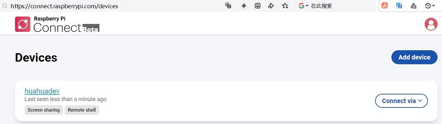
7. Click "Connect via" to choose between using Screen sharing or the Remote shell Interface.
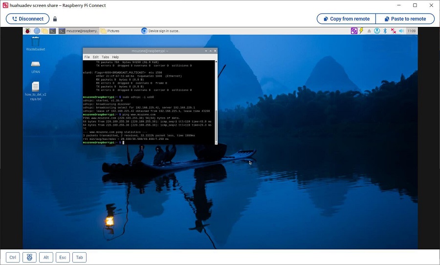
8. Screen sharing is as follows:
The remote command line interface is as follows:
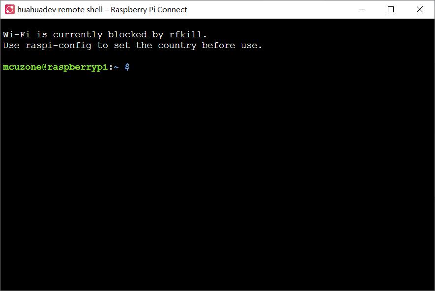
9. Measured data usage: Under remote desktop, the Raspberry Pi consumes about 2MB of data per minute; under The remote shell is as follows: line interface, the Raspberry Pi consumes about 100KB of data per minute.
四、Ubuntu OS的操作
我们测试的Ubuntu OS的版本为:
ubuntu-24.04-preinstalled-desktop-arm64+raspi.img.xz(Desktop版,图形化版本)
ubuntu-24.04-preinstalled-server-arm64+raspi.img.xz(Server版,命令行版本)
Ubuntu OS下载地址:
https://ubuntu.com/download/raspberry-pi
4.1 Ubuntu Desktop系统
Ubuntu Desktop系统(图形化版本),终端执行ifconfig -a时,所有的4G模块均识别为enx开头的网卡,可直接使用,免驱免配置。
4.2 Ubuntu Server OS
Ubuntu Server系统(命令行版本)基于树莓派5,默认只开启一路网络,而且关闭wifi功能,所以若要用4G或wifi,则需要开启第二路,第三路网络,且需要手动添加网卡才能使用;在此,我们将演示Ubuntu Sever下将wifi开启,且使用4G的操作步骤:
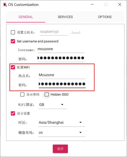
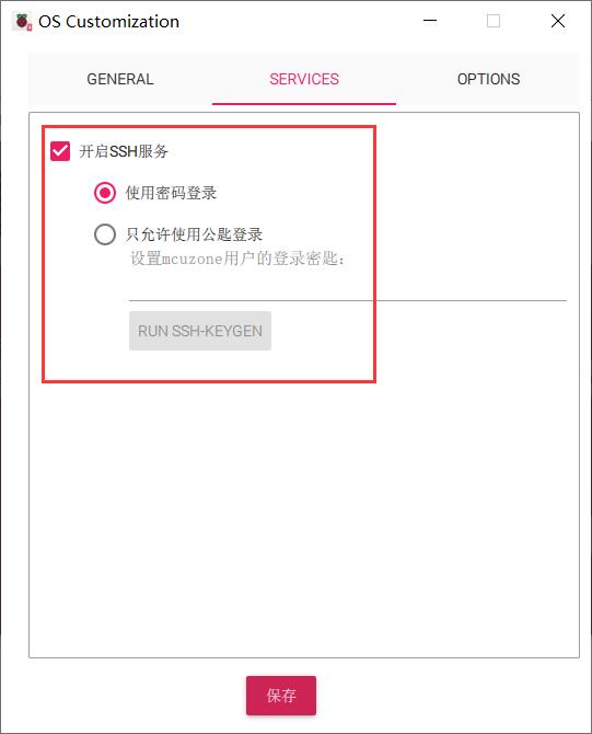
4.2.1 系统烧写,设置SSH
烧写系统时建议在树莓派烧录器里面把WiFi和SSH设置都预设置好:
将TF卡插入树莓派,启动系统。第一次启动后会要求登录,用户名和密码均为ubuntu,登录成功后会要求修改密码。
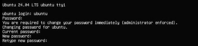
修改完毕后就自动进入系统。
4.2.2 配置系统网络
此处操作以CAT 4G为例。
系统默认并没有集成ifconfig工具,只有ip命令可用。
执行ip addr查看并记录下网卡名称:
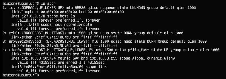
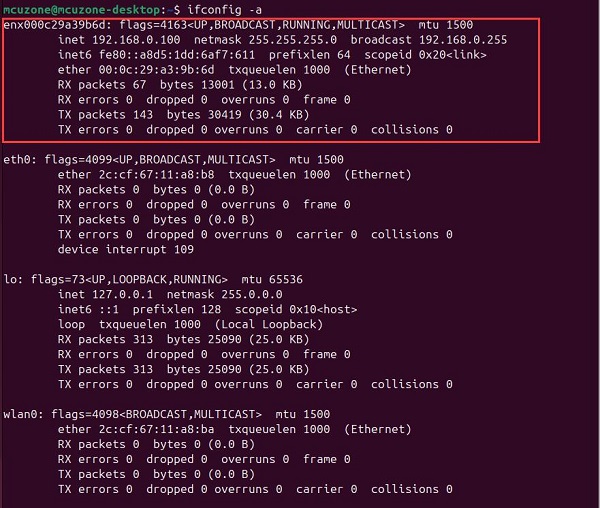
其中eth0树莓派5自带千兆网口,enx000c29a39b6d为4G模组,wlan0为树莓派自身的无线网卡(本系统烧写时已经预配置了无线热点信息,因此启动后即可使用无线网卡)。
然后运行下面的命令,打开网卡配置文件:
sudo nano /etc/netplan/50-cloud-init.yaml
按照下图编辑网卡配置文件:
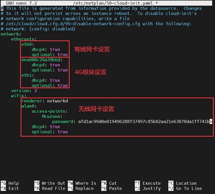
保存退出,然后重启。
重启后即可联网,安装net-tools工具以便于使用:
sudo apt install net-tools
安装完毕net-tools工具,即可使用ifconfig -a查看网络状态:
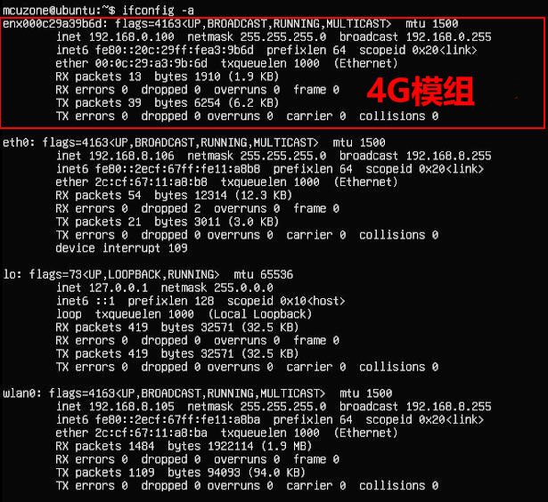
可见此时有线网卡和4G模组均已获取了ip地址。
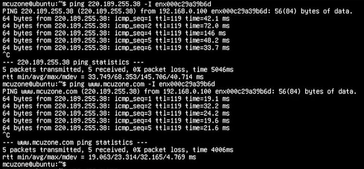
我们通过某一网卡ping外网服务器,即可验证该网卡工作是否正常,如我们通过4G模组ping外网IP和网址,结果如下:
ping 220.189.255.38 -I enx000c29a39b6d
ping www.mcuzone.com -I enx000c29a39b6d
五、AT命令操作
5.1 操作AT命令
此处操作以高通4G模组为例。在树莓派终端中执行命令lsusb,如下图所示:
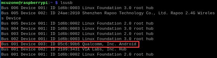
本模块的id为05c6 90b6,记录下这个值。(每个模组的ID号不同,以实际查看为准)
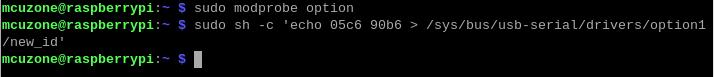
使用下列命令打开ttyUSB串口,其中echo后面的值就是之前记录的ID值:
sudo modprobe option
sudo sh -c 'echo 05c6 90b6 > /sys/bus/usb-serial/drivers/option1/new_id'
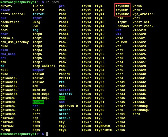
执行上述两条命令之后执行:
ls /dev
此时应该能看到dev设备下有ttyUSB0-2三个设备:
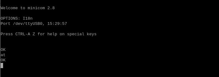
然后通过minicom打开AT命令串口:
sudo minicom -D /dev/ttyUSB0

(注意:使用哪个串口,应以在进入此串口后,可输入运行AT命令,显示不乱码,不乱跳结果为准)
第一次输入AT命令可能没有回显,此时如果输入命令at后回车,有返回OK,就说明工作正常。如果需要查看回显,请键入命令:ate1,然后回车,继续键入其它命令,回车可以看到结果。
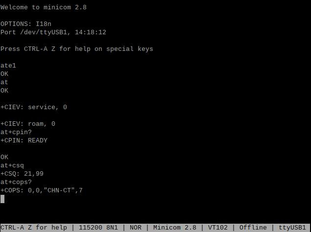
5.2 常用AT命令
1) 检查SIM卡是否识别到:
at+cpin?
返回ready表示卡已识别,返回error要检查硬件
2) 检查天线信号质量:
at+csq
返回值在26-31表示信号OK,信号满格31;返回值在20-25表示信号勉勉强强;返回值在20以下表示信号比较糟糕或者天线没接
3) 检查注网情况:
at+cops?
正常应该返回运营商代码和7,7代表4G。
注意,以上命令只有at+csq不要加问号,另外两条命令需要加问号。
4) 查看4G模块的IMEI码:
at+cgsn
5) 重启4G模块(有时候如果重插SIM卡,热插拔不一定管用,可以用这个reset命令来复位模块):
at+reset
6) 关闭射频:
at+cfun=0
开启射频:
at+cfun=1
上述两条命令成对使用,可以在不重启4G模组的情况下让模组重新注网。
7)APN设置
普通手机SIM是不需要任何设置,即可直接使用,有些物联网卡需要设置APN才能正常使用,APN的参数一般由运营商提供,以下仅供参考。
移动卡:
AT+CPNETAPN=0,"cmnet","",""
电信卡:
AT+CPNETAPN=0,"ctnet","",""
如果你需要其它AT命令的操作方法,请自行查看4G模组配套的at命令手册(各个厂家的模块的操作命令不尽相同)。
5.3 修改IP地址方法
如果出厂的4G IP地址和用户使用的IP地址有冲突,或有修改IP地址的需求,可按照下列步骤进行修改:
CAT4 4G:
执行AT命令:
AT+ROUTEIP=<newip>
注意,只支持192.168.x.1这样格式的地址,如果设置了AT+ROUTEIP=192.168.3.1,最终获得的IP为192.168.3.100,修改完后需断电重启系统。
查询当前IP:AT+ROUTEIP?,返回两个值,前一个为旧IP,后一个为新IP。
测试命令:AT+ROUTEIP=?
高通 4G模块、ZTE CAT4模块:
将4G模块的IP改为直接获取公网IP即可,请执行AT命令:
设置IP为公网:AT+GTIPPASS=1
设置IP为内网:AT+GTIPPASS=0
查询当前IP为公网还是内网:AT+GTIPPASS?
修改IP完毕后需要断电重启才能生效。
EC20的IP地址不清楚如何修改,如有需要,需要用户自行研究。
5.4 GPS的使用
5.4.1 高通4G-GPS
若要使用高通4G的GPS功能,需要接GPS无源天线,且确保GPS天线甩出户外。GPS是通过AT命令操作。
按照章节5.1步骤,开启ttyUSB串口。
运行minicom,打开ttyUSB0串口:
sudo minicom -D /dev/ttyUSB0
并运行:
at+gtgpsepo=1 //开启AGPS
at+gtgpspower=1 //打开GPS
稍等片刻待定位成功,运行:
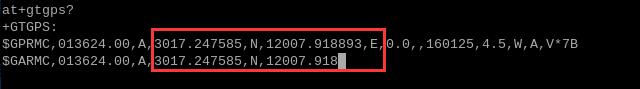
at+gtgps? //查看NMEA信息
就可以看到GPS信息输出:
5.4.2 EC20-GPS语音简版
5.4.2.1 GPS的操作
使用EC20的GPS,需要接GPS有源天线,且确保GPS天线甩出户外,GPS是通过AT命令操作。
开启ttyUSB串口。然后运行minicom,打开ttyUSB3串口:
sudo minicom -D /dev/ttyUSB3
并运行:
AT+QGPS=1
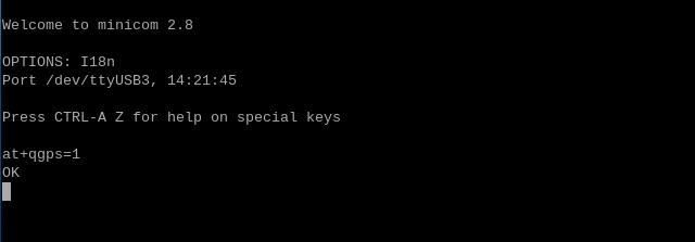
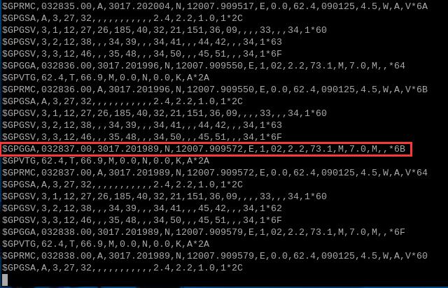
运行minicom,打开ttyUSB1串口,即可获取GPS信息:
sudo minicom -D /dev/ttyUSB1
如果觉得minicom下看原始的GPS信息不太直观,那么我们可以安装gpsd来提取GPS信息:
sudo apt-get install gpsd gpsd-clients

然后配置gpsd软件:
sudo gpsd /dev/ttyUSB1 -N -D 9 -F /var/run/gpsd.sock -S 3333

注:3333为监听端口,可自行定义。
不要关掉配置终端窗口,另外开一个终端窗口,运行:
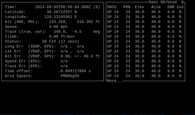
cgps -s localhost:3333

从输出的界面可以看到时间、经纬度、速度、高度等信息:
5.4.2.2 发短信操作
发短信是使用AT命令操作,这里介绍使用英文字符发送短信的流程。
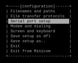
按照章节5.1步骤,开启ttyUSB串口,然后运行sudo minicom -s,选择“Serial port setup”:
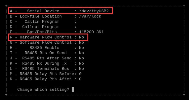
按A和F ,修改串口号和流控如下图所示:
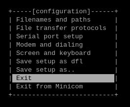
修改完毕后按回车返回上一层菜单,选择“Exit”退出:
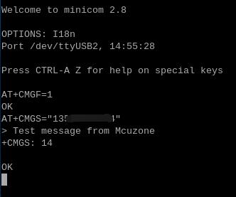
依次执行下列AT命令:
AT+CMGF=1 //将短信字符设置为英文
AT+CMGS="13xxxxxxxxx" //设置接收短信的号码
回车后在>后面输入短信内容,然后按Ctrl+Z发送,发送成功会显示“+CMGS 14”:

5.5 关于网络策略的一些知识
若您需要了解一些网络策略知识,可以参考如下链接:
六、OpenWrt的操作
我们测试用的OpenWrt系统版本为:openwrt-bcm27xx-bcm2712-rpi-5-squashfs-sysupgrade-linux-6.1.100-20240805.img.gz
以高通4G模组为例,OpenWrt系统下可配置为一进一出的交换机模式,即4G可作为WAN口,树莓派5自身的网口配置为LAN口,用于连接PC。
6.1 登录操作界面
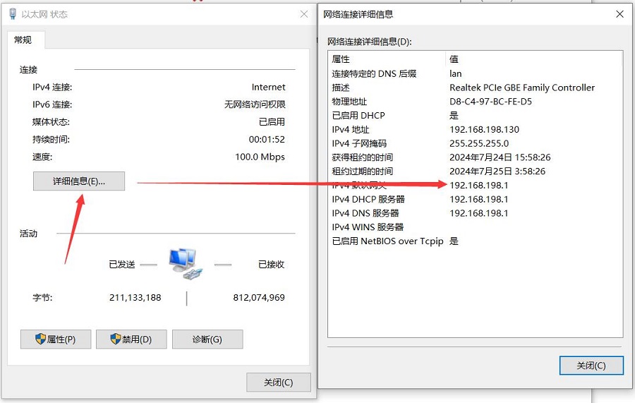
将树莓派5连接至PC网口,启动系统,在Windows设置中找到网络和Internet,在以太网中打开连接的网络查看默认网关的IP地址,这个地址就是OpenWrt系统的后台配置页面地址,如图所示,本文测试的地址为192.168.198.1:
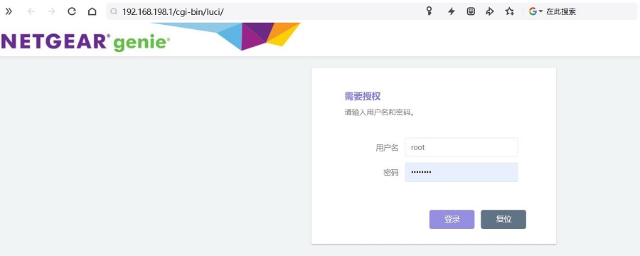
然后打开网页浏览器输入192.168.198.1进入OpenWrt系统。默认用户名为root,默认密码为password。
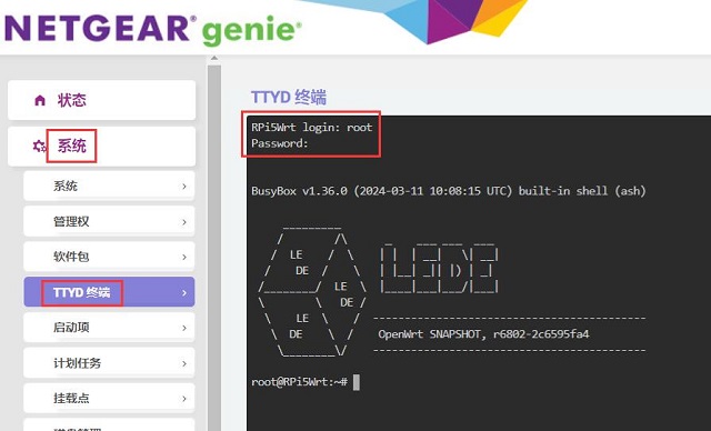
登录后进入“系统 - TTYD终端”,使用用户名为root、密码为password进行登录:
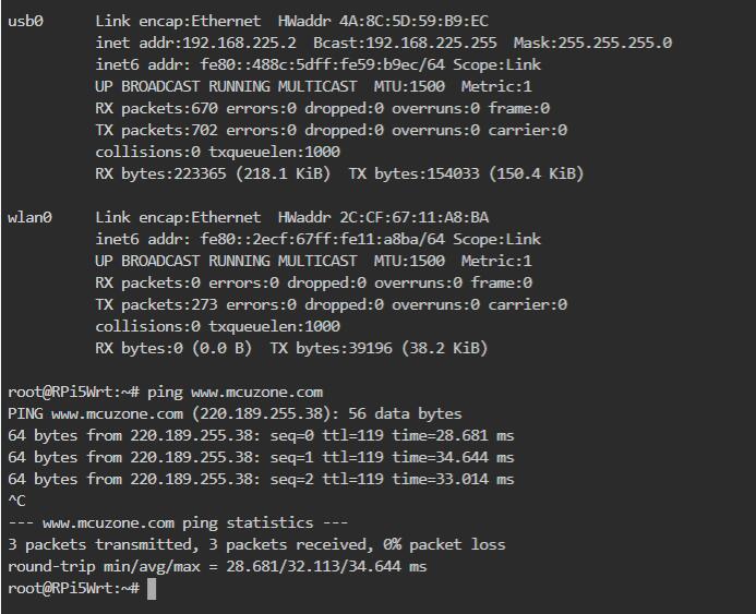
输入ifconfig -a,可以看到有标识为usb0的网卡,即为高通4G模组:
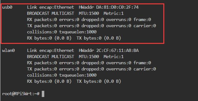
若是国产CAT4或ZTE CAT4,系统识别成eth1,若是EC20也是识别成USB0,到时设置接口时,把usb0改成eth1即可。
6.2 设置4G为WAN口
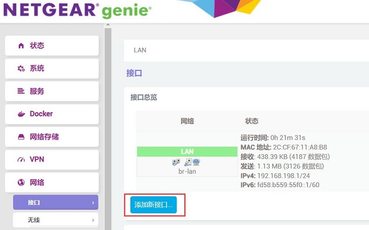
进入OpenWrt系统后,然后进入“网络 - 接口”,点击“添加新接口”:
新接口的设置如下图,其中”usb0“即为4G模块:
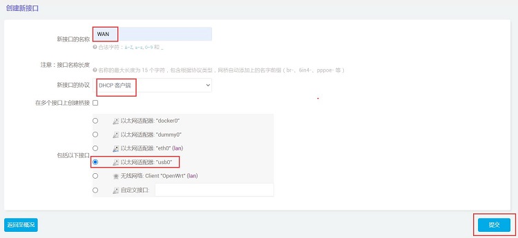
然后点击”提交“。
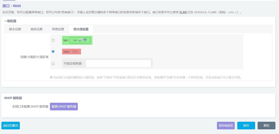
在”防火墙设置“中,区域选择”wan“,然后点击”保存&应用“:
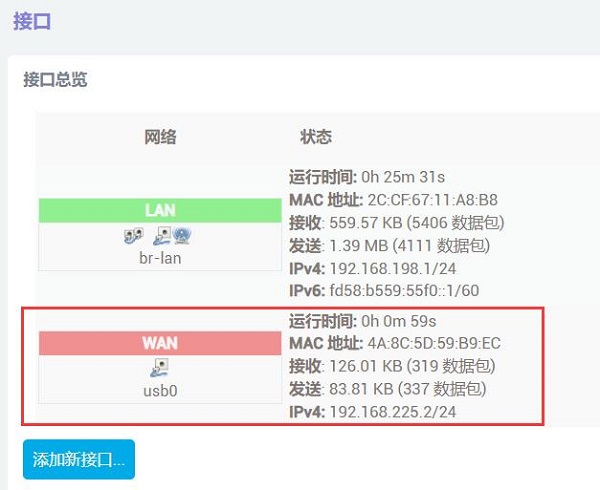
稍等片刻,我们在”网络 - 接口“中就能看到WAN口已经通过4G模块获得了IP:
此时我们在“系统 - TTYD终端”中,执行ifconfig -a,就能看到usb0已成功获取IP地址,ping公网地址也能成功,说明此时可以通过4G模块上网:
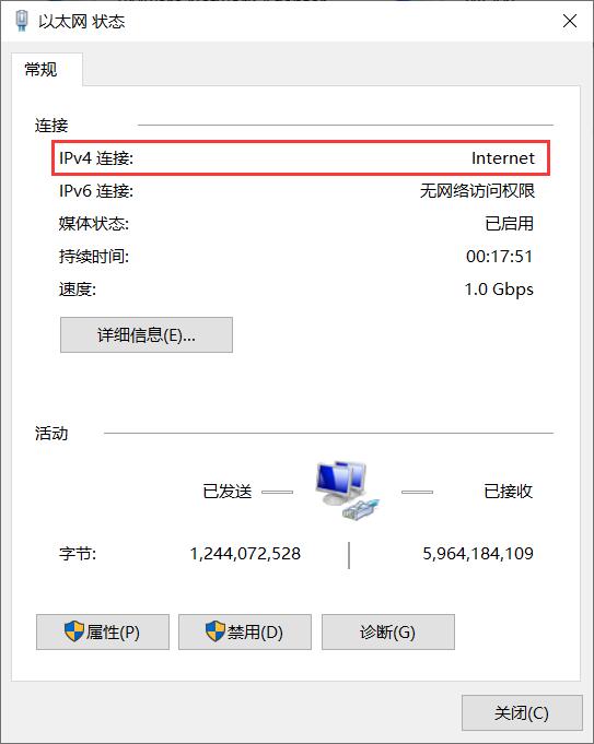
同时我们可以在与树莓派相连的PC的网卡连接中,看到以太网的连接状态是Internet,表示此时PC也可以通过这个4G模组上网:
在PC端打开https://www.speedtest.cn/进行测速,此时流量走的是4G模块,测试结果如下:
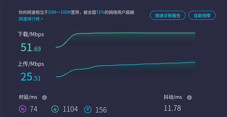
注意:4G网络测速受网络信号和测试方法影响,速度请以实际为准。
联系我们


 QQ:8204136
电话:13957118045
如本页面有任何疏漏、错误或者侵权,请通过上述途径联系我们,谢谢!
Copyright 2004-2025 野芯科技