0024 M4GUSB EN
Change the language to English
Keywords
4G LTE, CAT4, EC20, Qualcomm 4G, GPS, AT Commands, Raspberry Pi OS, Ubuntu, OpenWrt, Driver-free, Plug-and-Play
I. Introduction
The M4GUSB is a 4G module expansion board specifically designed for the Raspberry Pi 5. It is driver-free, requires no dial-up, and is automatically recognized and Plug-and-Play on the official Raspberry Pi OS, Ubuntu, and OpenWRT. The 4G LTE is a USB device designed based on the Raspberry Pi's USB port, with optional GPS functionality. Some 4G models support VoLTE for sending text messages and making phone calls (but without audio). The EC20-GPS also supports making phone calls (requires an Android headset cable) and sending text messages. The 4G module we use has a CAT4 speed, with theoretical speed values of 150Mbps (DL)/50Mbps (UL). The 4G module is also compatible with Raspberry Pi 4B/3B.
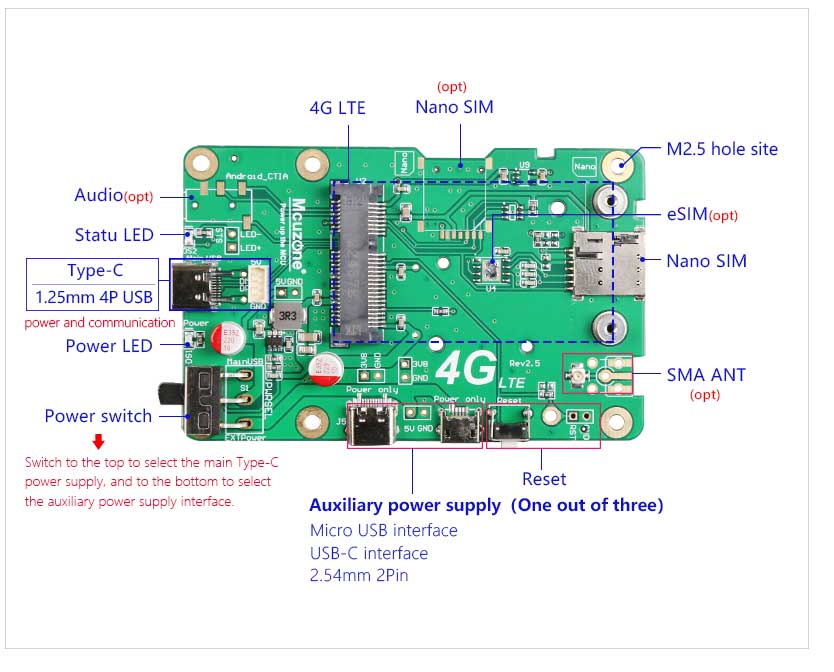
II. Hardware Spec
1. One USB-C port is provided, and a 1.25mm 4P interface is also provided. This interface serves as both the communication interface and the power supply interface, allowing the 4G module to operate without requiring additional power.
2. Equipped with three auxiliary power supply interfaces: USB-C, MicroUSB, and a 2-pin header auxiliary power supply interface (if the Raspberry Pi's own peripherals are numerous, causing insufficient power supply from the Raspberry Pi's USB port to the 4G module, the 4G module can independently draw power through the auxiliary power supply interface, controlled by a power switch).
3. A power switch that allows for quick physical disconnection when 4G connectivity is not needed.
4. One MiniPCIe interface for connecting a 4G LTE module.
5. One Nano SIM card slot, packaged as 5*6mm, with reserved solder pads, not pre-soldered, requires users to purchase and solder themselves.
6. Reserve a slot for a Nano SIM card.
7. A 4G reset button is provided along with reserved reset pins and pogo pin interfaces, allowing for manual reset or reset of the 4G module via GPIO.
8. 1st generation IPEX connector, compatible with various antenna assembly methods.
9. Onboard 2.54mm-2P 3.3V power interface, which can be used to assemble a side turbo fan (located on the reverse side of the drive board) for cooling the Raspberry Pi.
10. Reserve an analog audio headphone jack for making phone calls (only supported by our EC20-GPS Voice Lite version, compatible with Android headphone cables).
11. Size: 85*56mm;
12. The circuit board employs immersion gold technology and is produced using lead-free processes. The PCB board is UL and ROHS certified, with a flammability rating of 94V-0.
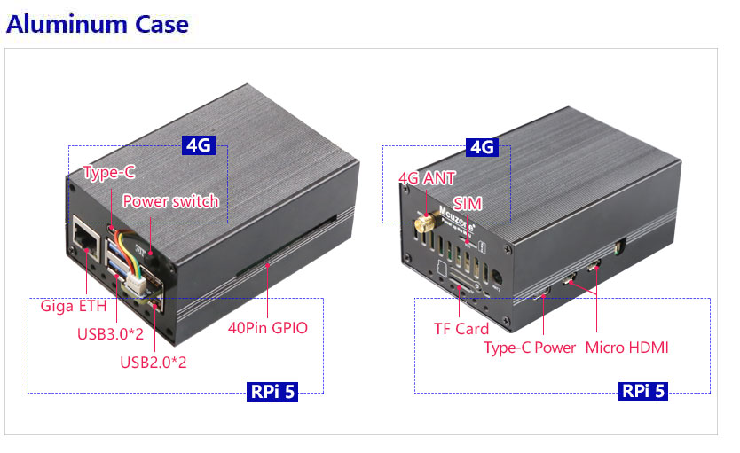
13. Aluminum alloy casing(OPT.)
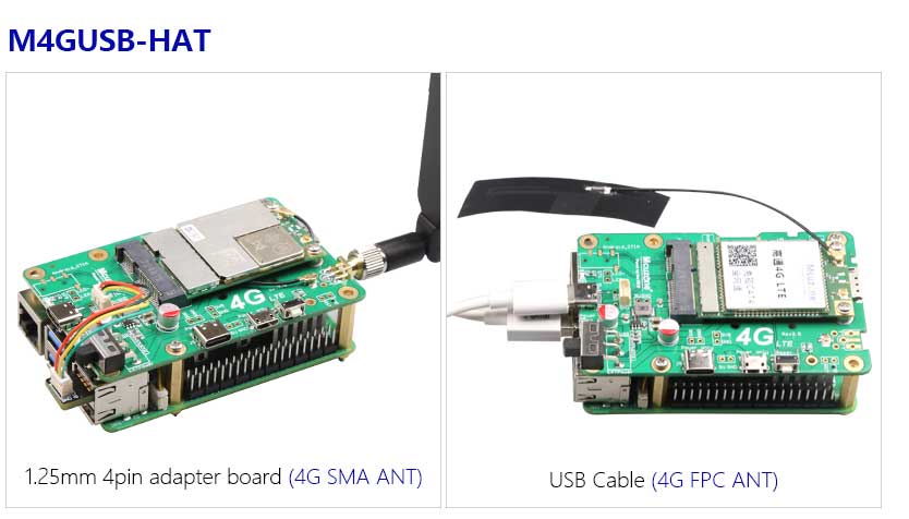

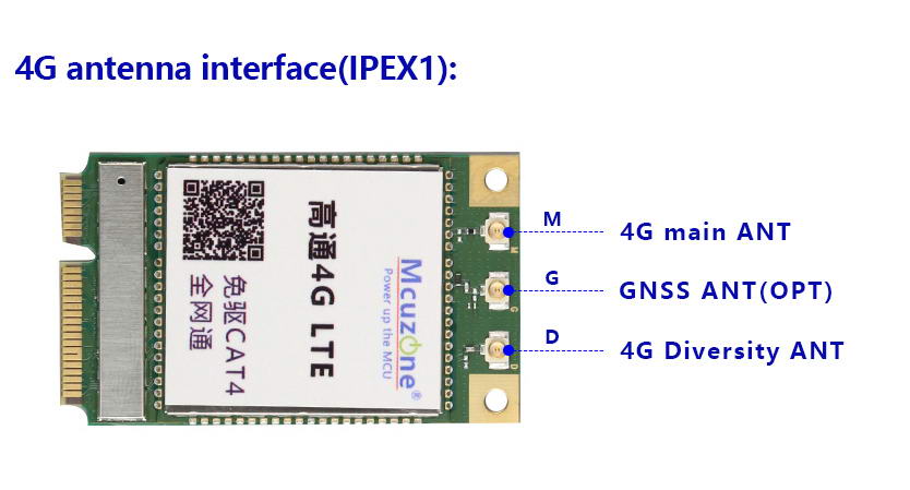
Antenna connection instructions for 4G modules, applicable to all 4G modules tested in this document (GPS/GNSS is optional):
3.1 OS version for test
1. Raspberry Pi OS: 2024-07-04-raspios-bookworm-arm64.img.xz
You can download it in:
https://www.raspberrypi.com/software/operating-systems/#raspberry-pi-os-64-bit
2. Ubuntu OS: ubuntu-24.04-preinstalled-desktop-arm64+raspi.img.xz
You can download it in:
https://ubuntu.com/download/raspberry-pi
3. The OpenWrt was compiled by Mcuzone, and the version is: openwrt-bcm27xx-bcm2712-rpi-5-squashfs-sysupgrade-linux-6.1.100-20240805.img.gz
3.2 Common AT commands
1. Check if the SIM card is detected:
at+cpin?
Return ready to indicate the card has been recognized, if return error, you need to check the hardware.
2. Check antenna signal quality:
at+csq
eturn values between 26 and 31 indicate a good signal, with 31 representing a full signal strength; return values between 20 and 25 indicate a barely acceptable signal; return values below 20 indicate a poor signal or that the antenna might not be connected.
3. Check network registration status:
at+cops?
Normally, it should return the network supporter's code: 7, where 7 represents 4G.
Note: The above command at+csq should not include a question mark, while the other two commands require a question mark.
4. View the SIM card's IMEI code:
at+cgsn
5. Reset 4G module (Sometimes, if you reinsert the SIM card, hot swapping may not work; in such cases, you can use this reset command to reset the module.):
at+reset
6. Disable radio frequency:
at+cfun=0
Enable radio frequency:
at+cfun=1
The two commands mentioned above can be used in pairs to allow the module to re-register with the network without restarting the 4G module.
3.3 AT command documentation download URL
CAT4 4G:
http://www.mcuzone.com/wiki/0024_MP4GUSB/Luat4G_AT_V4.3.5.pdf
Qualcomm 4G(GPS):
http://www.mcuzone.com/wiki/0024_MP4GUSB/NL_AT_User_Manual_V1.0.0_Draft.pdf
ZTE CAT4:
http://www.mcuzone.com/wiki/0024_MP4GUSB/L716-CN-10_AT_User_Manual.pdf
IV. Work with Raspberry Pi OS
4G module is automatically recognized in the Raspberry Pi OS, requiring no drivers or dial-up. CAT4 4G is recognized as an eth device in the OS, while Qualcomm 4G and EC20 are recognized as usb0 devices.
4.1 Qualcomm 4G (with GPS opt.)
4.1.1 Module connection
After starting Raspberry Pi OS, execute lsusb, as shown in the following image:
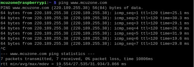
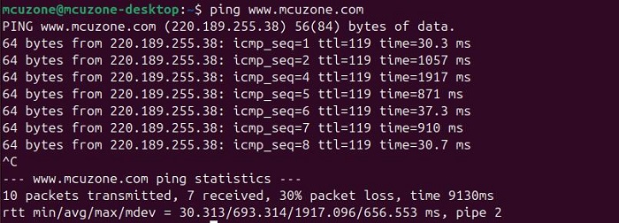
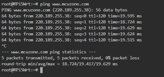
From the image above, we can see that the 4G module (usb0) has successfully obtained an IP address. We can now ping external network addresses, such as:
ping www.mcuzone.com
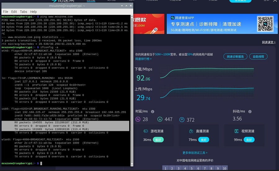
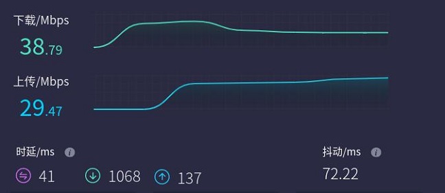
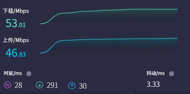
It is also possible to connect to the external network via a 4G module and access a speed test website to measure the speed, with the results as follows:
Note: Network speed tests are affected by the network environment and testing methods. Please refer to the actual speed, as this test is for reference only.
The status of Status LED:
If the LED is blinking slowly with occasional rapid flashes in between, it indicates that the 4G module has connected to the network. Otherwise, it suggests there might be an issue with the SIM card or the network; please check the SIM card and the antenna.
4.1.2 GPS test
If you have chosen the Qualcomm 4G-GPS version, this 4G module comes with GPS functionality, requiring the connection of a GPS passive antenna, and ensuring that the GPS antenna is extended outdoors. GPS is operated via AT commands.
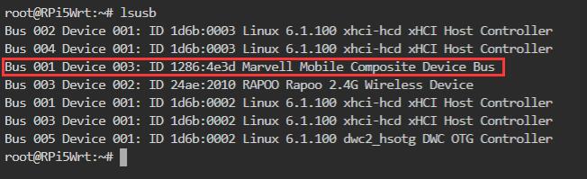
Execute lsusb in terminal:
Record the ID value of the 4G module: 05c6 90b6
Use the following command to open the ttyUSB serial port, where the value after echo is the ID recorded above:
sudo modprobe option
sudo sh -c 'echo 05c6 90b6 > /sys/bus/usb-serial/drivers/option1/new_id'
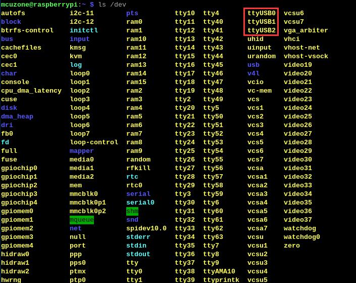
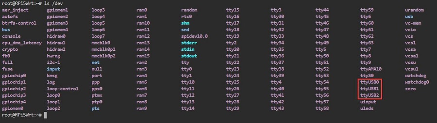
After execution is complete, the system should have four additional devices: ttyUSB0 - ttyUSB2, execute ls /dev to view.
Install minicom:
sudo apt-get install minicom
Open AT Command serial port by minicom:
sudo minicom -D /dev/ttyUSB0
And execute:
at+gtgpsepo=1 //Enable AGPS
at+gtgpspower=1 //Enable GPS
Please wait a moment for the positioning to succeed, then execute:
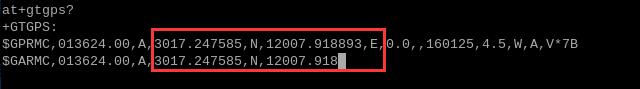
at+gtgps? //View NMEA messages
Then you can see the GPS information output:
4.2 CAT4 4G
By executing ifconfig -a in the Raspberry Pi terminal, we can see that the 4G module (eth1) has successfully obtained an IP address.
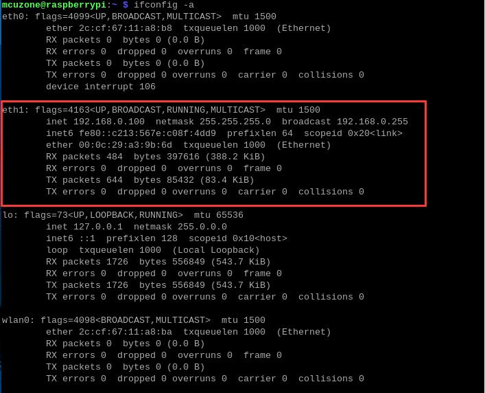
We can ping external network addresses, such as: ping www.mcuzone.com
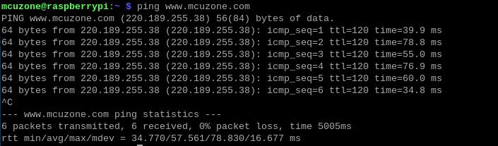
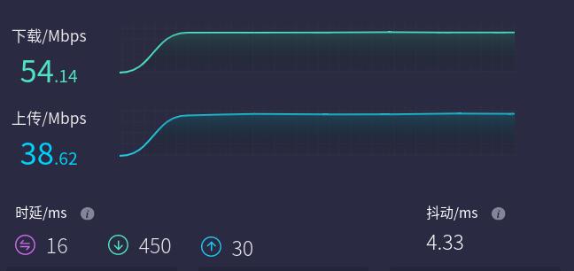
It is also possible to connect to the external network via a 4G module and access a speed test website to measure the speed, with the results as follows:
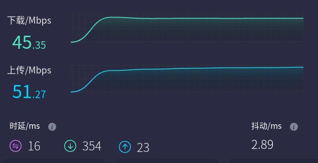
Note: Network speed tests are affected by the network environment and testing methods. Please refer to the actual speed, as this test is for reference only.
The status of Status LED:
The blinking pattern, where the light is on for 1.8 seconds and off for 0.2 seconds (alternatively, you can judge by the light being on longer than it is off), indicates that the 4G module has connected to the network.
The blinking pattern, where the light is off for 1.8 seconds and on for 0.2 seconds, indicates that there is an issue with the SIM card or the network. Please check the SIM card and the antenna.
4.3 ZTE CAT4 4G
By executing ifconfig -a in the Raspberry Pi terminal, we can see that the 4G module (eth1) has successfully obtained an IP address.
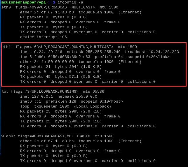
We can ping external network addresses, such as: ping www.mcuzone.com
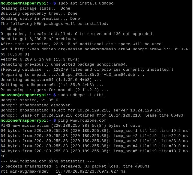
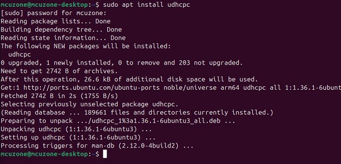
If the server name cannot be found, please install udhcpc:
sudo apt install udhcpc
Please execute the following after successful installation:
sudo udhcpc -i eth1
then ping:
It is also possible to connect to the external network via a 4G module and access a speed test website to measure the speed, with the results as follows:
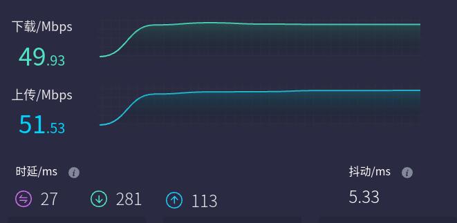
Note: Network speed tests are affected by the network environment and testing methods. Please refer to the actual speed, as this test is for reference only.
The status of Status LED:
If the LED is rapid flashes, it indicates that the 4G module has connected to the network. Otherwise, it suggests there might be an issue with the SIM card or the network; please check the SIM card and the antenna.
4.4 EC20-GPS voice simplified version
4.4.1 Module connection
Currently (after 2024), the EC20 modules we ship are pre-configured to be driver-free in the Raspberry Pi OS, offering plug-and-play functionality with automatic recognition. Connecting the EC20 to a Raspberry Pi for dial-up internet access is also possible, but it is quite complex and cumbersome. Additionally, settings need to be configured every time the system starts, making it not recommended for use. Below are the tests conducted when set to driver-free mode:
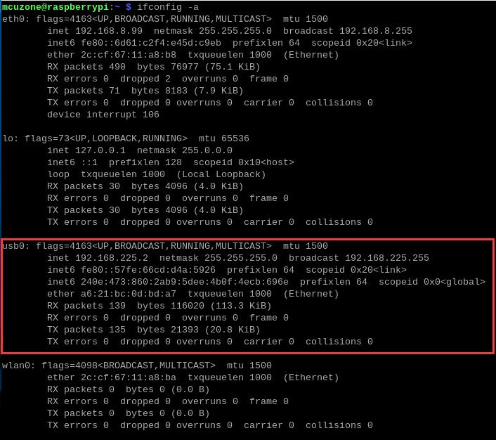
Executing ifconfig -a in the Raspberry Pi terminal:
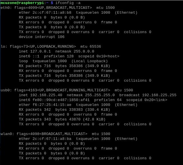
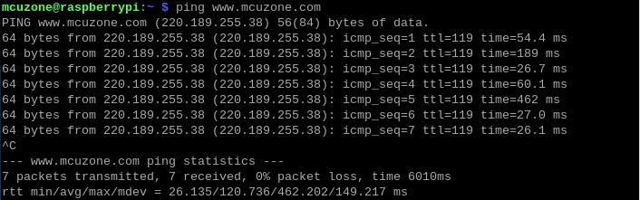
You can see that the OS recognizes the EC20 as the usb0 device and has obtained an IP address. We can ping external network addresses, such as: ping www.mcuzone.com
If the server name cannot be found, please install udhcpc:
sudo apt install udhcpc
Please execute the following after successful installation:
sudo udhcpc -i eth1
Then proceed to perform the ping operation.
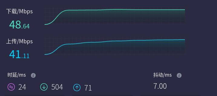
The speed test of the 4G module, connecting to the external network, and accessing the speed test website to measure the speed, with the results as follows:
Note: Network speed tests are affected by the network environment and testing methods. Please refer to the actual speed, as this test is for reference only.
4.4.2 Send SMS
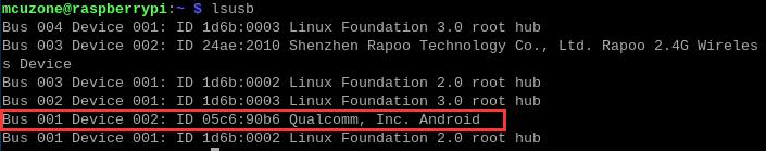
Sending text messages involves using AT commands. Here, we will introduce the process of sending SMS using English characters. Before using AT commands, you need to open the serial port. Execute the command lsusb in the Raspberry Pi terminal, as shown in the following image:
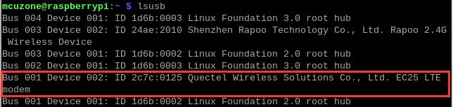
Record the ID value of the 4G module: 2c7c 0125
Use the following command to open the ttyUSB serial port, where the value after echo is the ID recorded above:
sudo modprobe option
sudo sh -c 'echo 2c7c 0125 > /sys/bus/usb-serial/drivers/option1/new_id'
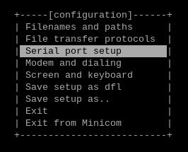
Then execute sudo minicom -s, select "Serial port setup":
Press A and F to modify the serial port number and flow control as shown in the figure below:
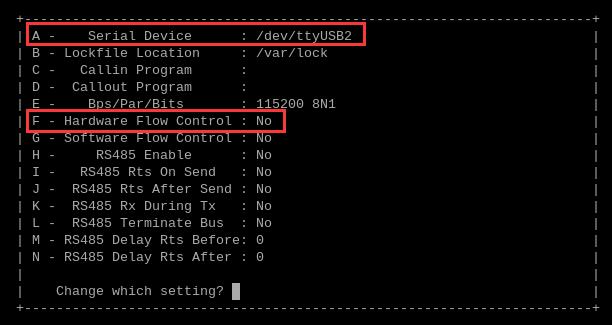
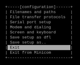
After making the modifications, press Enter to return to the previous menu, and select "Exit" to quit:
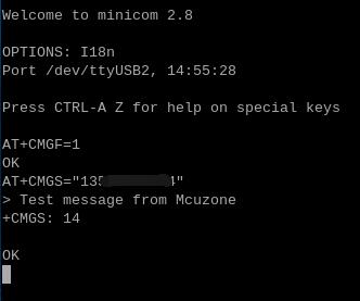
Execute the following AT commands in sequence:
AT+CMGF=1 //Set the SMS characters to English
AT+CMGS="13xxxxxxxxx" //Set the number to receive SMS messages
After pressing Enter, input the SMS content after the ">", then press Ctrl+Z to send. A successful send will display "+CMGS 14":

4.4.3 Receive or make phone calls
Making or receiving phone calls is also done through AT commands, requiring the connection of an Android headset. For instructions on how to enable AT commands, please refer to the "Send SMS" section.
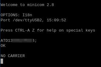
Make a phone call:
Execute AT command:
ATD13xxxxxxxxx; //The phone number to be dialed, note that it must end with a ";"
Wait a moment for the call to connect successfully. When minicom display "OK", the other party will start ringing. There will be no prompt when they answer. After the call ends, hanging up will be indicated by "NO CARRIER":
The following demonstrates a process of dialing, ringing, answering, and hanging up:
Answer the phone call:
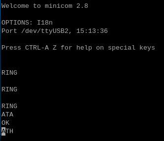
If there is an incoming call, "RING" will be displayed in minicom as the ring alert, and then the following AT commands can be used for control:
ATA //Answer the phone call
ATH //Hanging up the phone call
The following demonstrates a process of ringing, answering, and hanging up:
4.4.4 GPS test
To use the GPS on the EC20, you need to connect an active GPS antenna and ensure that the GPS antenna is extended outdoors. The GPS is operated via AT commands.
Open ttyUSB3 serial port by minicom:
sudo minicom -D /dev/ttyUSB3
and execute:
AT+QGPS=1
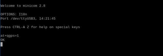
Open ttyUSB1 serial port by minicom, and you can obtain GPS information:
sudo minicom -D /dev/ttyUSB1
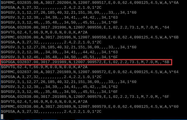
If you find the raw GPS data in minicom not very intuitive, we can install gpsd to extract the GPS information:
sudo apt-get install gpsd gpsd-clients

Then configure the gpsd software:
sudo gpsd /dev/ttyUSB1 -N -D 9 -F /var/run/gpsd.sock -S 3333

Note: 3333 is the listening port, which can be customized as needed.
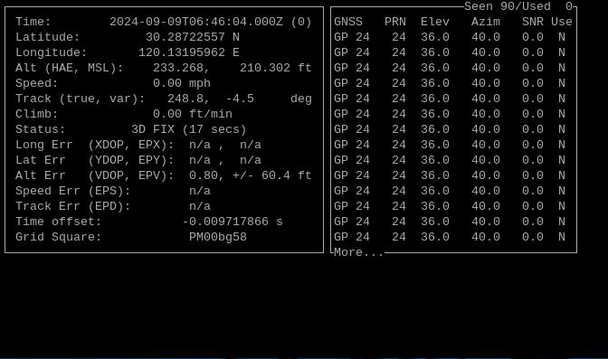
Do not close the configuration terminal window, instead, open a new terminal window and execute:
cgps -s localhost:3333

From the output interface, information such as time, latitude and longitude, speed, and altitude can be seen.
V. Work with Ubuntu OS
5.1 Module connection
The 4G module is automatically recognized in the Ubuntu OS, driver-free and dial-up-free, and is automatically identified as a device starting with "enx...".
5.1.1 Qualcomm 4G and CAT4 4G
After the system starts, by executing ifconfig -a in the terminal, we can see that the 4G module (network interface starting with enx...) has successfully obtained an IP address:

We can ping external network addresses, such as: ping www.mcuzone.com
Connect to the external network via a 4G module and access a speed test website to measure the speed, with the results as follows:
CAT4 4G:
Qualcomm 4G:
Note: Network speed tests are affected by the network environment and testing methods. Please refer to the actual speed, as this test is for reference only.
The status of Status LED:
Qualcomm 4G:
If the LED is blinking slowly with occasional rapid flashes in between, it indicates that the 4G module has connected to the network. Otherwise, it suggests there might be an issue with the SIM card or the network; please check the SIM card and the antenna.
CAT4 4G:
The blinking pattern, where the light is on for 1.8 seconds and off for 0.2 seconds (alternatively, you can judge by the light being on longer than it is off), indicates that the 4G module has connected to the network.
The blinking pattern, where the light is off for 1.8 seconds and on for 0.2 seconds, indicates that there is an issue with the SIM card or the network. Please check the SIM card and the antenna.
5.1.2 ZTE CAT4 4G
After the system starts, by executing ifconfig -a in the terminal:
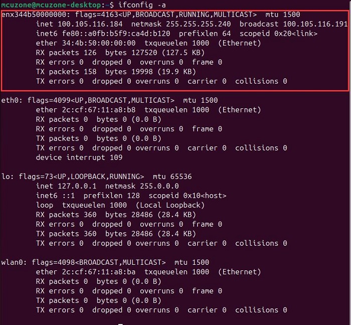
We can see that the system has identified the 4G module (the network card that starts with enx..., in this case enx344b50000000, please verify against actual conditions), and it has correctly acquired an IP address.
We can ping external network addresses, such as: ping www.mcuzone.com
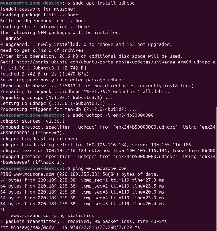
If the server name cannot be found, please install udhcpc:
sudo apt install udhcpc
Please execute the following after successful installation:
sudo udhcpc -i enx344b50000000
then ping:
 .
.
Connect to the external network via a 4G module and access a speed test website to measure the speed, with the results as follows:
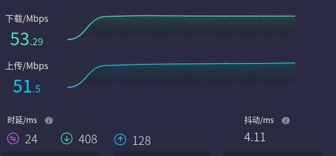
Note: Network speed tests are affected by the network environment and testing methods. Please refer to the actual speed, as this test is for reference only.
The status of Status LED:
If the LED is rapid flashes, it indicates that the 4G module has connected to the network. Otherwise, it suggests there might be an issue with the SIM card or the network; please check the SIM card and the antenna.
5.1.3 EC20-GPS voice simplified version
The EC20 module comes pre-configured from the factory. Under the Ubuntu OS, the module is driver-free, does not require dial-up, is automatically recognized, and is identified as a device starting with "enx...".
After the system starts, running ifconfig -a in the terminal shows that the 4G module has obtained an IP address.
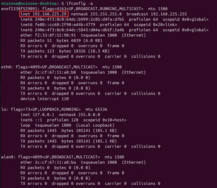
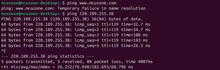
At this point, pinging the URL returns an error, but pinging the IP address is successful, indicating that the 4G module can access the internet normally, but there is an issue with the DNS server settings:
Plug an Ethernet cable into the Gigabit Ethernet port of the Raspberry Pi 5 to connect to the internet via cable. Then install the DNS server switching software udhcpc:
sudo apt install udhcpc
After installation is complete, unplug the network cable and execute:
sudo udcpc -i enxf2338f529091
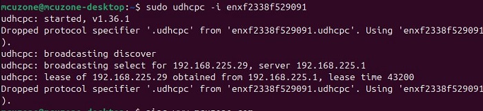
Then you can ping the URL:

Now it is possible to access the internet normally via the 4G network, but each time the OS reboots, it is necessary to run udcpc once. If you want to automatically connect to the 4G network upon startup, you need to add a startup command in the rc.local file. You can refer to the following steps:
Enable rc-local service:
sudo systemctl enable --now rc-local
Open the rc.local file using the following command:
sudo nano /etc/rc.local
Add the commands you want to execute on startup above "exit 0":
sleep 5 && sudo udhcpc -i enxf2338f529091 && sleep 5 && sudo enxf2338f529091 -i usb0 && sleep 5 && sudo enxf2338f529091 -i usb0
The purpose of the sleep command is to delay the execution of subsequent commands by a specified number of seconds. Since it takes some time for the 4G module to obtain an IP address, to prevent udhcpc from failing, it is necessary to execute the command multiple times with a certain delay between each execution. As a result, the 4G network will be available approximately 20 seconds after the system starts up.
Then save the file, so that the OS can automatically connect to the internet via the 4G module upon startup.
The operation steps for sending SMS, making phone calls, and using GPS functions with the EC20 module are consistent with those on the Raspberry Pi OS. Please refer to the relevant content in the previous chapter.
6.1 AT command operation
The usage of AT commands is the same in both Raspberry Pi OS and Ubuntu OS. Here, the operations are demonstrated using the Raspberry Pi OS as an example.
Taking Qualcomm 4G as an example, execute lsusb in terminal:
Record the ID value of the 4G module: 05c6 90b6
Use the following command to open the ttyUSB serial port, where the value after echo is the ID recorded above:
sudo modprobe option
sudo sh -c 'echo 05c6 90b6 > /sys/bus/usb-serial/drivers/option1/new_id'

After execution is complete, the system should have three additional devices: ttyUSB0 - ttyUSB2, execute ls /dev to view:
Then, use a serial port tool to operate AT commands. There are two types of serial port tools, and you can choose one to use:
1. Open the AT command serial port through minicom:
sudo minicom -D /dev/ttyUSB1
2. Or execute the following command to open CuteCom:
sudo cutecom
Select the correct serial port in CuteCom and open it, or open minicom. Note: Which serial port to use should be determined by the ability to enter and execute AT commands without garbled or erratic output after accessing that serial port.
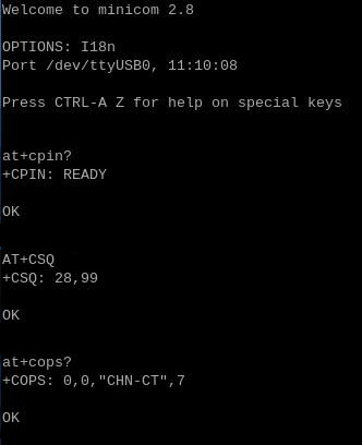
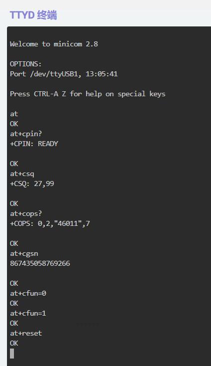
Below is an example using minicom:
If you need to view the echo, please type the command ate1, then execute other commands.
Use AT+CPIN? to check if the SIM card is properly inserted and recognized.
Use AT+CSQ to check the signal strength. The first value ranges from 0 to 31, and a value above 25 indicates good signal quality.
Use AT+COPS? to check the status of the registered network. The content within the double quotes is the operator code, and the last digit represents the network mode, where 7 stands for 4G.
6.2 Modify the IP address of the 4G module
If the default 4G IP address assigned at the factory conflicts with the IP address being used by the user, or if there is a need to modify the IP address, you can change the 4G module's IP.
1. Qualcomm 4G, ZTE CAT4 4G:
Set the 4G module's IP to directly obtain a public IP. Please execute the AT command:
Set the IP to public: AT+GTIPPASS=1
Set the IP to private: AT+GTIPPASS=0
Check whether the current IP is a public or private IP: AT+GTIPPASS?
After modifying the IP, a power cycle reboot is required for the changes to take effect.
2. CAT4 4G:
Execute the AT command:
AT+ROUTEIP=<newip>
Note: only addresses in the format of 192.168.x.1 are supported. If you set AT+ROUTEIP=192.168.3.1, the final IP address obtained will be 192.168.3.100. After making the changes, you need to power off and restart the OS.
Query current IP: AT+ROUTEIP?, it returns two values, the first one is the old IP, and the second one is the new IP.
Test command: AT+ROUTEIP=?
3. We are not know how to modify the IP address of EC20, If needed, users are required to research it themselves.
VII. Work with OpenWrt
This section uses a CAT4 4G module as an example to explain the operation of a 4G module under the OpenWrt.
7.1 Login System
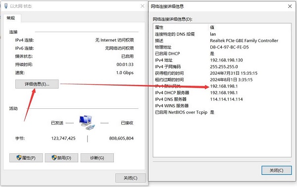
Connect the Ethernet port of the Raspberry Pi 5 to the Ethernet port of the PC. After the system starts up, we navigate to Network & Internet in Windows Settings, open the connected network under Ethernet to view the default gateway's IP address. This address is the backend configuration page address for the OpenWrt. As shown in the figure, the address tested in this article is 192.168.198.1.
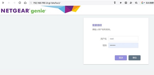
Open a web browser and enter 192.168.198.1 to access the OpenWrt. The default username is root, and the default password is password.
Log in to the "System - TTYD Terminal" and execute ifconfig -a:
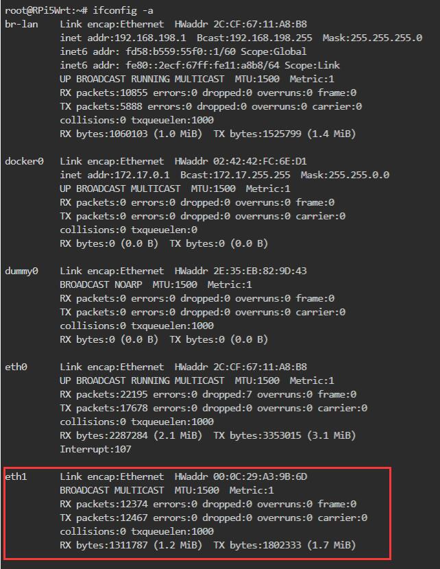
We can see that the system has recognized the 4G module (eth1), but it has not yet obtained an IP address. Next, we will proceed to add the 4G interface.
7.2 Add 4G network
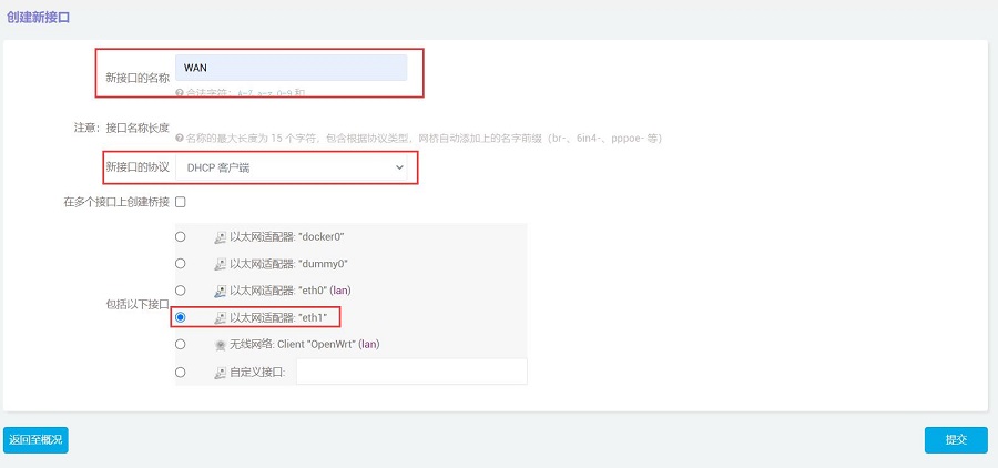
In "Network - Interfaces", click "Add New Interface":
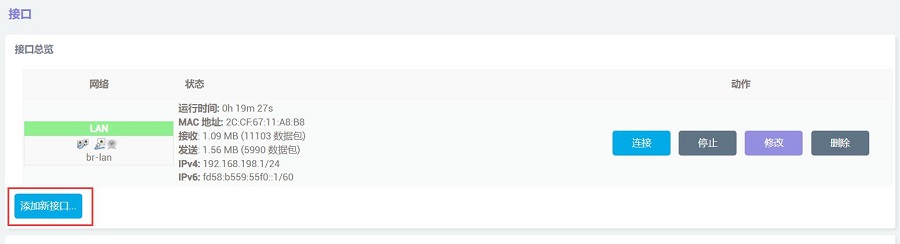
Set the interface name to WAN, select DHCP client for the interface protocol, choose eth1 for the interface, and then click the "Submit" button.
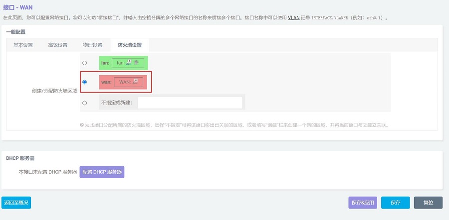
After selecting the WAN port in the firewall settings, click the "Save & Apply" button.
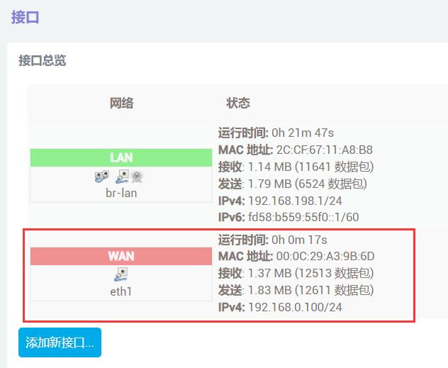
In the "Network - Interfaces" section, we can see that eth1 has already obtained an address as the WAN port.
Return to "System - TTYD Terminal", and after logging in, execute ifconfig -a:
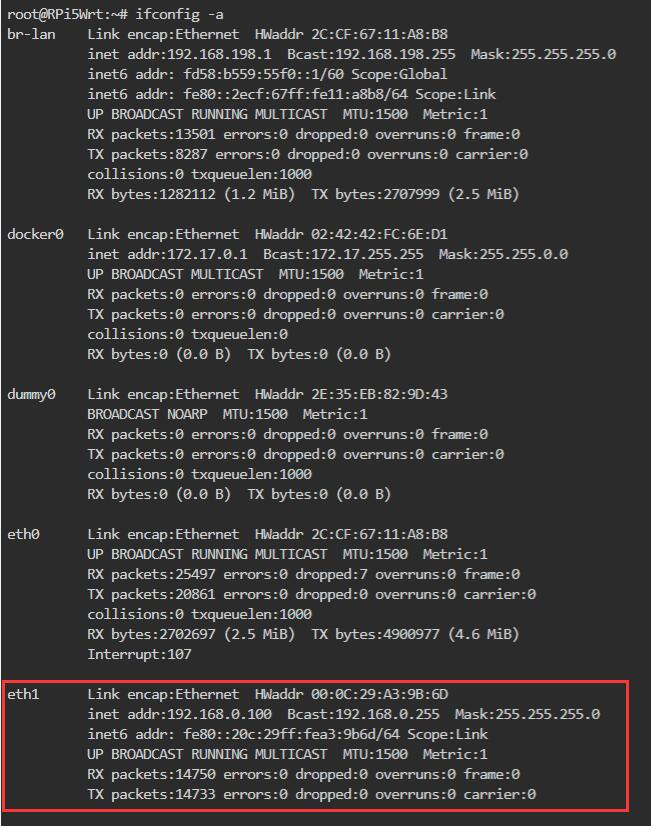
We can see that the 4G module(eth1) has successfully obtained an IP address, and we can ping external network addresses, such as:
ping www.mcuzone.com
The PC can now connect to the external network via the 4G module and access the speed test website. The results are as follows:
Note: Network speed tests are affected by the network environment and testing methods. Please refer to the actual speed, as this test is for reference only.
7.3 AT command operation
If you want to use AT commands on 4G modules, you need to install a serial tool first. If the system does not have a serial tool, it will not be possible to use them. The system demonstrated here already has the minicom installed. The specific steps are as follows:
Log in to the "System - TTYD Terminal" and execute ifconfig -a:
Record the ID value of the 4G module: 1286 4e3d
Use the following command to open the ttyUSB serial port, where the value after echo is the ID recorded above:
modprobe option
sh -c 'echo 1286 4e3d > /sys/bus/usb-serial/drivers/option1/new_id'
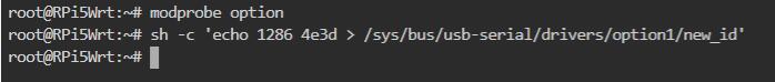
After execution is complete, the system should have 3 additional devices: ttyUSB0 - ttyUSB2, execute ls /dev to view:
Open AT Command serial port by minicom:
minicom -D /dev/ttyUSB1
(Note: Which serial port to use should be determined by the ability to enter and execute AT commands without garbled or erratic output after accessing that serial port.)
If you need to view the echo, please type the command ate1, then execute other commands.
Type the AT command and press Enter to see the result:
VIII.4G application 1 (Remote Connection to Raspberry Pi)
With the Raspberry Pi paired with 4G module and using the official remote control software Raspberry Pi Connect, you can securely access your Raspberry Pi from anywhere in the world.
The configuration and usage instructions are as follows:
1. Apply for a Raspberry Pi ID at https://id.raspberrypi.com/.
2. Install the Raspberry Pi Connect software in the Raspberry Pi OS (no need to install if it is already installed):
sudo apt install rpi-connect
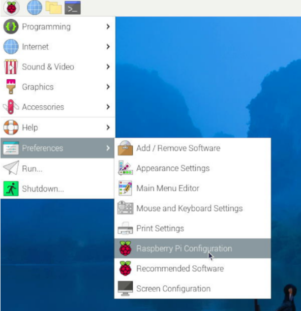
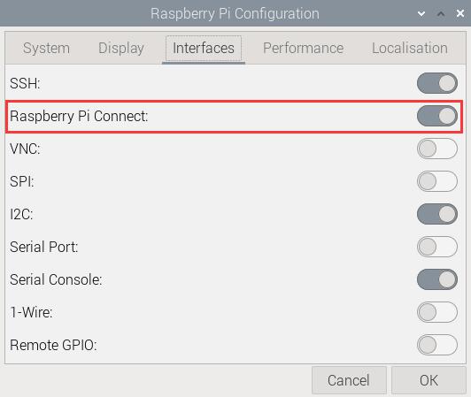
3. Restart the system, and in the GUI, sequentially select the items as shown in the following image to ensure that Raspberry Pi Connect is turned on:
4. In the upper right corner, there will be a Raspberry Pi Connect icon.
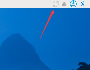
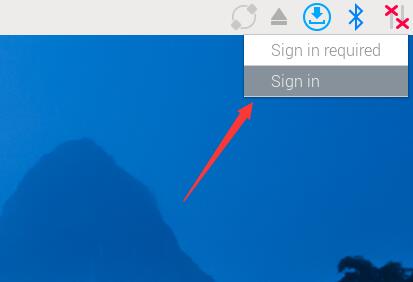
5. Click on this icon, select "Sign in" and use your previously registered Raspberry Pi ID to log in on the pop-up webpage. Then set the device name.
6. After successfully logging in, access https://connect.raspberrypi.com/ in a browser on Windows and log in.
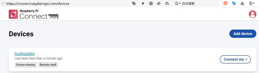
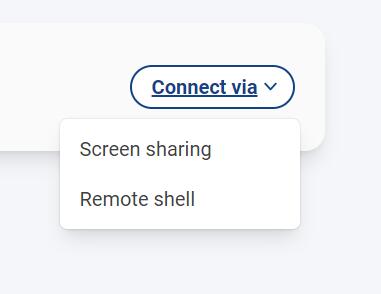
7. Click "Connect via" to choose between using Remote Desktop or the Remote Command Line Interface.
8. Remote desktop is as follows:
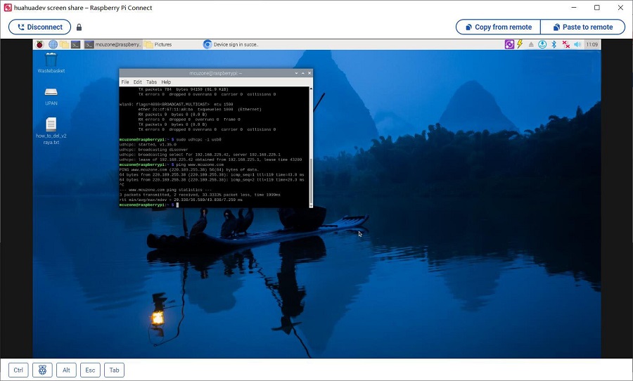
The remote command line interface is as follows:
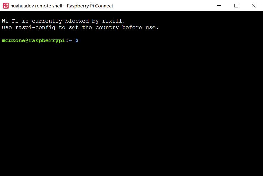
9. Measured data usage: Under remote desktop, the Raspberry Pi consumes about 2MB of data per minute; under remote command line interface, the Raspberry Pi consumes about 100KB of data per minute.
9.1 Raspberry Pi OS
Under the Raspberry Pi OS, we can create a hotspot using the built-in WiFi (such as on the Raspberry Pi 5) and then share the Raspberry Pi's network connection through the hotspot. This chapter introduces how to connect the Raspberry Pi OS to a CAT4 4G network, establish a WiFi hotspot, and allow other devices to use the 4G data connection through this hotspot. The steps are as follows:
9.1.1 Establish a WiFi hotspot
After the Raspberry Pi OS boots up and successfully connects to the 4G network, click the network icon in the upper right corner to open the wireless network options.
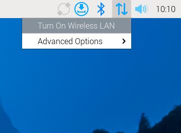
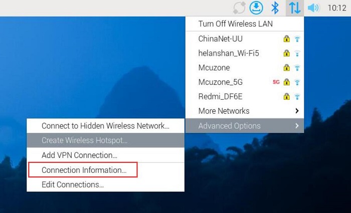
Under "Advanced Options", click "Create Wireless Hotspot..."

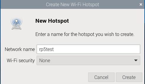
In the pop-up window, enter the network name (SSID) for the hotspot. Enable the wireless encryption options below as needed. After completing the setup, click "Create".
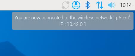
If the creation is successful, the internal IP address of the hotspot will immediately be displayed under the network icon (the fourth icon from the left with up and down arrows in the image below):
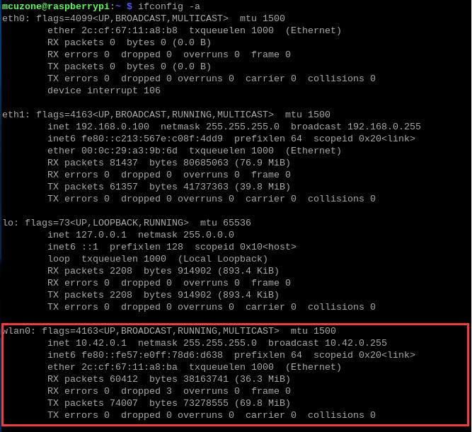
By executing ifconfig -a in the Raspberry Pi terminal, you can view the information of the hotspot (wlan0):
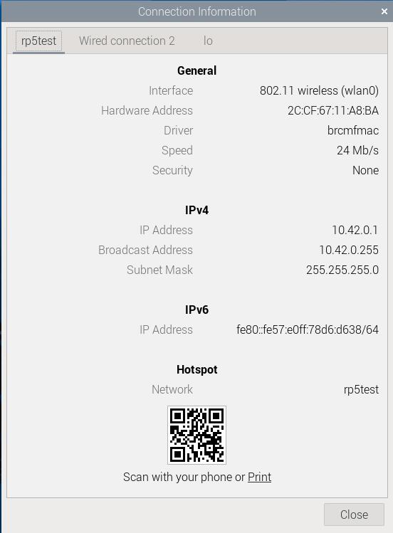
We can also click on the network icon in the upper right corner, then under "Advanced Options" click on "Connection Information..." (highlighted in red) to view the hotspot details.
9.1.2 Application Operation
Connect to this hotspot using your phone:
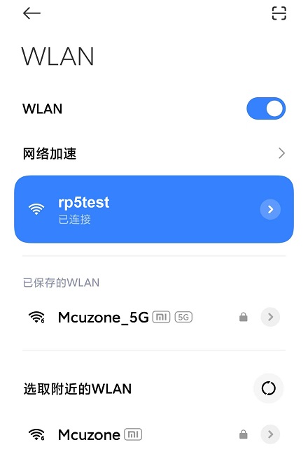
We conducted a speed test on the speed test website, and the results are as follows:
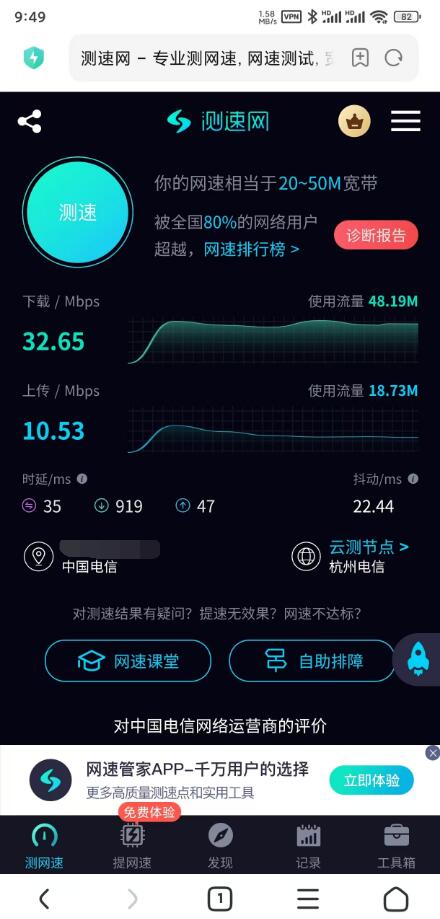
Note: Network speed tests are affected by the network environment and testing methods. Please refer to the actual speed, as this test is for reference only.
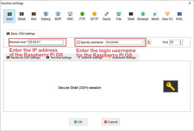
Download and install the terminal software MobaXterm on your PC. The download link for MobaXterm is:
https://mobaxterm.mobatek.net/download-home-edition.html
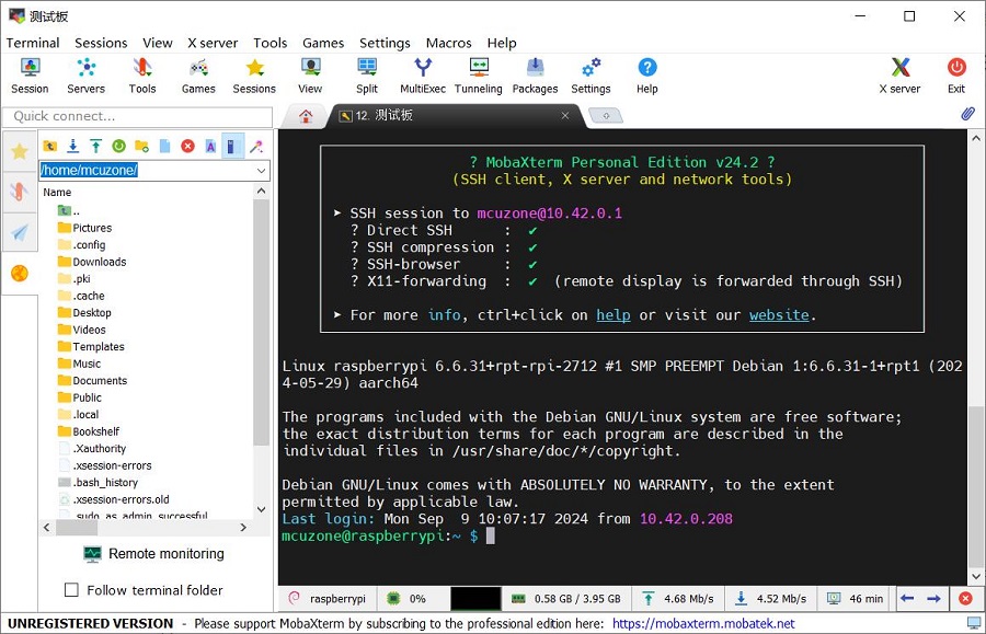
Connect the PC to this hotspot, then use an SSH tool like MobaXterm to successfully connect to the Raspberry Pi OS. This way, you can wirelessly control the development board via the 4G network without the need for an Ethernet cable or other networks, providing great convenience for on-the-go debugging.
9.2 Ubuntu OS
Under the Ubuntu OS, we can create a hotspot using the built-in WiFi (such as on the Raspberry Pi 5) and then share the Raspberry Pi's network connection through the hotspot. The steps are as follows:
9.2.1 Establish a WiFi hotspot
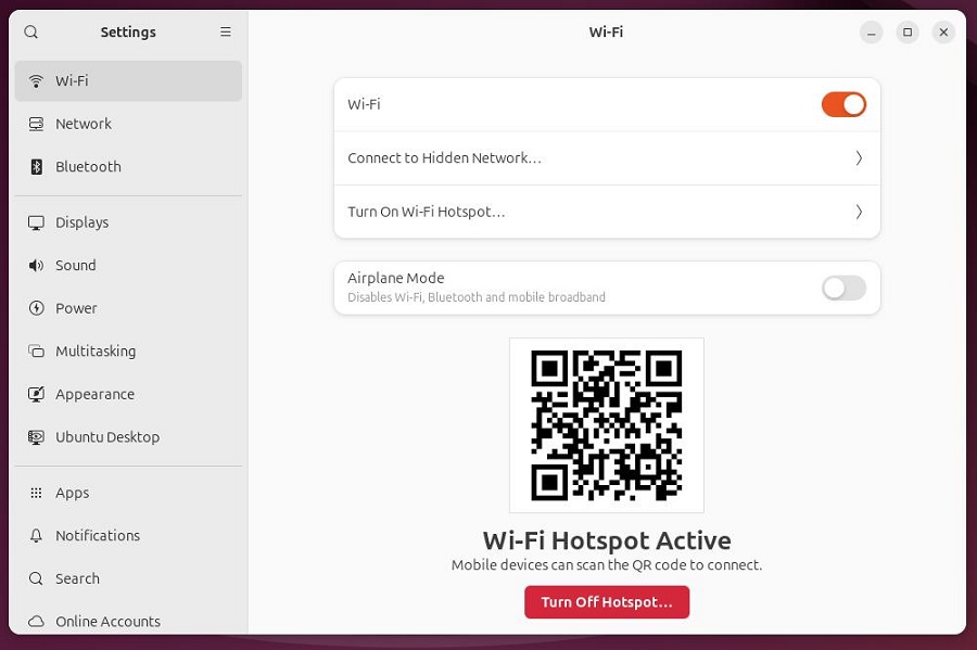
After the Ubuntu OS starts up and successfully connects to the 4G network, click the network icon in the upper right corner, then click the arrow next to "Wi-Fi" to open the wireless network options.
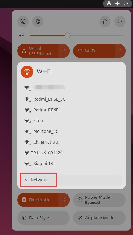
Click "All Networks" to open Wi-Fi settings:
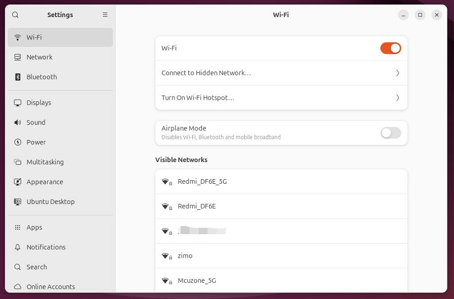
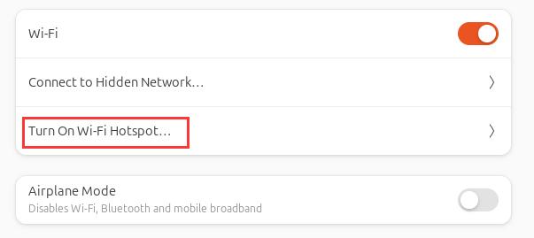
Click "Turn On Wi-Fi Hotspot...", enter the network name (SSID) and password (at least 8 characters) in the pop-up window, then click "Turn On".
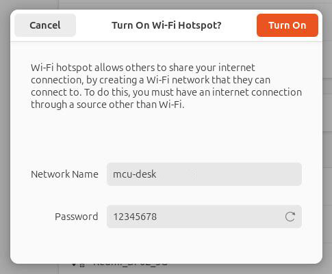
Thus, the hotspot setup is complete.
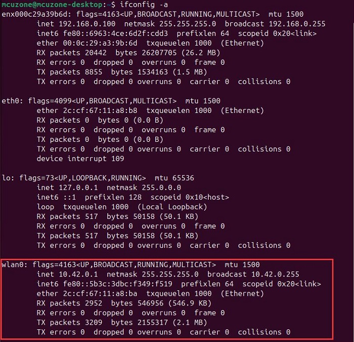
By executing ifconfig -a in the terminal, you can view the information of the hotspot (wlan0):
9.2.2 Application Operation
Connect to this hotspot using your phone:

We conducted a speed test on the speed test website, and the results are as follows:
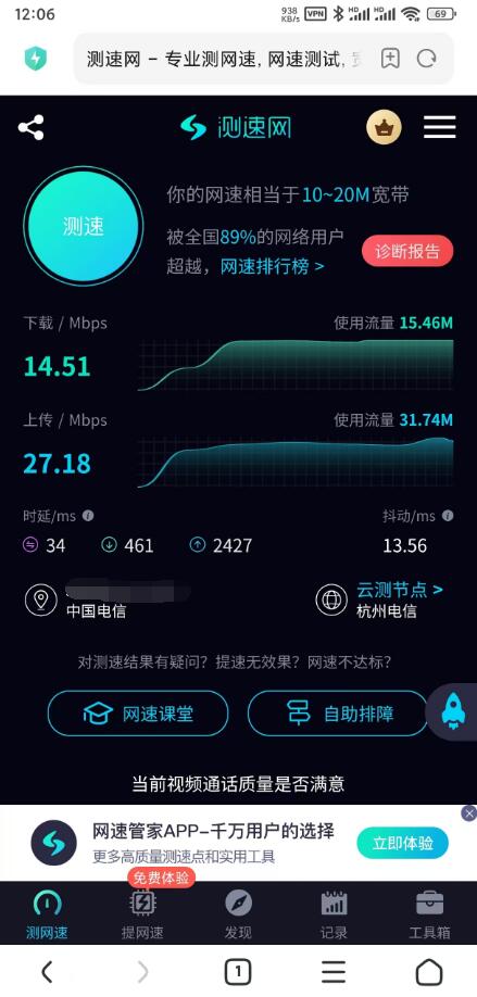
Note: Network speed tests are affected by the network environment and testing methods. Please refer to the actual speed, as this test is for reference only.
X. Points to note
1. Since 2024, the new version of Raspberry Pi OS may assign the default internet device to a specific one during startup when multiple internet devices are present. This is the reason why we mentioned the need to use udhcpc to specify a new default internet device in the previous context. This causes significant inconvenience for applications that need to go online immediately after booting. So we can write the udhcpc command into the rc.local file to automatically assign a default network device at startup.
2. Regarding how to add startup commands in the rc.local file, you can refer to the following steps (using the Qualcomm 4G module as an example, where usb0 represents the 4G module, and the name should be based on the actual situation):
Enable rc-local service:
sudo systemctl enable --now rc-local
Open the rc.local file using the following command:
sudo nano /etc/rc.local
Add the commands you want to execute on startup above "exit 0":
sleep 5 && sudo udhcpc -i usb0 && sleep 5 && sudo udhcpc -i usb0 && sleep 5 && sudo udhcpc -i usb0
The purpose of the sleep command is to delay the execution of subsequent commands by a specified number of seconds. Since it takes some time for the 4G module to obtain an IP address, to prevent udhcpc from failing, it is necessary to execute the command multiple times with a certain delay between each execution. As a result, the 4G network will be available approximately 20 seconds after the system starts up.
Then save the file, so that the OS can automatically connect to the internet via the 4G module upon startup.
3. In summary, we can configure the system to enable 4G internet access upon startup, and then set up Raspberry Pi Connect (which is set to start automatically by default). This way, after the device boots up, it will only take a short wait before it can be remotely controlled from a PC.
Contact Us


 QQ:8204136
Email: mcuzone@vip.qq.com
Tel: +86(0)13957118045
If there are any omissions, errors, or infringements on this page, please contact us through the above methods. Thank you!
Copyright 2004-2025 Wildchip