0002 MPS2280-PoE(SSD expansion board with PoE Ethernet Power Supply)
Keywords:
2280, PoE, LCD screen
Ⅰ、Introduction
The MPS2280iPoE is a PoE-powered SSD expansion board designed for the Raspberry Pi 5, featuring voltage and current monitoring functions. It supports SSDs in sizes 2230, 2242, and 2280. The system can boot from the SSD, or from a TF card with the SSD used only for storage.
Ⅱ、System flashing and configuration
1. Boot from a TF card
At this time, the SSD is used for storage purposes only. Use the Raspberry Pi Imager to write the image, select the Raspberry Pi 5 device, and use the image 2024-07-04-raspios-bookworm-arm64.img.xz (Raspberry Pi OS) or ubuntu-24.04-preinstalled-desktop-arm64+raspi.img.xz (Ubuntu system) for this document.

balenaEtcher can also be used to flash the image.

2. Boot from the SSD
You need to remove the SSD from the expansion board, insert it into an M.2 (PCIe protocol) to USB card reader, connect it to the PC, and use the same method as flashing an image to a TF card to flash the system image to the SSD. Then remove the SSD, and reinsert it into the expansion board.
Ⅲ、Demonstration of Voltage and Current Monitoring Function(INA219)
1. Open I2C
Method 1: Using the command line.
Input sudo raspi-config in the Raspberry Pi OS's terminal,Select the corresponding options according to the picture below:

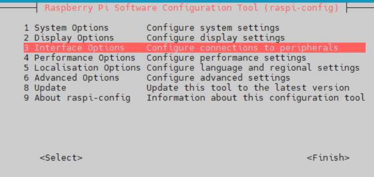
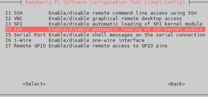
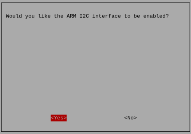
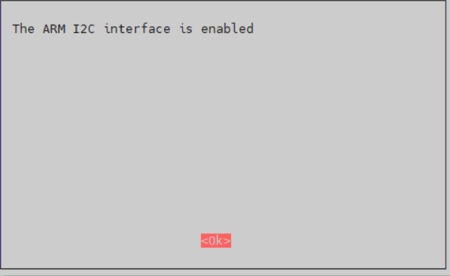
Open the I2C in sequence, then restart the Raspberry Pi.
Method 2: Using the GUI.
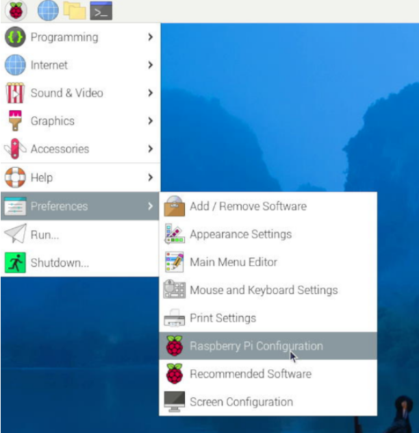
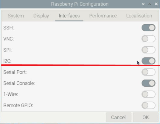
Open the I2C in sequence, then restart the Raspberry Pi.
2. 运行python脚本检测电压电流
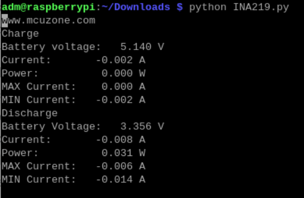
系统重启后,将我司提供的Python脚本(INA219.py)拷贝入树莓派操作系统中,执行该文件(python INA219.py)即可实时检测电压电流。
Python脚本下载地址(需解压):
http://www.mcuzone.com/wiki/0002_MPS2280iPoE/INA219.zip
四、OLED屏的使用演示
1. 树莓派系统下的OLED屏使用演示
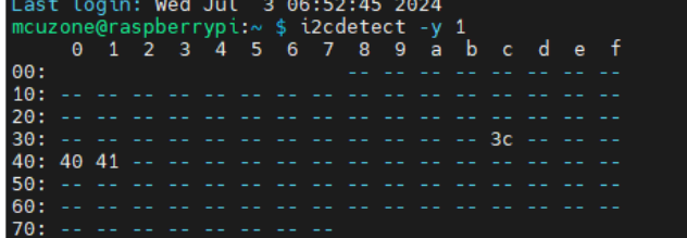
1) 确认树莓派I2C已经打开,且可以看到液晶屏被识别0x3c。
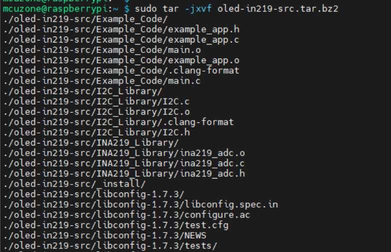
2) 将源码包移入树莓派系统并解压:
sudo tar -jxvf oled-in219-src.tar.bz2
源码包下载地址:
http://www.mcuzone.com/wiki/0002_MPS2280iPoE/oled-in219-src.tar.bz2
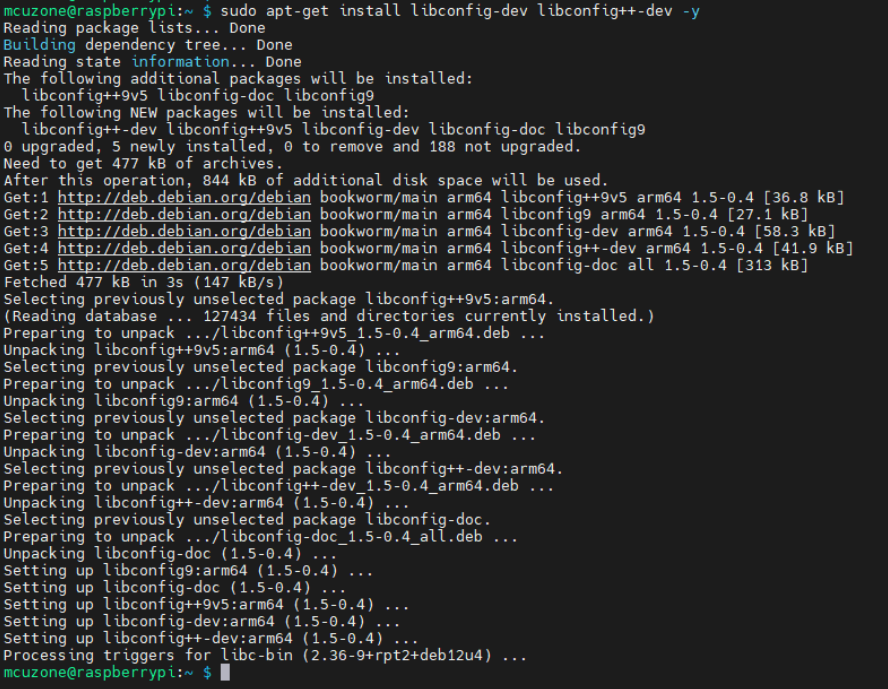
3) 安装依赖:sudo apt-get install libconfig-dev libconfig++-dev -y
4) 进入oled-in219-src目录,依次执行命令sudo make clean、sudo make,编译成功后会生成oled可执行文件。

5) 编译后运行 ./oled -D:
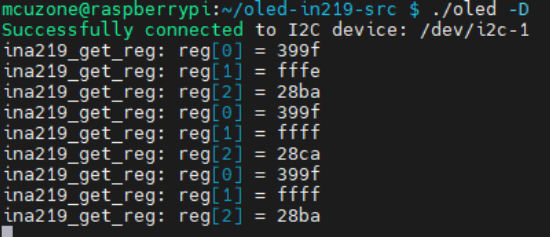
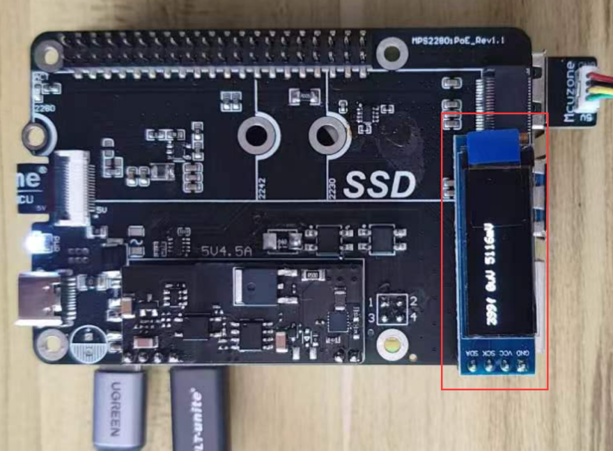
同时在扩展板的OLED屏上也会输出相应的显示。
2. Ubuntu系统下的OLED屏的使用演示
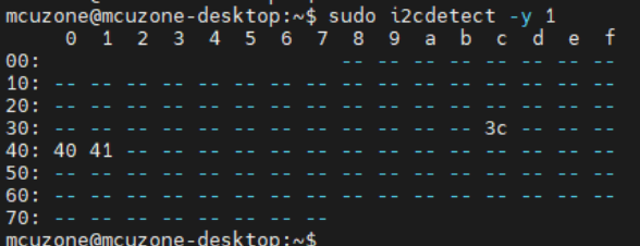
1) 确认树莓派I2C已经打开,且可以看到液晶屏被识别0x3c。
Ubuntu系统需要自己安装I2C工具(sudo apt install i2c-tools)。
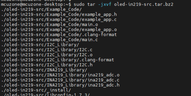
2) 将源码包移入树莓派系统并解压:
sudo tar -jxvf oled-in219-src.tar.bz2
源码包下载地址:
http://www.mcuzone.com/wiki/0002_MPS2280iPoE/oled-in219-src.tar.bz2
3) 安装依赖:sudo apt-get install libconfig-dev libconfig++-dev -y

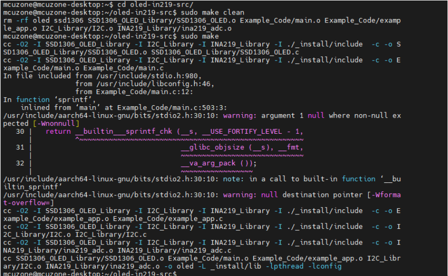
4) 进入oled-in219-src目录,依次执行:
sudo apt install make
sudo apt install gcc
sudo make clean
sudo make
编译成功后会生成oled可执行文件。
编译后运行 ./oled -D:
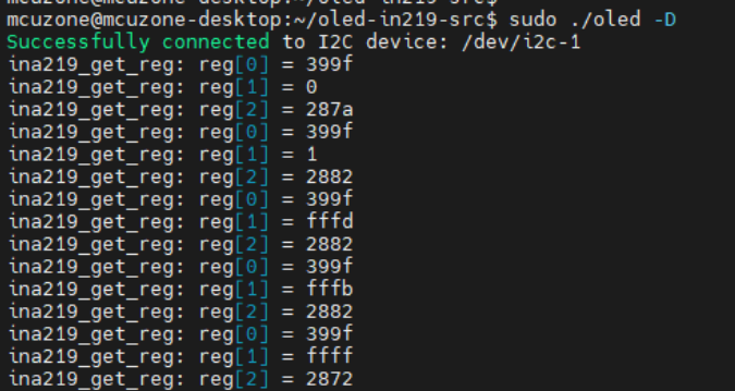
同时在扩展板的OLED屏上也会输出相应的显示。
