3002 21700 5V3A Power Bank
Keywords
Raspberry 4B, Raspberry Pi, 21700 Power Battery, 5V2A, 5V3A, 5V4A, Interactive Serial Port, Serial Port Commands, Charge and Discharge Simultaneously, Real-time Voltage Monitoring
I. Introduction
The 21700 power module is specifically designed for the Raspberry Pi and can supply power to it via pogo pins or a USB port. The board is divided into two areas. On the left side, there is a typical power bank design where charging and discharging share the same port. This means that connecting an external power source will charge the battery, while connecting a device will allow it to be powered externally. The charging capacity can reach up to 2.8A, and the discharging capacity can provide up to 5V2A. The right side of the board features a battery boost circuit with a main power switch. It can supply power to the Raspberry Pi through gold-plated pogo. Additionally, it has two USB-A ports for powering other peripherals. Furthermore, battery information can be viewed via a serial interface. The battery circuit supports simultaneous charging and discharging, and it comes equipped with overcharge protection, overheat protection during charging, as well as overheat protection, overcurrent protection, undervoltage protection, and short-circuit protection during discharging. Practical tests have shown that when connected to a Raspberry Pi 4B playing 1080P video, the battery life can last up to 10 hours using the probe version.
II. Hardware Resources
1. Hardware Features
- Suitable for Raspberry Pi series motherboards, featuring two independently dual output interfaces: one at 5V2A and the other at 5V4A.
- The 5V2A port offers three types of connectors (USB-C, USB-A, micro USB) and supports simultaneous input and output. This means that when 5V is input, it enters charging mode, and when a device is connected, it switches to discharging mode.
- The 5V2A USB-A port supports charging both iPhone and Android devices.
- The 5V4A output provides stable power, functioning as a UPS. It features dual USB high-current ports that share a 4A current and can also supply power via pogo pins.
- One output switch and one output control button are provided to manage the two USB-A ports.
- The board features four LED lights for indicating the battery level.
- A battery level indicator button is provided to check the battery status.
- A power status indicator light.
- The probe version features serial communication pogo pins, while the USB version includes onboard serial communication pins. Both are used for serial communication.
- Two 21700 batteries can be connected in parallel, providing a maximum capacity of 10000mAh. The module can also operate using just one battery.
- Size: 85*56mm; Height: 38.6mm, measured from the bottom acrylic plate to the copper pillars on the board.
- The PCB board uses a gold plating process and is produced without lead. The PCB board has passed UL and ROHS certification, with a fire resistance rating of 94V-0.

2. Product Features
- MCU用于电源管理,并支持串口输出,用于提示电池电压和输出电压;
- 两路MOSFET用于输出控制,支持低电压关闭输出,支持手动或串口命令关闭/打开输出;
- 充电头(输入)检测功能。
3. Serial port output characteristics
- 自动上报电池电压和输出端电压,上位机系统可据此估算系统续航时间并提前做好数据保护。上报间隔可通过命令设置,默认间隔为2秒;
- 自动点亮电量指示LED,方便观察,可通过命令设置点亮间隔,默认为1分钟;
- 可设置电池低电压保护阈值,默认为3V关闭输出;
- 可查询系统上电总时长;
- 可通过命令关闭/打开两路输出;
- 可设置按键用于控制其中一路输出或者两路输出。
- 注意:不支持电流采样。
串口线用于数据传输,连接如下图所示:

4. Battery Description
本产品使用两节21700动力锂电池并联提供电源,可提供长时间续航,可靠放电能力达10A以上,确保5V2A加5V4A足功率双输出。采用开关模式充电,所以即便充电电流达到2.8A,芯片和电池也不会出现过热保护情况。建议采用5V2.5A以上的适配器充电;如果适配器达不到2.5A的输出能力,可能会导致充电时充电头保护(充不进)甚至损坏。
电池极性和安装说明:

21700电池能量巨大,请千万看清楚方向再放入电池座。一旦插反很可能会冒烟起火甚至爆炸,为了大家安全着想,请仔细核对,非必要请勿插拔!
对于因电池接反导致的任何风险我们概不承担,请小心使用;且因电池接反导致的器件损坏不在保修范围内。
因用户自备的电源适配器充电,导致电池炸了或器件损坏,概不保修,请用优质正品电源,或从我司采购。
5. Power indication and output control
可通过电量检测按键查看剩余电量:

可通过输出控制按键控制USB1或者USB2输出:

6. Dual output application
本产品的一个大特点是支持双输出:
一路为5V2A,常开输出;可以同时接3个外部设备,也可以边冲边放,即一进两出;不管同时接2路还是3路,均共享5V2A。
一路为5V4A大功率输出,具备顶针接口和2个USB-A接口;因此,若使用顶针版,此路输出口可同时接3个设备,共享5V4A。
此应用最多可以同时接6个设备;若边冲边放,可同时接5个设备,可支持树莓派、4G模块、舵机、雷达模组等用同一个电源模块同时工作,解决供电问题。

三、串口交互(树莓派OS)
此操作基于树莓派OS版本为:2024-10-22-raspios-bookworm-armhf.img.xz
树莓派OS下载地址:
https://www.raspberrypi.com/software/operating-systems/#raspberry-pi-os-64-bit
3.1 配置树莓派OS
左上角树莓派标志—Preferences—Raspberry Pi Configuration—Interfaces
将Serial Port打开,Serial Console关闭,如图所示:
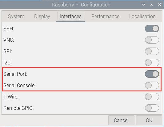
这样就完成了串口配置。
3.2 查看电源实时参数
使用串口命令进行交互,串口软件可以使用minicom或者CuteCom,安装命令如下:
sudo apt install minicom
sudo apt install cutecom
在树莓派OS下,交互串口为ttyS0(注意,S为大写)。
3.2.1 使用minicom软件
打开树莓派终端,运行minicom:
sudo minicom -D /dev/ttyS0
即可看到交互信息:
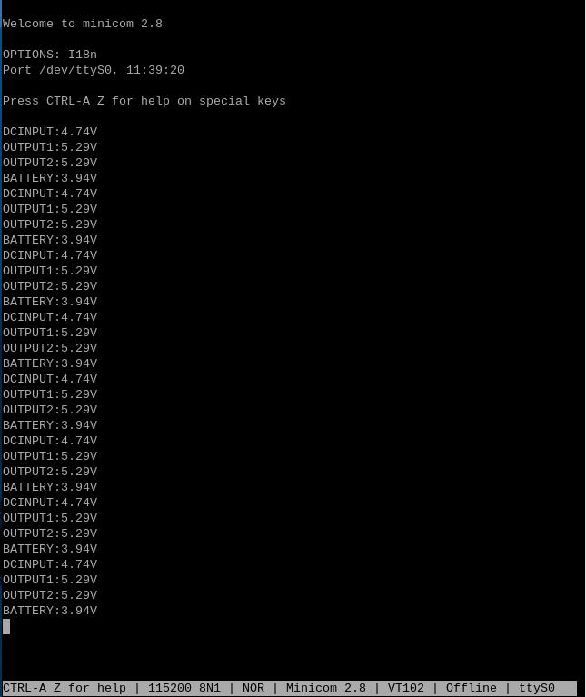
DCINPUT:直流输入电压
OUTPUT1:输出电压1
OUTPUT2:输出电压2
BATTERY:电池电压
3.2.2 使用CuteCom软件
运行CuteCom软件,打开ttyS0串口,在输出窗口中查看交互信息:
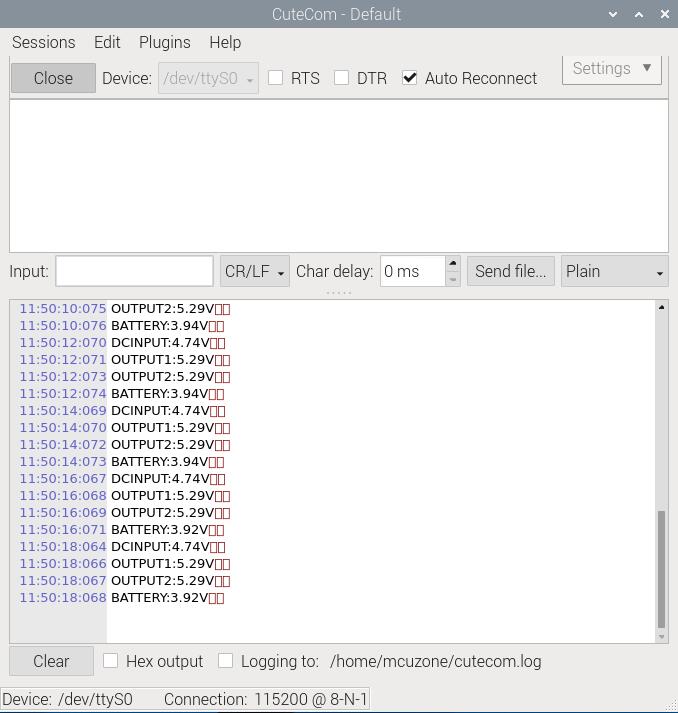
3.3 运行电源系统控制命令
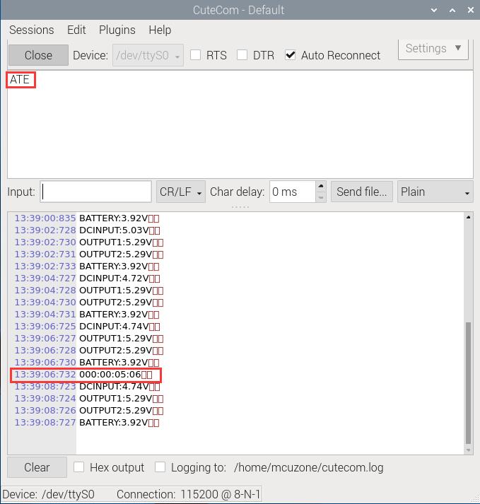
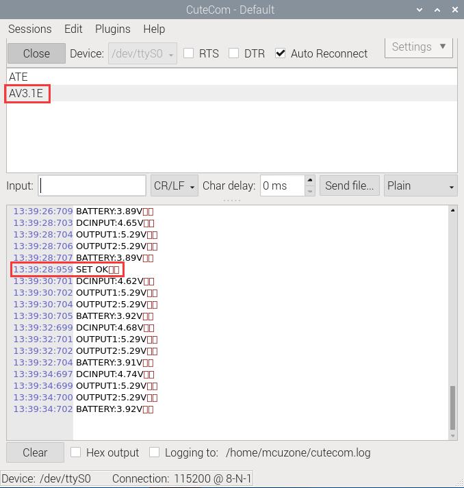
运行CuteCom软件,打开ttyS0串口,在输入(Input)窗口中输入命令,在输出窗口中查看相应的返回信息。
如ATE表示查询系统总运行时长:
AV3.1E表示电池电压低于3.1V时关闭电源输出:
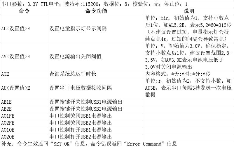
常用控制命令列表:
四、串口交互(Ubuntu系统)
此操作基于Ubuntu系统版本为:ubuntu-24.10-preinstalled-desktop-arm64+raspi.img.xz
Ubuntu系统下载地址:
https://ubuntu.com/download/raspberry-pi
4.1 设置配置
修改Ubuntu系统的配置:
sudo nano /boot/firmware/cmdline.txt

删除红框中的文字,然后保存退出:
console=tty1

sudo nano /boot/firmware/config.txt

添加红框中的文字,然后保存退出:
enable_uart=1
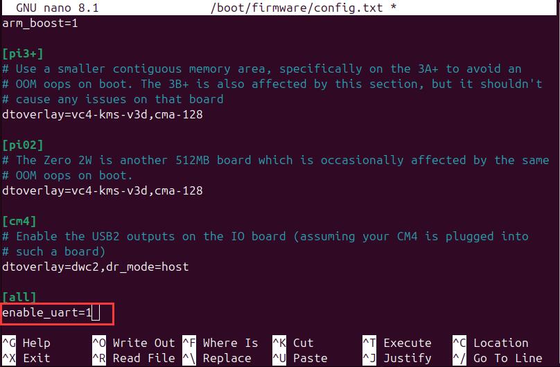
修改完毕后重启系统。
4.2 查看电源实时参数
串口软件可以使用minicom或者CuteCom,安装命令如下:
sudo apt install minicom
sudo apt install cutecom
在Ubuntu系统下,交互串口为ttyS0(注意,S为大写)。
4.2.1 使用minicom软件
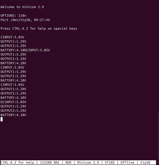
打开Ubuntu系统终端,运行minicom:
sudo minicom -D /dev/ttyS0
即可看到交互信息:
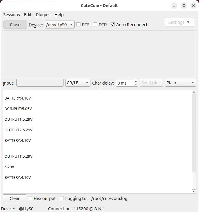
4.2.2 使用CuteCom软件
运行CuteCom软件,打开ttyS0串口,在输出窗口中查看交互信息:
sudo cutecom
五、产品图片


联系我们
电话:13957118045
如本页面有任何疏漏、错误或者侵权,请通过上述途径联系我们,谢谢!
Copyright 2004-2024 野芯科技


 QQ:8204136