1006 RPi0 4G MiniPCIe(Expand 4G Module via MiniPCIe):修订间差异
(创建页面,内容为“== '''关键词''' == 树莓派、 Raspberry Pi Zero、Cat1 4G LTE、USB2.0-A、以太网、扩展板、SSH == '''一、简介''' == Zero系列小巧且预留了非常多的扩展接口,特别是板子反面引出了USB和电源的镀金测试点,我们可以借助这两组USB和电源测试点进行多种类型的外设扩展。本扩展板实际就是一个USB HUB集线器,通过顶针将扩展板和Zero的USB口连接起来,通过USB扩展四路USB…”) |
无编辑摘要 |
||
| 第1行: | 第1行: | ||
== ''' | == '''Keywords''' == | ||
Raspberry Pi, Raspberry Pi Zero, Cat1 4G LTE, USB2.0-A, Ethernet, Expansion Board, SSH | |||
== ''' | == '''I. Introduction''' == | ||
The Zero series is compact and offers many expansion interfaces. The underside of the board features gold-plated test points for USB and power connections. These USB and power test points allow us to connect various types of peripherals for expansion. This expansion board is a USB hub, connecting the expansion board to the USB port of the Zero via pogo pins. It extends four USB ports through the USB connection: one USB port is converted to a 100Mbps wired Ethernet connection, one USB port is connected to a MiniPCIe 4G Cat1 module, and two USB2.0-A host interfaces are provided. | |||
4G | The 4G LTE module is a high-cost-performance module aimed at medium-speed IoT applications, capable of meeting the majority of connectivity and transmission needs. The 4G LTE module supports Qualcomm 4G/GPS, NL668-EU/EAU/AM, GoTone EG25-G. | ||
== ''' | == '''II. Hardware Spec''' == | ||
2.1 | 2.1 Use gold-plated pogo pins to connect the Raspberry Pi Zero series, eliminating the need for external cables; | ||
2.2 | 2.2 The two groups of gold-plated pogo pins are used separately for power supply and USB communication. | ||
2.3 | 2.3 The expansion board is equipped with a USB-C power supply interface, which can power the entire system. The Micro USB port on the Zero can also be used for power. | ||
2.4 | 2.4 The onboard USB hub expands the Zero's USB into four ports: one port is used for connecting a MiniPCIe 4G LTE Cat1 module, one is a USB to 10/100Mbps Ethernet adapter, and two are USB host interfaces. | ||
2.5 4G | 2.5 The 4G LTE module supports Qualcomm 4G/GPS, NL668-EU/EAU/AM, GoTone EG25-G. | ||
2.6 4G | 2.6 The 4G LTE Cat1 module is a plug-and-play in most systems, driver-free and does not require manual dialing, usually recognized as the eth1 network card. | ||
2.7 4G | 2.7 The 4G LTE Cat module uses a Nano-sized SIM card and offers the option of either an SMA antenna or a first-generation IPEX antenna. | ||
2.8 | 2.8 The expansion board supports other Pi with USB contacts in the same position, such as the Orange Pi Zero 2W. | ||
2.9 | 2.9 Onboard PWR/MODE/ACT LED. | ||
2.10 | 2.10 Onboard reset button for 4G module; | ||
2.11 | 2.11 An optional aluminum alloy enclosure is available. | ||
Note 1: After connecting this expansion board, the Micro USB port on the Zero will no longer be usable. | |||
Note 2: In some systems, it is necessary to disable the OTG function and set the USB mode to Host mode. | |||
Note 3: The expansion board supports all versions of the Raspberry Pi Zero, including the Zero, Zero W, Zero WH, and Zero 2W. | |||
http://www.mcuzone.com/wiki/1006_RPi0_4G_MiniPCIe/1006_RPi0_4G_MiniPCIe_25.jpg | http://www.mcuzone.com/wiki/1006_RPi0_4G_MiniPCIe/1006_RPi0_4G_MiniPCIe_25.jpg | ||
http://www.mcuzone.com/wiki/1006_RPi0_4G_MiniPCIe/ | http://www.mcuzone.com/wiki/1006_RPi0_4G_MiniPCIe/1006_RPi0_4G_MiniPCIe_27.jpg | ||
== '''三、系统烧写及设置''' == | == '''三、系统烧写及设置''' == | ||
2024年10月16日 (三) 10:00的版本
Keywords
Raspberry Pi, Raspberry Pi Zero, Cat1 4G LTE, USB2.0-A, Ethernet, Expansion Board, SSH
I. Introduction
The Zero series is compact and offers many expansion interfaces. The underside of the board features gold-plated test points for USB and power connections. These USB and power test points allow us to connect various types of peripherals for expansion. This expansion board is a USB hub, connecting the expansion board to the USB port of the Zero via pogo pins. It extends four USB ports through the USB connection: one USB port is converted to a 100Mbps wired Ethernet connection, one USB port is connected to a MiniPCIe 4G Cat1 module, and two USB2.0-A host interfaces are provided.
The 4G LTE module is a high-cost-performance module aimed at medium-speed IoT applications, capable of meeting the majority of connectivity and transmission needs. The 4G LTE module supports Qualcomm 4G/GPS, NL668-EU/EAU/AM, GoTone EG25-G.
II. Hardware Spec
2.1 Use gold-plated pogo pins to connect the Raspberry Pi Zero series, eliminating the need for external cables;
2.2 The two groups of gold-plated pogo pins are used separately for power supply and USB communication.
2.3 The expansion board is equipped with a USB-C power supply interface, which can power the entire system. The Micro USB port on the Zero can also be used for power.
2.4 The onboard USB hub expands the Zero's USB into four ports: one port is used for connecting a MiniPCIe 4G LTE Cat1 module, one is a USB to 10/100Mbps Ethernet adapter, and two are USB host interfaces.
2.5 The 4G LTE module supports Qualcomm 4G/GPS, NL668-EU/EAU/AM, GoTone EG25-G.
2.6 The 4G LTE Cat1 module is a plug-and-play in most systems, driver-free and does not require manual dialing, usually recognized as the eth1 network card.
2.7 The 4G LTE Cat module uses a Nano-sized SIM card and offers the option of either an SMA antenna or a first-generation IPEX antenna.
2.8 The expansion board supports other Pi with USB contacts in the same position, such as the Orange Pi Zero 2W.
2.9 Onboard PWR/MODE/ACT LED.
2.10 Onboard reset button for 4G module;
2.11 An optional aluminum alloy enclosure is available.
Note 1: After connecting this expansion board, the Micro USB port on the Zero will no longer be usable.
Note 2: In some systems, it is necessary to disable the OTG function and set the USB mode to Host mode.
Note 3: The expansion board supports all versions of the Raspberry Pi Zero, including the Zero, Zero W, Zero WH, and Zero 2W.


三、系统烧写及设置
3.1 概述
本文档采用树莓派OS和OpenWrt系统进行测试。
树莓派OS的版本为2024-07-04-raspios-bookworm-arm64.img.xz,树莓派OS下载地址:
https://www.raspberrypi.com/software/operating-systems/#raspberry-pi-os-64-bit
(若使用树莓派Zero一代系列的板子,只支持32位系统,请注意下载版本。)
OpenWrt系统的版本为:openwrt-bcm27xx-bcm2709-rpi-2-squashfs-sysupgrade-linux-6.1.98-20240723.img.gz
3.2 从TF卡启动
3.2.1 使用树莓派镜像烧录器烧写
首先在Windows端安装树莓派镜像烧录器,下载地址:https://www.raspberrypi.com/software/
安装完毕后将TF卡插入读卡器,读卡器插入PC的USB口,然后打开软件:
Raspberry Pi Device:选择Raspberry Pi Zero 2 W;
请选择需要写入的操作系统:选择Raspberry Pi OS(64-bit),为从树莓派官网下载系统镜像烧写(需联网);选择Use Custom,则需要自行选择硬盘上已经下载的系统镜像(无需联网);
储存卡:选择所需烧入的TF卡(即插在PC的USB接口的卡);

选择完毕后按“NEXT”,建议点击“编辑设置”,将一些参数预设置进烧写软件(比如系统用户名和密码,WiFi连接参数、是否要开启SSH服务等),之后在系统启动时就不必再次设置,便于使用。

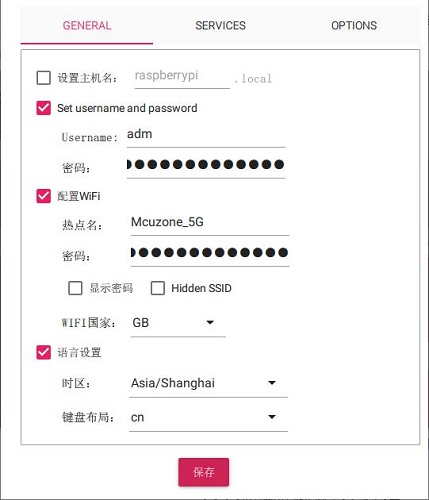
注意:建议把SSH选上,后面要用:
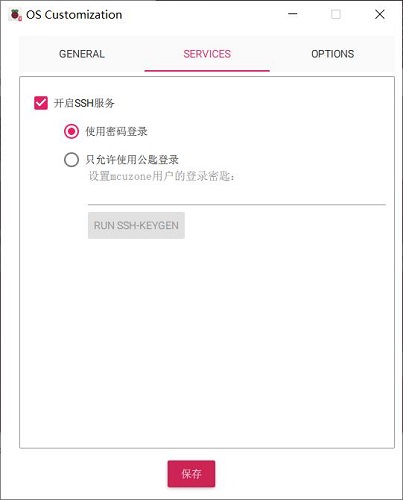
需要使用预设置的按“是”,不需要使用预设置的按“不”,进入下一页,点击“是”,就开始烧写及验证完整性,烧写完毕后按提示取下卡即可。

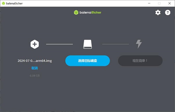
3.2.2 使用balenaEtcher烧写
首先在Windows端安装balenaEtcher,下载地址:https://etcher.balena.io/#download-etcher
将TF卡插入读卡器,读卡器插入PC的USB口,然后打开软件:
从文件烧录:选择预先下载的树莓派OS或者其它操作系统镜像;
选择目标磁盘:选择所需烧入的TF卡(即插在PC的USB接口的卡);
然后点击“现在烧录!”,就开始烧录了,等待烧录完毕即可。
3.2.3 启动系统
将TF卡从读卡器中取下,塞进Zero核心板的TF卡卡槽,上电后即可进入系统。
四、树莓派系统下使用演示
4.1 查看硬件设备
4.1.1 查看USB设备
打开树莓派OS的终端,输入命令lsusb,如下图所示:

Device 002:外挂USB Hub;
Device 003:USB转百兆网卡;
Device 004:USB2.0-A接口;
Device 005:4G模组;
Device 006:USB2.0-A接口;
如果系统卡在树莓派logo处无法启动:
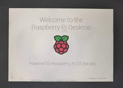
或者启动后键盘鼠标及4G模组都无法使用,请仔细观察顶针是否对准了镀金触点,并请在PC端打开TF卡系统分区根目录下的config.txt检查USB的初始化脚本:
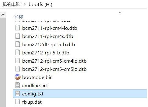
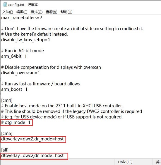
需要确认下图中的三处红框的位置是否都配置成完全,如果没有,请手动添加完整并保存文件:
# otg_mode=1(建议按此注释掉)
dtoverlay=dwc2,dr_mode=host(两处必须确保加上)
4.1.2 查看网络设备
打开树莓派OS的终端,输入命令ifconfig -a,如下图所示:

可以看到eth0为USB转以太网,usb0为4G Cat4模组(上图中IP地址为10.17.34.16),wlan0为无线网卡(已连接,IP地址为192.168.8.71)
4.2 通过SSH连接系统
为了操作方便,建议使用PC端的SSH软件连接系统并进行终端操作,我们使用与树莓派的无线网卡的IP地址在同一网段内的PC,通过MobaXterm进行连接:

连接后,大部分操作都可以通过PC端的MobaXterm进行,使得整套硬件系统可以脱离显示器运作。以下测试操作将通过MobaXterm在PC端进行演示。
4.3 测试网络设备
4.3.1 ping包测试
测试的时候有优先级,如有内外网特殊优先级需要请调整各网络的metric值以及DNS服务器设置。
现在系统已连接WiFi和4G,可以用-I参数指定从哪个网卡开始ping包,如下所示:
ping www.mcuzone.com -I wlan0
ping www.mcuzone.com -I usb0

优先级可以通过可以执行route命令来查看,哪个网卡的metric值小就从优先从哪个网卡通讯。

我们也可以通过关闭某个网卡,达到强制指定通过另一个网络进行通讯,如需关闭usb0,可执行下面的命令:
sudo ifconfig usb0 down
以及通过执行下面的命令来开启usb0:
sudo ifconfig usb0 up
4.3.2 网卡优先级相关设置
有关网卡优先级的相关设置,请参阅以下链接:
4.3.3 iperf3测速
Windows版iperf3下载:
http://www.mcuzone.com/down/Software.asp?ID=10000634
Linux下iperf3安装:
sudo apt-get install iperf3
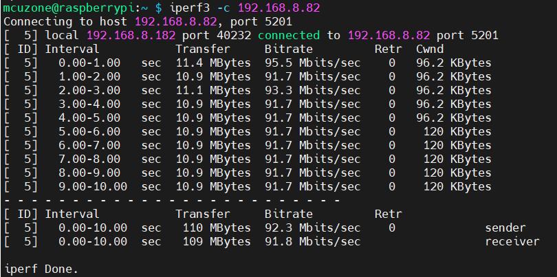
百兆以太网测速结果:
client模式92.3Mbps左右:
server模式94.8Mbps左右:
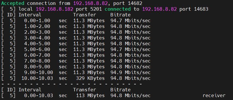
注意:USB转百兆有线受Zero 2W性能和USB Hub以及4G Cat4模组带宽占用影响并不能跑满,请知悉。
4.4 树莓派系统下4G Cat4模组的AT命令演示
4.4.1 打开AT命令串口方法
在树莓派系统下对4G进行AT命令操作,需要打开AT命令串口,打开方法如下:
首先打开ttyUSB串口:
输入命令lsusb,如下图所示:

记下4G模块的ID值:05c6 90b6
使用下列命令打开ttyUSB串口,其中echo后面的值就是上面记录的ID值:
sudo modprobe option
sudo sh -c 'echo 05c6 90b6 > /sys/bus/usb-serial/drivers/option1/new_id'

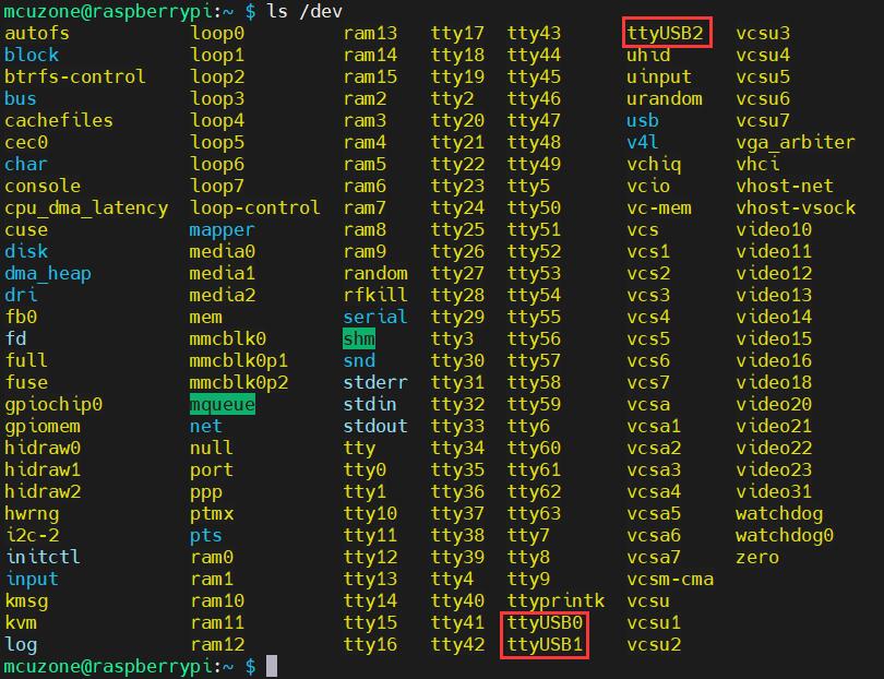
执行以上两条命令后系统应该会多出ttyUSB0-2三个设备,输入ls /dev可以查看:
然后用串口工具打开特定串口:
安装minicom工具:
sudo apt-get install minicom

通过minicom打开AT命令串口:
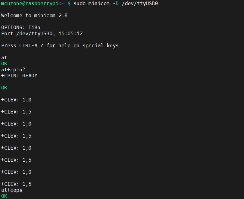
sudo minicom -D /dev/ttyUSB0

然后直接键入AT命令,回车可以看到结果,如果需要查看回显,请键入命令:ate1:
4.4.2 常用AT命令
1) 检查SIM卡是否识别到:
at+cpin?
返回ready表示卡已识别,返回error要检查硬件
2) 检查天线信号质量:
at+csq
返回值在26-31表示信号OK,信号满格31;返回值在20-25表示信号勉勉强强;返回值在20以下表示信号比较糟糕或者天线没接
3) 检查注网情况:
at+cops?
正常应该返回运营商代码和7,7代表4G
注意,以上命令只有at+csq不要加问号,另外两条命令需要加问号。
4) 查看4G模块的IMEI码:
at+cgsn
5) 重启4G模块(有时候如果重插SIM卡,热插拔不一定管用,可以用这个reset命令来复位模块):
at+reset
6) 关闭射频:
at+cfun=0
开启射频:
at+cfun=1
上述两条命令成对使用,可以在不重启4G模组的情况下让模组重新注网。
五、OpenWrt系统操作演示
5.1 概述
此扩展板搭配树莓派Zero 2W,在OpenWrt系统下可配置为一进一出的交换机模式,扩展板上的4G可作为WAN口(直接4G上网),网口配置为LAN口,用于连接PC。
5.2 准备工作
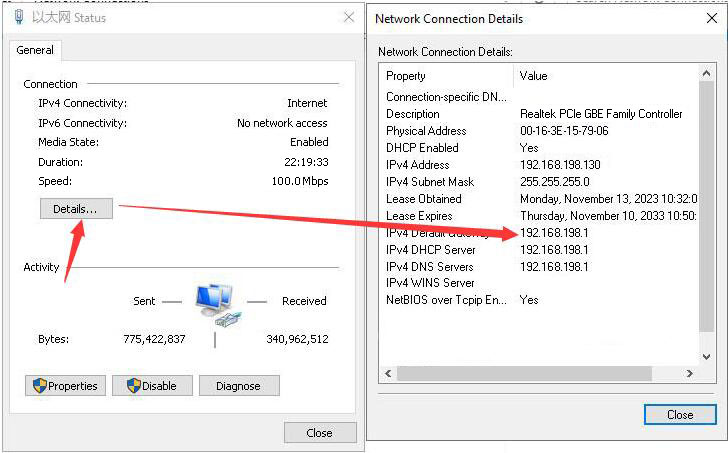
烧写OpenWrt系统并上电启动后,我们通过树莓派自带网口连接网线至PC网口,待PC的网卡与树莓派的网口连接成功后,我们在Windows设置中找到网络和Internet,在以太网中打开连接的网络查看默认网关的IP地址,这个地址就是OpenWrt系统的后台配置页面地址,如图所示,本文测试的地址为192.168.198.1:
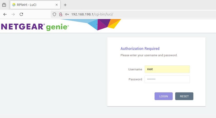
然后打开网页浏览器输入192.168.198.1进入OpenWrt系统。默认用户名为root,默认密码为password:
5.3 设置高通4G LTE模组
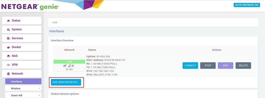
登录OpenWrt系统后,点击“Network - Interface”,然后点击“ADD NEW INTERFACE...”:
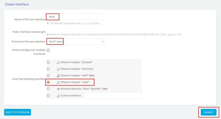
按照下图进行设置,Name of the new interface为WAN,Protocol of the new interface选择DHCP client,Cover the following interface选择usb0,然后点击“SUBMIT”按钮:
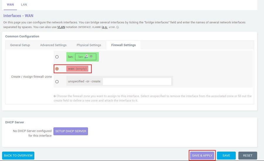
在Firewall Setting中选择WAN口后点击“SAVE & APPLY”按钮:
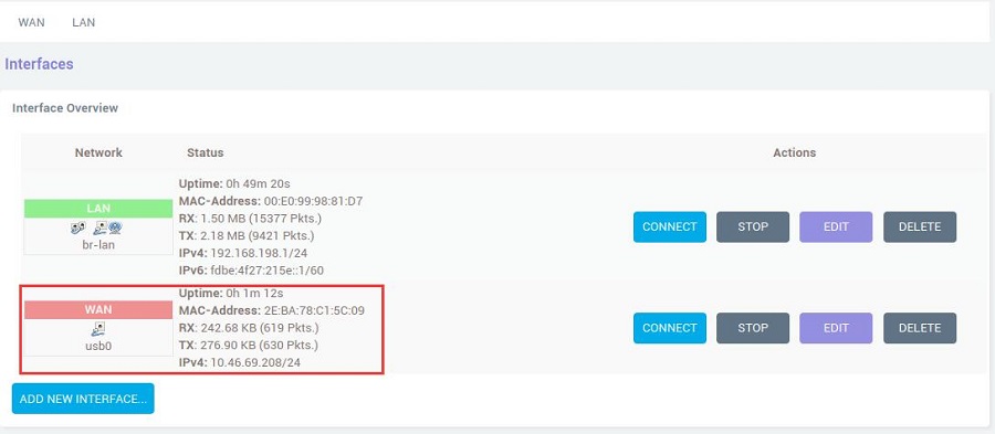
回到“Network - Interface”,稍等片刻,就可以看见新建的WAN接口获取了IP地址,这样PC就可以通过4G LTE模组上网了:
在PC端打开https://www.speedtest.cn/进行测速,此时流量走的是4G模块,测试结果如下:

5.4 设置国产4G CAT4模组
登录OpenWrt系统后,点击“Network - Interface”,然后点击“ADD NEW INTERFACE...”:

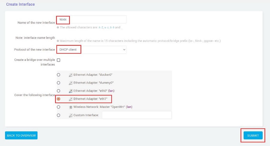
按照下图进行设置,Name of the new interface为WAN,Protocol of the new interface选择DHCP client,Cover the following interface选择eth1,然后点击“SUBMIT”按钮:
在Firewall Setting中选择WAN口后点击“SAVE & APPLY”按钮:

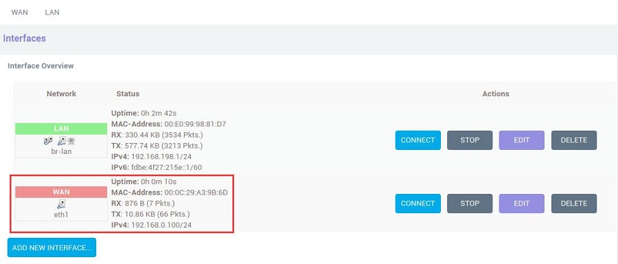
回到“Network - Interface”,稍等片刻,就可以看见新建的WAN接口获取了IP地址,这样PC就可以通过4G LTE模组上网了:
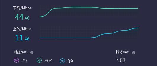
在PC端打开https://www.speedtest.cn/进行测速,此时流量走的是4G模块,测试结果如下:
联系我们
电话:13957118045
如本页面有任何疏漏、错误或者侵权,请通过上述途径联系我们,谢谢!
Copyright 2004-2024 野芯科技


 QQ:8204136