0013 MPSTPU(M.2 E) EN:修订间差异
(创建页面,内容为“== '''关键词''' == 树莓派5、PCIe、TPU、DTPU、驱动安装、操作演示、AI、google、Coral、2230、2242、2280、NVMe SSD、固态硬盘 X1 == '''一、简介''' == Coral M.2加速器是一款M.2尺寸的模组,可以通过PCIE接口为树莓派等平台扩展边缘TPU协处理器。我司的MPSTPU扩展板通过PCIe Switch扩展出了两路PCIe接口,其中一路为M.2 E key接口,可外接A+E Key接口的TPU模组;另一路为M.2 M key…”) |
无编辑摘要 |
||
| 第1行: | 第1行: | ||
== ''' | == '''Keywords''' == | ||
Raspberry Pi 5, PCIe, TPU, DTPU, Driver installation, Operation demonstration, AI, google, Coral, 2230, 2242, 2280, NVMe SSD, SSD X1 | |||
== ''' | == '''I. Introduction''' == | ||
Coral M. | The Coral M.2 Accelerator is an M.2 sized module that can expand edge TPU coprocessing capabilities via the PCIE interface for platforms such as the Raspberry Pi. Our MPSTPU expansion board adds two PCIe interfaces via a PCIe Switch, One is an M.2 E key interface, which can be used to connect a TPU module with an A+E Key interface, the other is an M.2 M key interface, which can be used to connect an NVMe SSD. The MPSTPU expansion board can provide the system with massive SSD storage while adding TPU edge computing capabilities. | ||
== ''' | == '''II. Hardware Resources''' == | ||
1. | 1. Designed for the Raspberry Pi 5, it uses a 16-pin FPC to connect to the Raspberry Pi 5's PCIe interface. | ||
2. | 2. The MPSTPU expansion board adds two PCIe interfaces via a PCIe Switch. | ||
3. | 3. One PCIe extension M.2 E key interface, used for connecting the Google Coral Edge TPU, with the official Raspberry Pi OS loading the driver. | ||
4. | 4. One PCIe expanded M.2 M key slot, for connecting NVMe SSD (PCIe X1, Gen2 mode only). Supports 2230/2242/2280 size SSDs (defaulting to welded mounting posts for 2280 size). | ||
5. | 5. The SSD can be used for data storage and system booting. When booting from the SSD, the Raspberry Pi official firmware needs to be version 2024.5.13 or later. | ||
6. | 6. The 40-pin GPIO section adopts an unobstructed design on the top. It can be connected via DuPont cable, without affecting the use of the Raspberry Pi 5's own GPIO pins. | ||
7. | 7. Gold immersion PCB process, lead-free production, certified by UL, compliant with ROHS standards, and has a fire rating of 94V-0. | ||
http://www.mcuzone.com/wiki/0013_MPTPU_M/0013_MPTPU_M_03.jpg | http://www.mcuzone.com/wiki/0013_MPTPU_M/0013_MPTPU_M_03.jpg | ||
Note: | |||
1. | 1. After the Raspberry Pi 5 firmware update, the settings cannot be modified, or else the firmware will automatically revert to the old version. | ||
2. | 2. Due to the limitations of the switch, PCIe only supports X1 Gen2, with SSD speeds of approximately 400 MB/s. | ||
== ''' | == '''III. System flashing and setting''' == | ||
=== 3.1 概述 === | === 3.1 概述 === | ||
This document uses the Raspberry Pi OS, Ubuntu system and OpenWrt system for testing. | |||
The version of the Raspberry Pi OS is: 2024-07-04-raspios-bookworm-arm64.img.xz | |||
You can download the Raspberry Pi OS in: | |||
https://www.raspberrypi.com/software/operating-systems/#raspberry-pi-os-64-bit | https://www.raspberrypi.com/software/operating-systems/#raspberry-pi-os-64-bit | ||
The version of the Ubuntu system is: ubuntu-24.04-preinstalled-desktop-arm64+raspi.img.xz | |||
You can download the Ubuntu system in: | |||
https://ubuntu.com/download/raspberry-pi | https://ubuntu.com/download/raspberry-pi | ||
The version of the OpenWrt system is: openwrt-bcm27xx-bcm2712-rpi-5-squashfs-sysupgrade-linux-6.1.100-20240805.img.gz | |||
openwrt-bcm27xx-bcm2712-rpi-5-squashfs-sysupgrade-linux-6.1.100-20240805.img.gz | |||
=== 3.2 | === 3.2 System flashed onto the SD (TF) card === | ||
[[0005 MPS2242 | [[0005 MPS2242 2280(Single SSD Expansion Board)#3.2 Boot from TF card|Click here to read the instructions for System flashing]] | ||
=== 3.3 | === 3.3 System flashed onto the SSD === | ||
[[0005 MPS2242 | [[0005 MPS2242 2280(Single SSD Expansion Board)#3.3 Boot from SSD|Click here to read the instructions for System flashing]] | ||
== ''' | == '''IV. Run the TPU module''' == | ||
This chapter introduces how to run the TPU module on Raspberry Pi OS. | |||
The steps in this chapter apply to both systems booting from TF card and from SSD. | |||
=== 4.1 | === 4.1 Config config.txt === | ||
After the system boots, open the Raspberry Pi terminal and enter the command: | |||
<code>sudo nano /boot/firmware/config.txt</code> | <code>sudo nano /boot/firmware/config.txt</code> | ||
Or: | |||
<code>sudo mousepad /boot/firmware/config.txt</code> | <code>sudo mousepad /boot/firmware/config.txt</code> | ||
Add the codes in the ending of this file: | |||
<code>dtparam=pciex1</code> | <code>dtparam=pciex1</code> | ||
| 第77行: | 第79行: | ||
http://www.mcuzone.com/wiki/0006_MPW7_TPU/0006_MPW7_TPU_02.jpg | http://www.mcuzone.com/wiki/0006_MPW7_TPU/0006_MPW7_TPU_02.jpg | ||
Then, save the file and reboot the system: | |||
<code>sudo reboot</code> | <code>sudo reboot</code> | ||
=== 4.2 | === 4.2 Ensuring software environment === | ||
After reboot the system, open the Raspberry Pi terminal and enter the command: | |||
<code>uname -r</code> | <code>uname -r</code> | ||
After ensuring the kernel version is greater than 4.18, enter: | |||
<code>lsmod | grep apex</code> | <code>lsmod | grep apex</code> | ||
Ensure there is no output, then you can begin installing the TPU driver.http://www.mcuzone.com/wiki/0006_MPW7_TPU/0006_MPW7_TPU_03.jpg | |||
http://www.mcuzone.com/wiki/0006_MPW7_TPU/0006_MPW7_TPU_03.jpg | |||
=== 4.3 | === 4.3 Install necessary software === | ||
Ensure the network is connected to internet connection to the regions out of China (you may need to find your own method), and then add the Google TPU software library: | |||
<code>echo "deb <nowiki>https://packages.cloud.google.com/apt</nowiki> coral-edgetpu-stable main" | sudo tee /etc/apt/sources.list.d/coral-edgetpu.list</code> | <code>echo "deb <nowiki>https://packages.cloud.google.com/apt</nowiki> coral-edgetpu-stable main" | sudo tee /etc/apt/sources.list.d/coral-edgetpu.list</code> | ||
| 第103行: | 第103行: | ||
http://www.mcuzone.com/wiki/0006_MPW7_TPU/0006_MPW7_TPU_04.jpg | http://www.mcuzone.com/wiki/0006_MPW7_TPU/0006_MPW7_TPU_04.jpg | ||
Update the software list after adding: | |||
<code>sudo apt-get update</code> | <code>sudo apt-get update</code> | ||
| 第109行: | 第109行: | ||
http://www.mcuzone.com/wiki/0006_MPW7_TPU/0006_MPW7_TPU_06.jpg | http://www.mcuzone.com/wiki/0006_MPW7_TPU/0006_MPW7_TPU_06.jpg | ||
Install the necessary software after the update is completed: | |||
<code>sudo apt-get install cmake libedgetpu1-std devscripts debhelper dkms dh-dkms</code> | <code>sudo apt-get install cmake libedgetpu1-std devscripts debhelper dkms dh-dkms</code> | ||
| 第117行: | 第117行: | ||
http://www.mcuzone.com/wiki/0006_MPW7_TPU/0006_MPW7_TPU_08.jpg | http://www.mcuzone.com/wiki/0006_MPW7_TPU/0006_MPW7_TPU_08.jpg | ||
=== 4.4 | === 4.4 Install Gasket Driver === | ||
Enter the following commands in sequence to install the Gasket Driver: | |||
<code>git clone <nowiki>https://github.com/google/gasket-driver.git</nowiki></code> | <code>git clone <nowiki>https://github.com/google/gasket-driver.git</nowiki></code> | ||
| 第136行: | 第136行: | ||
http://www.mcuzone.com/wiki/0006_MPW7_TPU/0006_MPW7_TPU_11.jpg | http://www.mcuzone.com/wiki/0006_MPW7_TPU/0006_MPW7_TPU_11.jpg | ||
After the installation is complete, enter the following command to ensure that the driver and software were installed successfully: | |||
<code>sudo apt-get install gasket-dkms libedgetpu1-std</code> | <code>sudo apt-get install gasket-dkms libedgetpu1-std</code> | ||
| 第142行: | 第142行: | ||
http://www.mcuzone.com/wiki/0006_MPW7_TPU/0006_MPW7_TPU_12.jpg | http://www.mcuzone.com/wiki/0006_MPW7_TPU/0006_MPW7_TPU_12.jpg | ||
Then, add a udev rule to obtain device operation permissions: | |||
<code>sudo sh -c "echo 'SUBSYSTEM==\"apex\", MODE=\"0660\", GROUP=\"apex\"' >> /etc/udev/rules.d/65-apex.rules"</code> | <code>sudo sh -c "echo 'SUBSYSTEM==\"apex\", MODE=\"0660\", GROUP=\"apex\"' >> /etc/udev/rules.d/65-apex.rules"</code> | ||
add user to apex: | |||
<code>sudo groupadd apex</code> | <code>sudo groupadd apex</code> | ||
| 第154行: | 第154行: | ||
http://www.mcuzone.com/wiki/0006_MPW7_TPU/0006_MPW7_TPU_13.jpg | http://www.mcuzone.com/wiki/0006_MPW7_TPU/0006_MPW7_TPU_13.jpg | ||
Reboot the system after the setup is complete: | |||
<code>sudo reboot</code> | <code>sudo reboot</code> | ||
=== 4.5 | === 4.5 Verification module testing and driver installation === | ||
After system starting, verification module testing and driver installation: | |||
<code>lspci -nn | grep 089a</code> | <code>lspci -nn | grep 089a</code> | ||
Here, you need to see the TPU module, as shown in the following figure (specific parameter display is subject to the actual device): | |||
<code>ls /dev/apex_0</code> | <code>ls /dev/apex_0</code> | ||
| 第169行: | 第169行: | ||
http://www.mcuzone.com/wiki/0006_MPW7_TPU/0006_MPW7_TPU_14.jpg | http://www.mcuzone.com/wiki/0006_MPW7_TPU/0006_MPW7_TPU_14.jpg | ||
This board has a single TPU onboard, so you can see a TPU module: | |||
By entering <code>sudo lspci -v</code>, you can see the driver loading, this must include the TPU driver, and if an SSD is inserted, it also needs to include the SSD module, as shown in the following figure: | |||
http://www.mcuzone.com/wiki/0013_MPTPU_M/0013_MPTPU_M_01.jpg | http://www.mcuzone.com/wiki/0013_MPTPU_M/0013_MPTPU_M_01.jpg | ||
2024年9月2日 (一) 17:37的版本
Keywords
Raspberry Pi 5, PCIe, TPU, DTPU, Driver installation, Operation demonstration, AI, google, Coral, 2230, 2242, 2280, NVMe SSD, SSD X1
I. Introduction
The Coral M.2 Accelerator is an M.2 sized module that can expand edge TPU coprocessing capabilities via the PCIE interface for platforms such as the Raspberry Pi. Our MPSTPU expansion board adds two PCIe interfaces via a PCIe Switch, One is an M.2 E key interface, which can be used to connect a TPU module with an A+E Key interface, the other is an M.2 M key interface, which can be used to connect an NVMe SSD. The MPSTPU expansion board can provide the system with massive SSD storage while adding TPU edge computing capabilities.
II. Hardware Resources
1. Designed for the Raspberry Pi 5, it uses a 16-pin FPC to connect to the Raspberry Pi 5's PCIe interface.
2. The MPSTPU expansion board adds two PCIe interfaces via a PCIe Switch.
3. One PCIe extension M.2 E key interface, used for connecting the Google Coral Edge TPU, with the official Raspberry Pi OS loading the driver.
4. One PCIe expanded M.2 M key slot, for connecting NVMe SSD (PCIe X1, Gen2 mode only). Supports 2230/2242/2280 size SSDs (defaulting to welded mounting posts for 2280 size).
5. The SSD can be used for data storage and system booting. When booting from the SSD, the Raspberry Pi official firmware needs to be version 2024.5.13 or later.
6. The 40-pin GPIO section adopts an unobstructed design on the top. It can be connected via DuPont cable, without affecting the use of the Raspberry Pi 5's own GPIO pins.
7. Gold immersion PCB process, lead-free production, certified by UL, compliant with ROHS standards, and has a fire rating of 94V-0.

Note:
1. After the Raspberry Pi 5 firmware update, the settings cannot be modified, or else the firmware will automatically revert to the old version.
2. Due to the limitations of the switch, PCIe only supports X1 Gen2, with SSD speeds of approximately 400 MB/s.
III. System flashing and setting
3.1 概述
This document uses the Raspberry Pi OS, Ubuntu system and OpenWrt system for testing.
The version of the Raspberry Pi OS is: 2024-07-04-raspios-bookworm-arm64.img.xz
You can download the Raspberry Pi OS in:
https://www.raspberrypi.com/software/operating-systems/#raspberry-pi-os-64-bit
The version of the Ubuntu system is: ubuntu-24.04-preinstalled-desktop-arm64+raspi.img.xz
You can download the Ubuntu system in:
https://ubuntu.com/download/raspberry-pi
The version of the OpenWrt system is: openwrt-bcm27xx-bcm2712-rpi-5-squashfs-sysupgrade-linux-6.1.100-20240805.img.gz
3.2 System flashed onto the SD (TF) card
Click here to read the instructions for System flashing
3.3 System flashed onto the SSD
Click here to read the instructions for System flashing
IV. Run the TPU module
This chapter introduces how to run the TPU module on Raspberry Pi OS.
The steps in this chapter apply to both systems booting from TF card and from SSD.
4.1 Config config.txt
After the system boots, open the Raspberry Pi terminal and enter the command:
sudo nano /boot/firmware/config.txt
Or:
sudo mousepad /boot/firmware/config.txt
Add the codes in the ending of this file:
dtparam=pciex1
kernel=kernel8.img
dtoverlay=pineboards-hat-ai

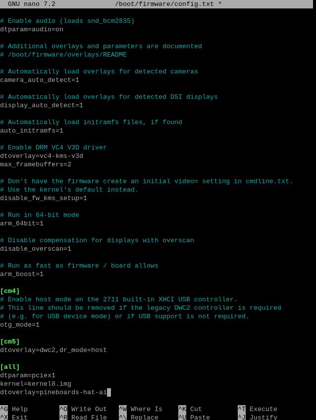
Then, save the file and reboot the system:
sudo reboot
4.2 Ensuring software environment
After reboot the system, open the Raspberry Pi terminal and enter the command:
uname -r
After ensuring the kernel version is greater than 4.18, enter:
lsmod | grep apex
Ensure there is no output, then you can begin installing the TPU driver.
4.3 Install necessary software
Ensure the network is connected to internet connection to the regions out of China (you may need to find your own method), and then add the Google TPU software library:
echo "deb https://packages.cloud.google.com/apt coral-edgetpu-stable main" | sudo tee /etc/apt/sources.list.d/coral-edgetpu.list
curl https://packages.cloud.google.com/apt/doc/apt-key.gpg | sudo apt-key add -

Update the software list after adding:
sudo apt-get update
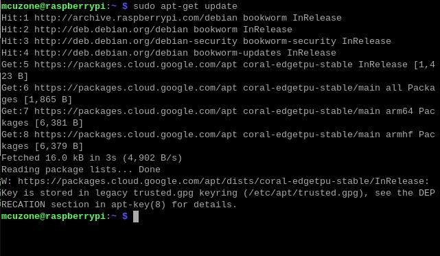
Install the necessary software after the update is completed:
sudo apt-get install cmake libedgetpu1-std devscripts debhelper dkms dh-dkms
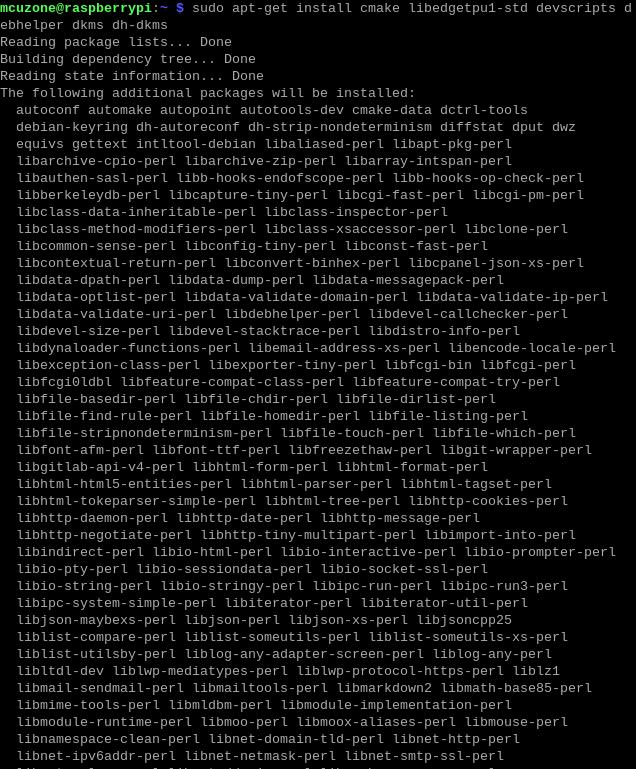

4.4 Install Gasket Driver
Enter the following commands in sequence to install the Gasket Driver:
git clone https://github.com/google/gasket-driver.git
cd gasket-driver
sudo debuild -us -uc -tc -b
cd ..
sudo dpkg -i gasket-dkms_1.0-18_all.deb

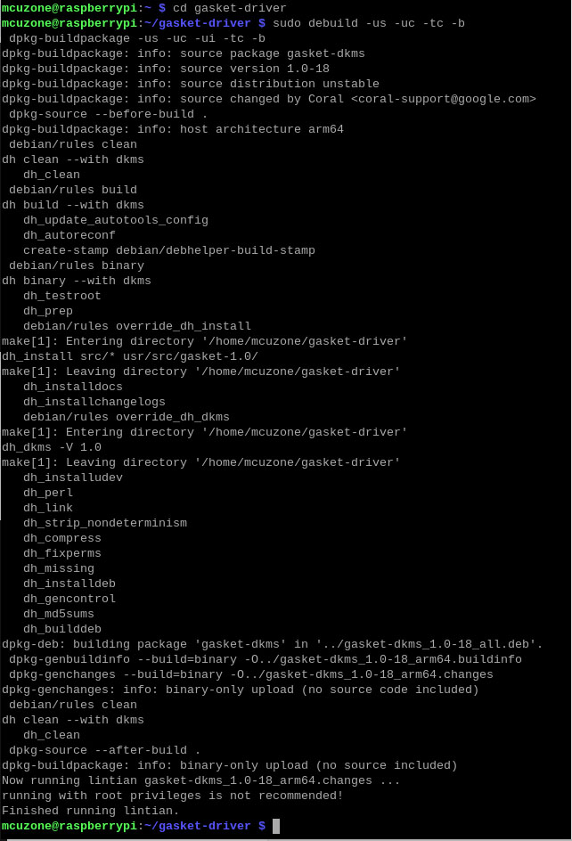
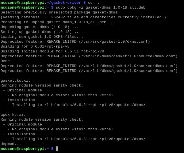
After the installation is complete, enter the following command to ensure that the driver and software were installed successfully:
sudo apt-get install gasket-dkms libedgetpu1-std

Then, add a udev rule to obtain device operation permissions:
sudo sh -c "echo 'SUBSYSTEM==\"apex\", MODE=\"0660\", GROUP=\"apex\"' >> /etc/udev/rules.d/65-apex.rules"
add user to apex:
sudo groupadd apex
sudo adduser $USER apex

Reboot the system after the setup is complete:
sudo reboot
4.5 Verification module testing and driver installation
After system starting, verification module testing and driver installation:
lspci -nn | grep 089a
Here, you need to see the TPU module, as shown in the following figure (specific parameter display is subject to the actual device):
ls /dev/apex_0

This board has a single TPU onboard, so you can see a TPU module:
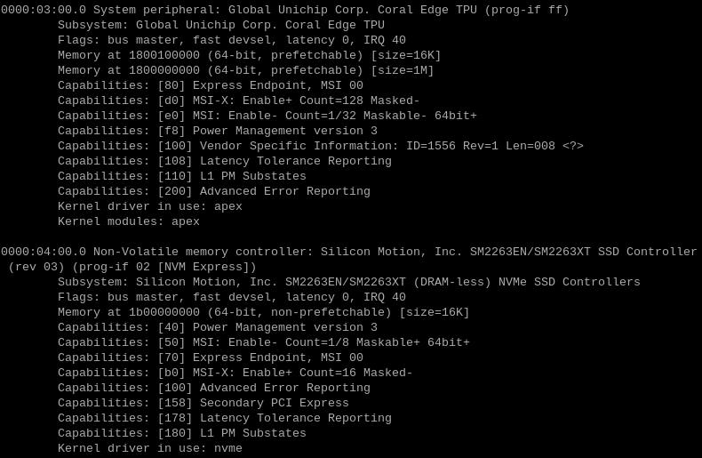
By entering sudo lspci -v, you can see the driver loading, this must include the TPU driver, and if an SSD is inserted, it also needs to include the SSD module, as shown in the following figure:
4.6 代码运行环境配置
Google TPU模块代码运行需要在Python3.6-3.9之间,而树莓派最新系统的Python版本为3.11,因此我们需要使用Pyenv来下载老版本Python。
首先进行依赖安装:
sudo apt-get install -y make build-essential libssl-dev zlib1g-dev \libbz2-dev libreadline-dev libsqlite3-dev wget curl llvm libncurses5-dev \libncursesw5-dev xz-utils tk-dev libffi-dev liblzma-dev python3-openssl

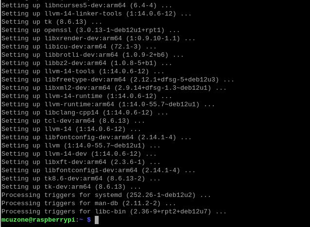
依赖安装完成后进行pyenv的安装:
curl https://pyenv.run | bash

输入:
sudo nano ~/.bashrc
或者:
sudo mousepad ~/.bashrc
在文件最下面添加以下代码:
export PYENV_ROOT="$HOME/.pyenv"
[[ -d $PYENV_ROOT/bin ]] && export PATH="$PYENV_ROOT/bin:$PATH"
eval "$(pyenv init -)"

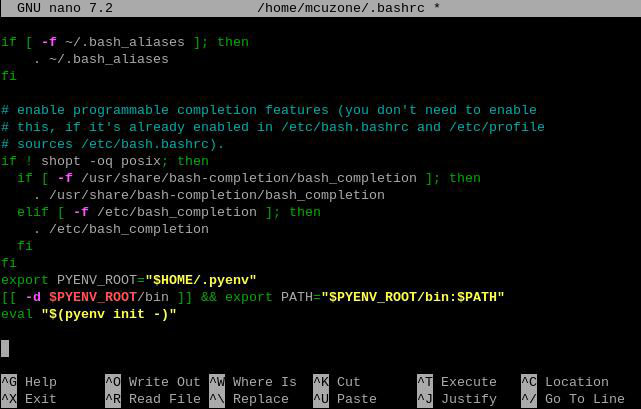
添加完成后保存退出并重新加载shell:
exec "$SHELL"

接下来我们可以利用pyenv安装老系统版本Python:
pyenv install -v 3.8.8


等待安装成功后我们将系统Python版本更改为3.8.8:
pyenv global 3.8.8
更改成功后可以查看当前Python使用版本为3.8.8:
pyenv versions
python3 -V

4.7 下载代码和运行模组
依次输入以下命令进行下载:
mkdir coral && cd coral
git clone https://github.com/google-coral/pycoral.git
cd pycoral
cd test_data
git clone https://github.com/google-coral/test_data.git


接下来下载代码运行模组
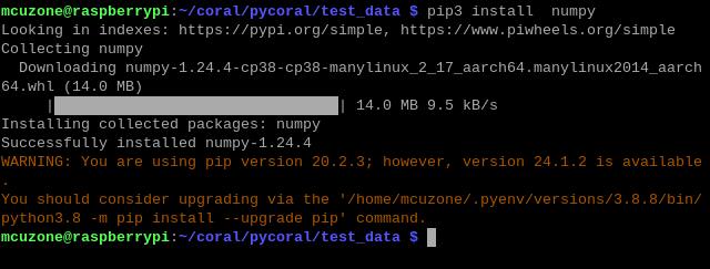
pip3 install numpy
pip3 install Pillow

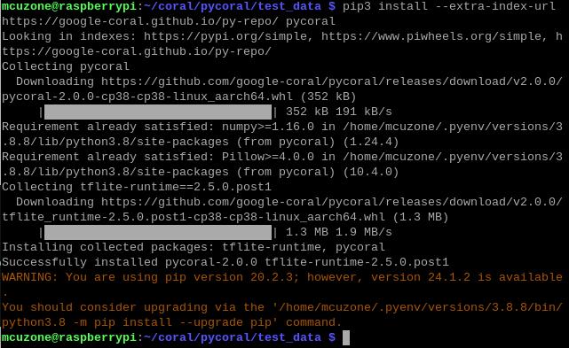
pip3 install --extra-index-url https://google-coral.github.io/py-repo/ pycoral
4.8 运行代码
模组下载完成后返回 coral/pycoral路径下
cd ..
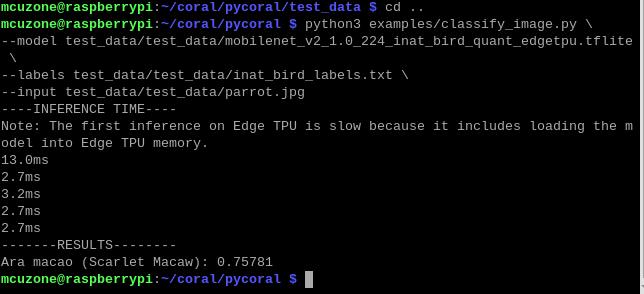
输入以下代码进行代码运行

注意:我们可以复制下列代码,但是请先粘贴到文本软件中,按照上图的格式,删除多余的回车符,再复制然后粘贴到终端中运行:
python3 examples/classify_image.py \
--model test_data/test_data/mobilenet_v2_1.0_224_inat_bird_quant_edgetpu.tflite \
--labels test_data/test_data/inat_bird_labels.txt \
--input test_data/test_data/parrot.jpg
五、树莓派系统下使用SSD硬盘
关于对SSD硬盘的基本操作,我们可以参考以下链接:
关于如何测试SSD硬盘,我们可以参考以下链接:
六、Ubuntu系统下使用SSD硬盘
关于对SSD硬盘的基本操作,我们可以参考以下链接,除了SSD用作存储扩展中与树莓派OS下操作略有不同,其余部分基本相同:
关于如何测试SSD硬盘,我们可以参考以下链接:
七、OpenWrt系统下使用SSD硬盘
关于如何在OpenWrt系统下使用SSD硬盘,我们可以参考以下链接:
联系我们
电话:13957118045
如本页面有任何疏漏、错误或者侵权,请通过上述途径联系我们,谢谢!
Copyright 2004-2024 野芯科技


 QQ:8204136