2003 CM4 Tiny HDMIx2(Dual HDMI Expansion Board):修订间差异
无编辑摘要 |
无编辑摘要 |
||
| 第10行: | 第10行: | ||
== '''Ⅱ、Hardware Resources''' == | == '''Ⅱ、Hardware Resources''' == | ||
1. | 1. One native Gigabit Ethernet port, using an integrated transformer, which provides better electromagnetic performance. | ||
2. | 2. Two standard HDMI ports, supporting 4K output. | ||
3. | 3. One native USB OTG A port (an USB A-A cable can be optionally used to flash system for the eMMC version of the core board via this host port). | ||
4. | 4. One camera CSI interface, 22-pin with 0.5mm pitch, with an optional flexible flat cable adapter from 1mm 15-pin to 0.5mm 22-pin. | ||
5. | 5. The 12-pin GPIO is broken out, containing I2C, UART, and SPI signals, 2.54mm. | ||
6. | 6. One USB-C power supply interface, 5V3A, supporting PD protocol chargers. | ||
http://www.mcuzone.com/wiki/2003_CM4_Tiny_HDMIx2/2003_CM4_Tiny_HDMIx2_35.jpg | http://www.mcuzone.com/wiki/2003_CM4_Tiny_HDMIx2/2003_CM4_Tiny_HDMIx2_35.jpg | ||
== ''' | == '''Ⅲ、System flashing and setting''' == | ||
=== 3.1 | === 3.1 Overview === | ||
This document uses the Raspberry Pi OS and OpenWrt system for testing. | |||
The version of the Raspberry Pi OS is: 2024-07-04-raspios-bookworm-arm64.img.xz | |||
You can download the Raspberry Pi OS in: | |||
https://www.raspberrypi.com/software/operating-systems/#raspberry-pi-os-64-bit | https://www.raspberrypi.com/software/operating-systems/#raspberry-pi-os-64-bit | ||
The version of the OpenWrt is: openwrt-bcm27xx-bcm2711-rpi-4-squashfs-sysupgrade-linux-6.1.100-20240805.img.gz | |||
=== 3.2 Boot from TF card === | |||
If the core board does not have an eMMC, the system will boot from the TF card. | |||
==== 3.2.1 Use the Imager to flash the system ==== | |||
First, install the Imager on the Windows. You can download it in: https://www.raspberrypi.com/software/ | |||
Insert the TF card into the card reader after installation, plug the card reader into the PC's USB port, and then open the software. | |||
Raspberry Pi Device: Choose Raspberry Pi 4; | |||
Operating System: | |||
Raspberry Pi | Choose Raspberry Pi OS(64-bit), to flash the system image downloaded from the Raspberry Pi official website (internet connection required). | ||
Choose Use Custom, to flash the system image already downloaded onto the hard drive (no internet connection required). | |||
Storge: Select the TF card that needs to be flashed (i.e., the card inserted into the PC's USB port). | |||
http://www.mcuzone.com/wiki/0005_MPS2242_2280/0005_MPS2242_2280_01.jpg | http://www.mcuzone.com/wiki/0005_MPS2242_2280/0005_MPS2242_2280_01.jpg | ||
After making your selection, press "NEXT." It is recommended to click "Edit Settings" to pre-set some parameters in the flashing software. This way, you won't need to set them again when the system starts up, making it easier to use. | |||
http://www.mcuzone.com/wiki/0005_MPS2242_2280/0005_MPS2242_2280_02.jpg | http://www.mcuzone.com/wiki/0005_MPS2242_2280/0005_MPS2242_2280_02.jpg | ||
| 第57行: | 第63行: | ||
http://www.mcuzone.com/wiki/0005_MPS2242_2280/0005_MPS2242_2280_03.jpg | http://www.mcuzone.com/wiki/0005_MPS2242_2280/0005_MPS2242_2280_03.jpg | ||
If you need to use the pre-set settings, press "Yes"; if you do not need to use the pre-set settings, press "No". Proceed to the next page, and click "Yes" to start the flashing and verification process. After the flashing is complete, follow the prompts to remove the card. | |||
http://www.mcuzone.com/wiki/0005_MPS2242_2280/0005_MPS2242_2280_04.jpg | http://www.mcuzone.com/wiki/0005_MPS2242_2280/0005_MPS2242_2280_04.jpg | ||
The above instructions describe how to flash the Raspberry Pi OS. For flashing the Ubuntu system or the OpenWrt system, similar operations are used; when you reach the step "Operating System", you need to select Use Custom, and then choose the pre-downloaded image. | |||
==== 3.2.2 | ==== 3.2.2 Use the balenaEtcher to flash the system ==== | ||
First, install the balenaEtcher on the Windows. You can download it in: https://etcher.balena.io/#download-etcher | |||
Insert the TF card into the card reader after installation, plug the card reader into the PC's USB port, and then open the software. | |||
Flash from file: Select the pre-downloaded Raspberry Pi OS or Ubuntu system image. | |||
Select target: Select the TF card that needs to be flashed (i.e., the card inserted into the PC's USB port). | |||
Then click "Flash!" to start the process, and wait for it to complete. | |||
http://www.mcuzone.com/wiki/0005_MPS2242_2280/0005_MPS2242_2280_05.jpg | http://www.mcuzone.com/wiki/0005_MPS2242_2280/0005_MPS2242_2280_05.jpg | ||
==== 3.2.3 | ==== 3.2.3 Boot the system ==== | ||
Remove the TF card from the card reader, insert it into the TF card slot of the Raspberry Pi, and power the board on to enter the system. | |||
=== 3.3. | === 3.3. Boot from eMMC === | ||
If the core board has onboard eMMC, the system will ignore the TF card and boot from the eMMC instead. | |||
To flash the system to the eMMC, you need to install the driver package on the PC first. You can download it in: | |||
http://www.mcuzone.com/down/Software.asp?ID=10000623 | http://www.mcuzone.com/down/Software.asp?ID=10000623 | ||
Then use a jumper cap to short the BOOT pin and the GND pin on the expansion board (located between the two HDMI ports): | |||
http://www.mcuzone.com/wiki/2003_CM4_Tiny_HDMIx2/2003_CM4_Tiny_HDMIx2_34.jpg | http://www.mcuzone.com/wiki/2003_CM4_Tiny_HDMIx2/2003_CM4_Tiny_HDMIx2_34.jpg | ||
Use a '''''USB Type A-A data cable''''' to connect the USB OTG port (i.e., the USB-A port on the expansion board) to the computer. | |||
http://www.mcuzone.com/wiki/2003_CM4_Tiny_HDMIx2/2003_CM4_Tiny_HDMIx2_33.jpg | http://www.mcuzone.com/wiki/2003_CM4_Tiny_HDMIx2/2003_CM4_Tiny_HDMIx2_33.jpg | ||
After connecting to the computer, open the Computer's Device Manager and check if a new USB device appears. In the image below, it is a USB device named "BCM2711 Boot": | |||
http://www.mcuzone.com/wiki/2001_CM4_Ultra/2001_CM4_Ultra_65.jpg | http://www.mcuzone.com/wiki/2001_CM4_Ultra/2001_CM4_Ultra_65.jpg | ||
Under All Programs in the PC's Start menu, there is a shortcut called rpiboot under Raspberry Pi. | |||
http://www.mcuzone.com/wiki/2001_CM4_Ultra/2001_CM4_Ultra_66.jpg | http://www.mcuzone.com/wiki/2001_CM4_Ultra/2001_CM4_Ultra_66.jpg | ||
Open this software, and the computer will format and partition the eMMC or TF card: | |||
http://www.mcuzone.com/wiki/2001_CM4_Ultra/2001_CM4_Ultra_68.jpg | http://www.mcuzone.com/wiki/2001_CM4_Ultra/2001_CM4_Ultra_68.jpg | ||
Wait a moment; a partition will appear in the File Explorer (in this example, the partition is named bootfs, but the actual name may vary): | |||
http://www.mcuzone.com/wiki/2001_CM4_Ultra/2001_CM4_Ultra_67.jpg | http://www.mcuzone.com/wiki/2001_CM4_Ultra/2001_CM4_Ultra_67.jpg | ||
Then, we can use the balenaEtcher software to flash this partition. | |||
打开balenaEtcher软件,第一项点击“从文件烧录”,选择你要烧录到eMMC的文件,第二项选择上面的那个bootfs分区,然后点击“现在烧录”,就开始烧录文件了: | 打开balenaEtcher软件,第一项点击“从文件烧录”,选择你要烧录到eMMC的文件,第二项选择上面的那个bootfs分区,然后点击“现在烧录”,就开始烧录文件了: | ||
2024年8月30日 (五) 16:47的版本
Keywords
Raspberry Pi, CM4 Core board, System Flashing, 4G, RPiOS, eMMC, Dual HDMI, Dual-screen different display
Ⅰ、Introduction
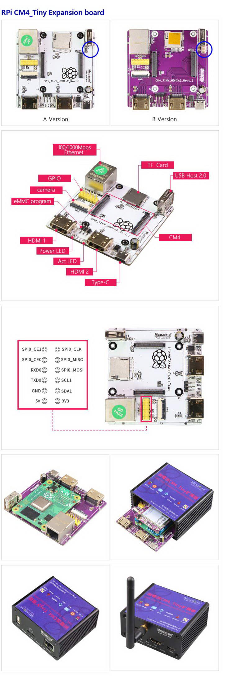
The CM4_Tiny dual HDMI expansion board is designed based on the Raspberry Pi CM4 core board and is a expansion board for applications such as media players, dual-screen different displays, image and video capture, human-computer interaction, remote control, and more.
The CM4_Tiny dual HDMI expansion board has two full-sized HDMI ports, which can be used to output different content to two display devices, and it supports 4K output. It also has native Gigabit Ethernet and a native USB host port, and it includes a reserved 22-pin 0.5mm CAM interface, which can be used to connect various cameras for image and video capture and processing. In addition, there is a 2.54mm pitch 2x6 GPIO header, it is containing I2C, UART, and SPI signals, which can be used for conventional peripheral expansion.
The CM4_Tiny dual HDMI expansion board is powered by a USB-C port at 5V3A.
Ⅱ、Hardware Resources
1. One native Gigabit Ethernet port, using an integrated transformer, which provides better electromagnetic performance.
2. Two standard HDMI ports, supporting 4K output.
3. One native USB OTG A port (an USB A-A cable can be optionally used to flash system for the eMMC version of the core board via this host port).
4. One camera CSI interface, 22-pin with 0.5mm pitch, with an optional flexible flat cable adapter from 1mm 15-pin to 0.5mm 22-pin.
5. The 12-pin GPIO is broken out, containing I2C, UART, and SPI signals, 2.54mm.
6. One USB-C power supply interface, 5V3A, supporting PD protocol chargers.
Ⅲ、System flashing and setting
3.1 Overview
This document uses the Raspberry Pi OS and OpenWrt system for testing.
The version of the Raspberry Pi OS is: 2024-07-04-raspios-bookworm-arm64.img.xz
You can download the Raspberry Pi OS in:
https://www.raspberrypi.com/software/operating-systems/#raspberry-pi-os-64-bit
The version of the OpenWrt is: openwrt-bcm27xx-bcm2711-rpi-4-squashfs-sysupgrade-linux-6.1.100-20240805.img.gz
3.2 Boot from TF card
If the core board does not have an eMMC, the system will boot from the TF card.
3.2.1 Use the Imager to flash the system
First, install the Imager on the Windows. You can download it in: https://www.raspberrypi.com/software/
Insert the TF card into the card reader after installation, plug the card reader into the PC's USB port, and then open the software.
Raspberry Pi Device: Choose Raspberry Pi 4;
Operating System:
Choose Raspberry Pi OS(64-bit), to flash the system image downloaded from the Raspberry Pi official website (internet connection required).
Choose Use Custom, to flash the system image already downloaded onto the hard drive (no internet connection required).
Storge: Select the TF card that needs to be flashed (i.e., the card inserted into the PC's USB port).

After making your selection, press "NEXT." It is recommended to click "Edit Settings" to pre-set some parameters in the flashing software. This way, you won't need to set them again when the system starts up, making it easier to use.

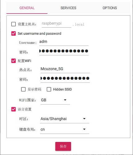
If you need to use the pre-set settings, press "Yes"; if you do not need to use the pre-set settings, press "No". Proceed to the next page, and click "Yes" to start the flashing and verification process. After the flashing is complete, follow the prompts to remove the card.

The above instructions describe how to flash the Raspberry Pi OS. For flashing the Ubuntu system or the OpenWrt system, similar operations are used; when you reach the step "Operating System", you need to select Use Custom, and then choose the pre-downloaded image.
3.2.2 Use the balenaEtcher to flash the system
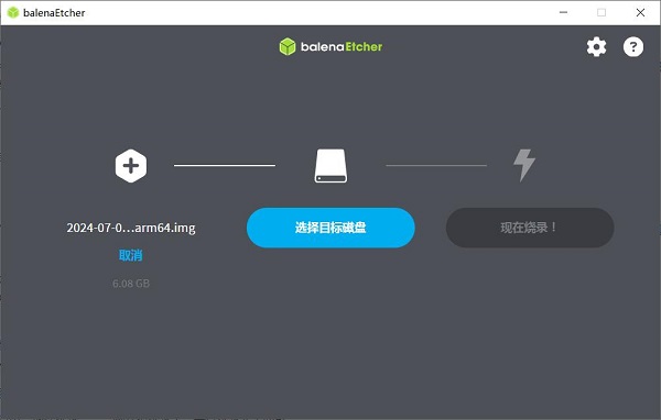
First, install the balenaEtcher on the Windows. You can download it in: https://etcher.balena.io/#download-etcher
Insert the TF card into the card reader after installation, plug the card reader into the PC's USB port, and then open the software.
Flash from file: Select the pre-downloaded Raspberry Pi OS or Ubuntu system image.
Select target: Select the TF card that needs to be flashed (i.e., the card inserted into the PC's USB port).
Then click "Flash!" to start the process, and wait for it to complete.
3.2.3 Boot the system
Remove the TF card from the card reader, insert it into the TF card slot of the Raspberry Pi, and power the board on to enter the system.
3.3. Boot from eMMC
If the core board has onboard eMMC, the system will ignore the TF card and boot from the eMMC instead.
To flash the system to the eMMC, you need to install the driver package on the PC first. You can download it in:
http://www.mcuzone.com/down/Software.asp?ID=10000623
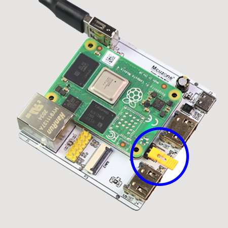
Then use a jumper cap to short the BOOT pin and the GND pin on the expansion board (located between the two HDMI ports):
Use a USB Type A-A data cable to connect the USB OTG port (i.e., the USB-A port on the expansion board) to the computer.
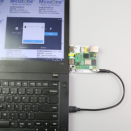
After connecting to the computer, open the Computer's Device Manager and check if a new USB device appears. In the image below, it is a USB device named "BCM2711 Boot":

Under All Programs in the PC's Start menu, there is a shortcut called rpiboot under Raspberry Pi.

Open this software, and the computer will format and partition the eMMC or TF card:

Wait a moment; a partition will appear in the File Explorer (in this example, the partition is named bootfs, but the actual name may vary):

Then, we can use the balenaEtcher software to flash this partition.
打开balenaEtcher软件,第一项点击“从文件烧录”,选择你要烧录到eMMC的文件,第二项选择上面的那个bootfs分区,然后点击“现在烧录”,就开始烧录文件了:


等烧写完成后,我们还要将之前插上的跳线帽拔下来,否则无法正常启动核心板,然后重新给系统上电,待系统启动即可。
四、树莓派OS下的硬件测试
4.1 原生千兆网口测试
我们将网线插入原生千兆网口,系统会自动获取IP,打开终端,安装测速软件iperf3:
sudo apt-get install iperf3
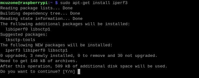
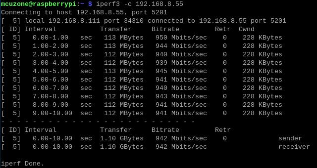
然后我们使用iperf3进行测试:
原生千兆以太网测速结果,client模式为942Mbps左右
server模式为949Mbps左右:
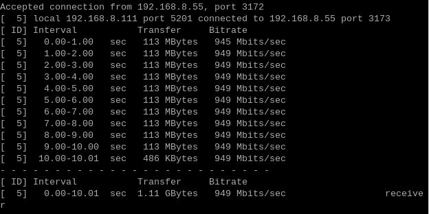
注意:原生千兆网络测速受网络环境和测试方法影响,速度请以实际为准,本测试仅供参考。
4.2 CSI测试
首先将摄像头连接到CAM1接口(在扩展板下方,本文档使用OV5647摄像头):
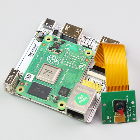
连接好后,给板子上电。等待系统运行后打开终端,运行下列命令:
sudo nano /boot/firmware/config.txt

在文件末尾加入下列语句:
dtoverlay=ov5647,cam0
dtoverlay=ov5647,cam1

在实际使用中根据自己的型号进行添加,保存后重启系统,即可使用OV5647摄像头。
重启后在终端中输入:
ls /dev
即可看到video0设备。
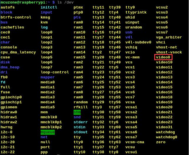
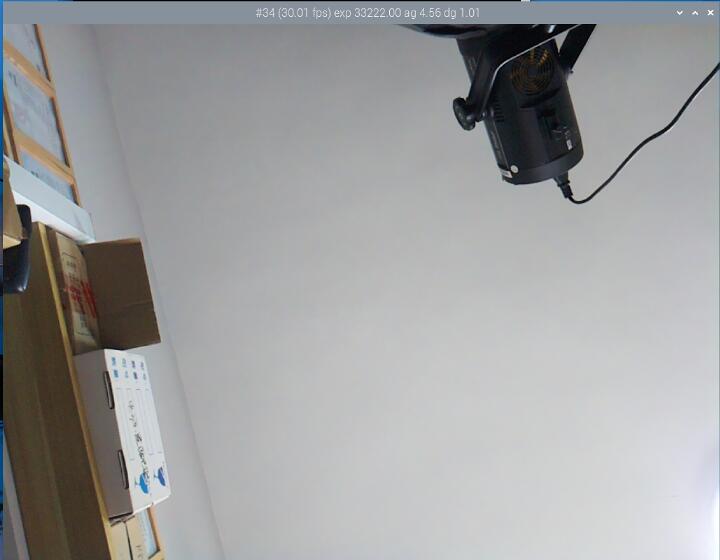
在终端中输入libcamera-hello --camera 0即可打开对应的摄像头浏览:

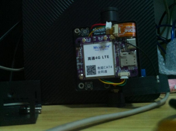
如果需要拍照,则输入:
libcamera-jpeg -o test.jpg

照片保存在/home/mcuzone目录下(即用户主目录),照片效果如下:
4.3 双HDMI测试
将扩展板上的两个HDMI口各插一个显示器,可实现一主一副双屏扩展显示,先插入的显示器为主屏。
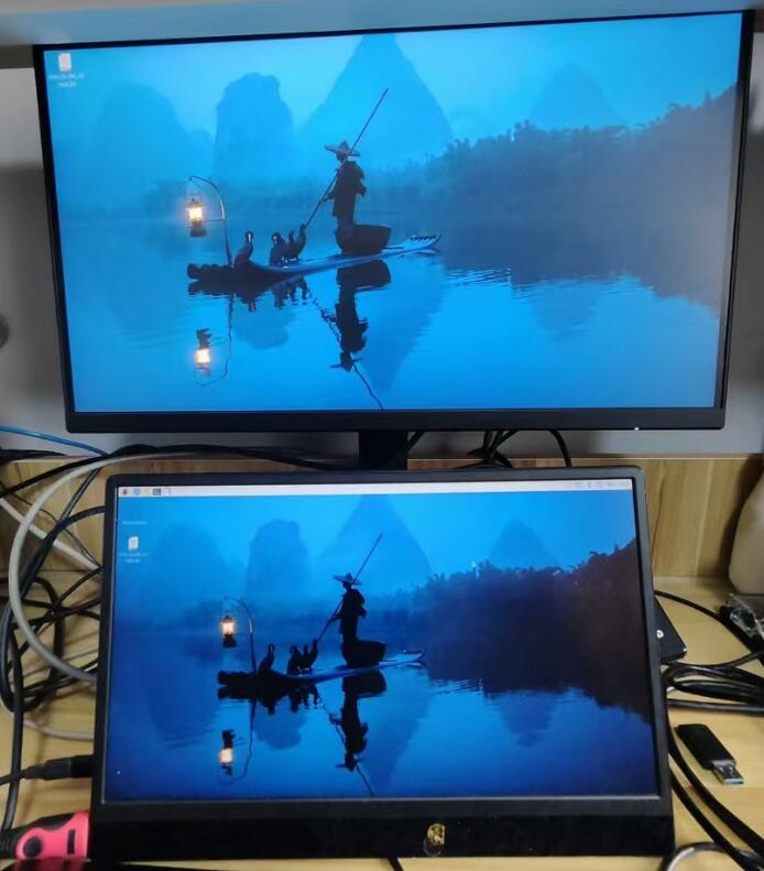

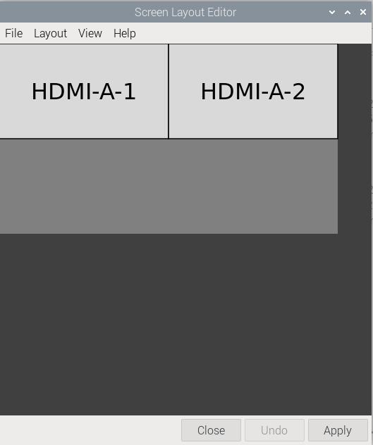
点击左上角的树莓派标志,Preferences下有个Screen Configuration:

打开软件后,可以在里面调节双屏的相对位置、分辨率、转向、刷新率等参数:
4.4 扩展4G模组测试
本扩展板有2个版本,连接4G模组的方法如下:
1. 如果你是A版本扩展板,用一根USB Type C-A线,将4G模组接到扩展板的USB Type A口;
2. 如果你是B版本扩展板,4G模组的1.25 4pin接口接到扩展板内置的1.25 4pin USB口,同时可以装进外壳。
下图左为A版本,右为B版本:
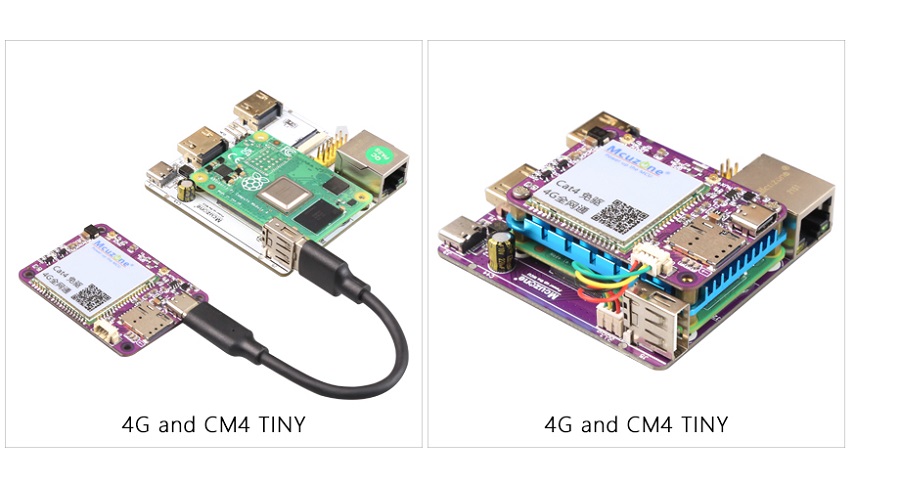
无论用哪种方法,都会占用扩展板的USB Type A口,因此此时无法使用键盘鼠标,需要用SSH软件通过网口去操作系统。
如果有必须使用键盘鼠标的需求,可以在扩展板A版本上接一个USB HUB,然后把4G模组和键鼠都接在USB HUB上。但是因为4G模组的能耗较大,因此建议使用带外接电源的USB HUB。
本文档使用的4G模组型号为CM4 4G mini(国产CAT4)。
正确连接扩展板和4G模组后,启动系统,在SSH软件中执行命令lsusb,如下图所示:

本模块的id为1286 4e3d。
在SSH软件中执行ifconfig -a,我们可以看到4G模块(eth1)已经正确获得了IP地址:
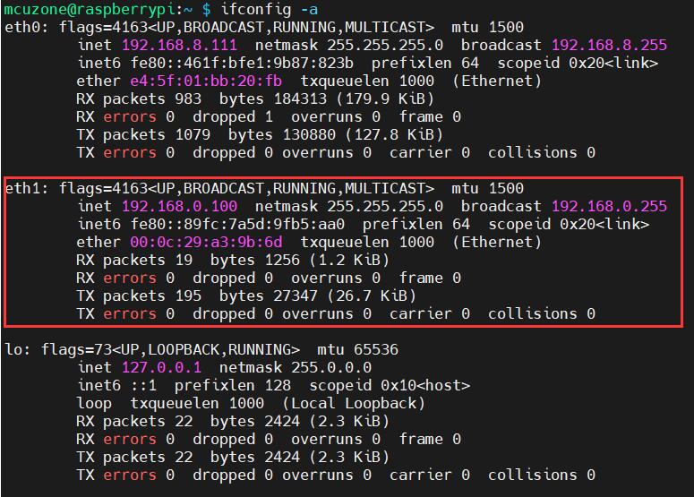
4G模组正确获得ip地址后,我们可以ping外网地址,如:
ping www.mcuzone.com

表示此时已经可以正常上网。
五、OpenWrt系统下的硬件测试
此扩展板搭配树莓派CM4核心板,在OpenWrt系统下可配置为一进一出的交换机模式:
方式一:扩展板上扩展4G模组可作为WAN口(直接4G上网),网口配置为LAN口,用于连接PC(4G进,有线网口出)。
方式二:CM4核心板自带的WiFi配置为WAN口(需要是带WiFi版本的CM4核心板),扩展板上网口配置为LAN口(WiFi进,网口出)。
本文使用的OpenWrt系统为:openwrt-bcm27xx-bcm2712-rpi-5-squashfs-sysupgrade-linux-6.1.100-20240805.img.gz
5.1 准备工作
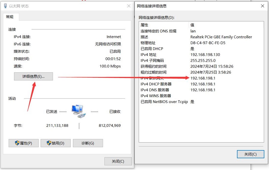
烧写OpenWrt系统并上电启动后,我们通过扩展板自带网口连接网线至PC网口,待PC的网卡与扩展板的网口连接成功后,我们在Windows设置中找到网络和Internet,在以太网中打开连接的网络查看默认网关的IP地址,这个地址就是OpenWrt系统的后台配置页面地址,如图所示,本文测试的地址为192.168.198.1:
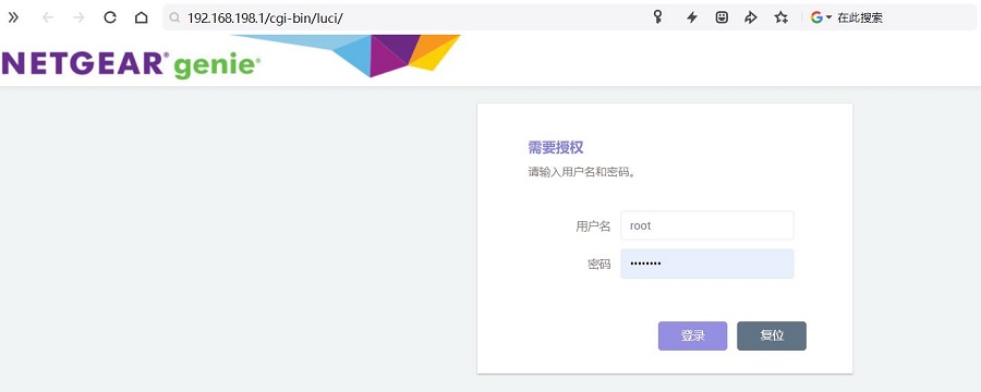
然后打开网页浏览器输入192.168.198.1进入OpenWrt系统。默认用户名为root,默认密码为password。
5.2 原生千兆网口测试
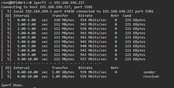
我们将扩展板自带网口连接网线至PC网口,现在扩展板的地址为192.168.198.1,PC的地址为192.168.198.227,在扩展板和PC之间使用使用iperf3进行测试:
原生千兆以太网测速结果,client模式为939Mbps左右
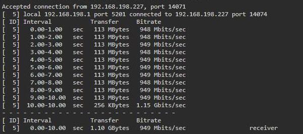
server模式为949Mbps左右:
注意:原生千兆网络测速受网络环境和测试方法影响,速度请以实际为准,本测试仅供参考。
5.3 4G进/千兆网口出上网测试
将4G模组使用USB Type C-A线或者1.25 4pin线与扩展板相连。
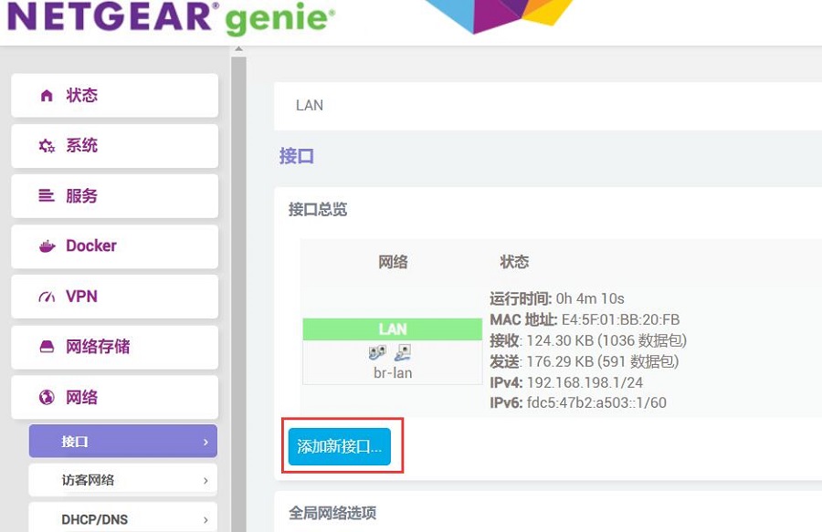
进入OpenWrt系统后,如前所述,用网线把扩展板的网口和PC的网口直连,然后进入”网络 - 接口“,点击”添加新接口“:
新接口的设置如下图,其中”eth1“即为4G模块:
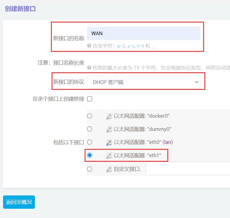
然后点击”提交“。
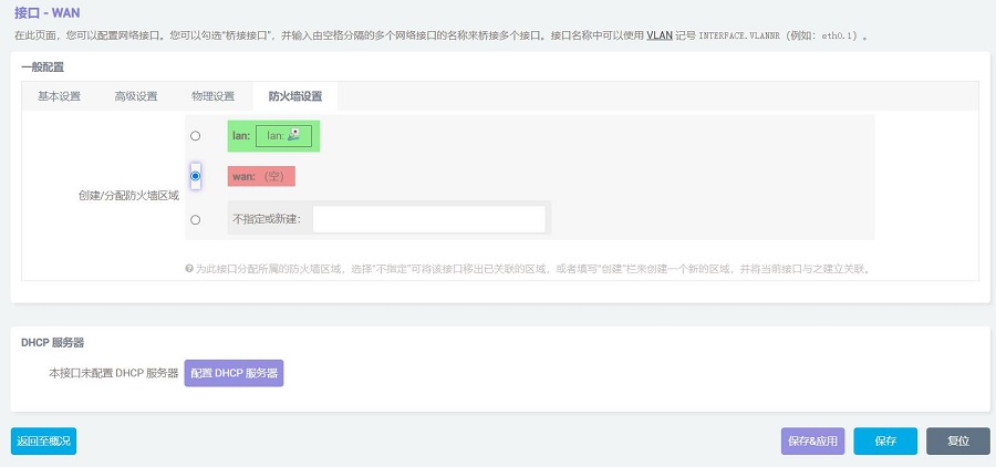
在”防火墙设置“中,区域选择”wan“,然后点击”保存&应用“:
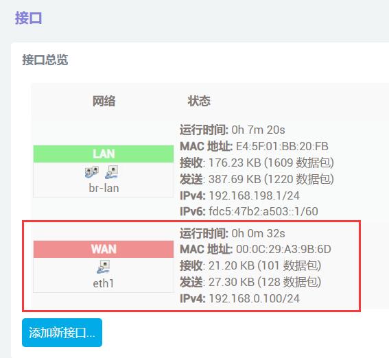
稍等片刻,我们在”网络 - 接口“中就能看到WAN口已经通过4G模块获得了IP:
此时我们在TTYD终端中,执行ifconfig -a,就能看到usb0的参数,ping公网地址也能成功,说明此时可以通过4G模块上网:

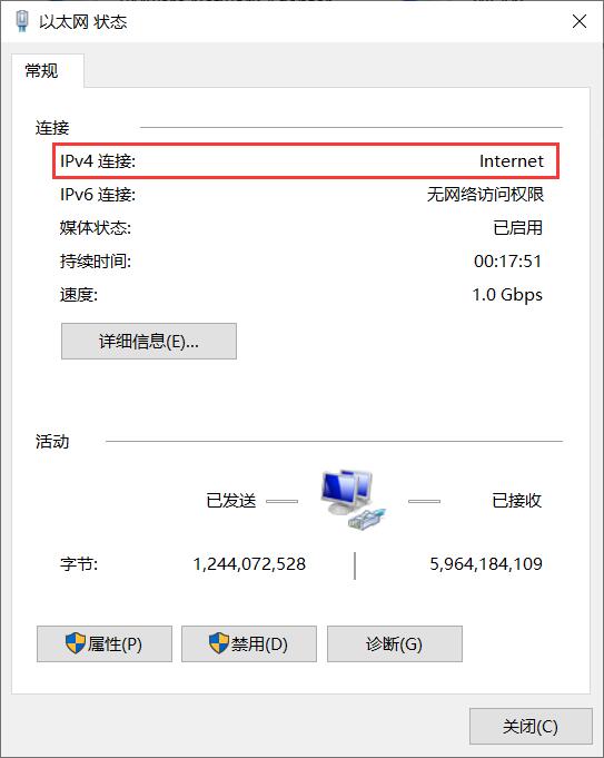
同时我们可以在与扩展板相连的PC的网卡连接中,看到以太网的连接状态是Internet,表示此时PC也可以通过这个4G模组上网:
5.4 WiFi进/千兆网口出上网测试
本测试需要使用带Wifi模块的树莓派CM4核心板。
进入OpenWrt系统后,如前所述,用网线把扩展板的网口和PC的网口直连,进入”网络 - 无线“,点击”扫描“:

加入一个无线网络:

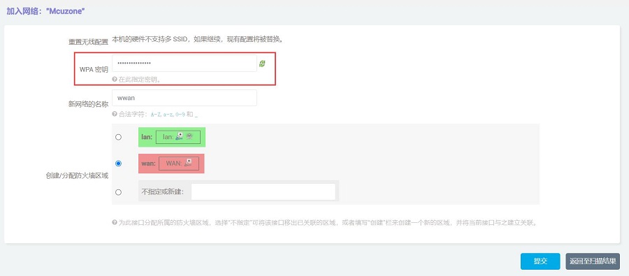
然后点击”提交“,在下一个页面点击”保存&应用“:

稍等片刻,我们就能在”网络 - 无线“中看到这个无线网卡已经连接网络成功:
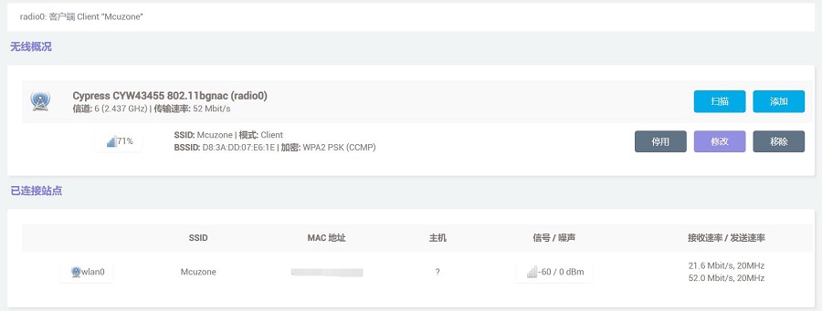
然后进入”网络 - 接口“,我们可以看到这个WWAN口已经获得了IP地址:
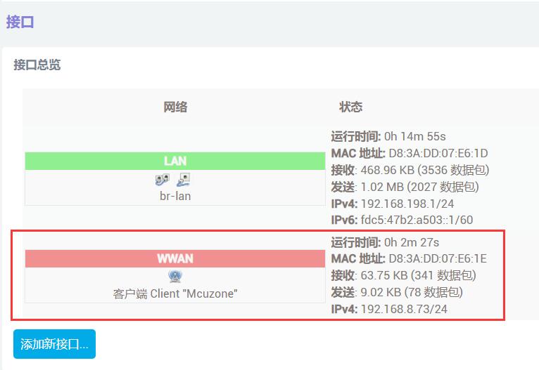
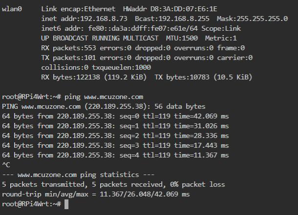
此时我们在TTYD终端中,执行ifconfig -a,就能看到wlan0的参数,ping公网地址也能成功,说明此时可以通过无线网卡上网:
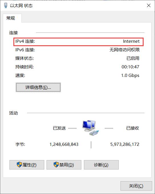
同时我们可以在与扩展板相连的PC的网卡连接中,看到以太网的连接状态是Internet,表示此时PC也可以通过这个无线网卡上网:
联系我们
电话:13957118045
如本页面有任何疏漏、错误或者侵权,请通过上述途径联系我们,谢谢!
Copyright 2004-2025 野芯科技


 QQ:8204136