1001 RPi0 4G CAT1-ETH(RS485 OPT:修订间差异
无编辑摘要 |
无编辑摘要 |
||
| 第42行: | 第42行: | ||
http://www.mcuzone.com/wiki/0007_Zero_4G_Cat1/0007_Zero_4G_Cat1_43.jpg | http://www.mcuzone.com/wiki/0007_Zero_4G_Cat1/0007_Zero_4G_Cat1_43.jpg | ||
== ''' | == '''Ⅲ、System flashing''' == | ||
3.1 | 3.1 The hardware in this document is based on the Raspberry Pi Zero 2W. The Raspberry Pi OS used in this document is: 2024-07-04-raspios-bookworm-arm64.img.xz(Raspberry Pi OS with desktop). | ||
( | (If you are using the Raspberry Pi Zero (1st generation) series boards, they only support 32-bit systems. Please be sure to download the correct version.) | ||
You can download the Raspberry Pi OS in: | |||
https://www.raspberrypi.com/software/operating-systems/#raspberry-pi-os-64-bit | https://www.raspberrypi.com/software/operating-systems/#raspberry-pi-os-64-bit | ||
Or ubuntu-24.04-preinstalled-server-arm64+raspi.img.xz (Ubuntu Server 24.04 LTS, The Raspberry Pi Zero 2W cannot use the Desktop version due to performance limitations.). | |||
You can download the Ubuntu OS in: | |||
https://ubuntu.com/download/raspberry-pi | https://ubuntu.com/download/raspberry-pi | ||
3.2 | 3.2 Use Imager or balenaEtcher to flash the OS image in TF card. [[0005 MPS2242 2280(单SSD扩展板)#3.2 从TF卡启动|Click here to read the instructions for System flashing]] | ||
== ''' | == '''Ⅲ、Demonstration of Using the Raspberry Pi OS''' == | ||
=== 4.1 | === 4.1 View hardware devices === | ||
==== 4.1.1 | ==== 4.1.1 View USB devices ==== | ||
Open the terminal in Raspberry Pi OS and enter the command<code>lsusb</code>, as shown in the image below: | |||
http://www.mcuzone.com/wiki/0007_Zero_4G_Cat1/0007_Zero_4G_Cat1_01.jpg | http://www.mcuzone.com/wiki/0007_Zero_4G_Cat1/0007_Zero_4G_Cat1_01.jpg | ||
The system has detected the USB hub and the 4G module: | |||
Device | Device 002:External USB Hub; | ||
Device | Device 003:4G module; | ||
Device | Device 004:USB to 100Mbps Ethernet adapter; | ||
Device 005:USB2.0- | Device 005:USB2.0-A Interface; | ||
Device 008:USB2.0- | Device 008:USB2.0-A Interface. | ||
If the system does not recognize the USB HUB and 4G module, please carefully check if the pogo pins are aligned with the gold-plated contacts. Also, please open the config.txt file located in the root directory of the TF card's system partition on the PC to check the USB initialization script: | |||
http://www.mcuzone.com/wiki/0007_Zero_4G_Cat1/0007_Zero_4G_Cat1_41.jpg | http://www.mcuzone.com/wiki/0007_Zero_4G_Cat1/0007_Zero_4G_Cat1_41.jpg | ||
Please verify if both of the red boxed areas in the image are fully configured. If not, please manually complete the configuration and save the file: | |||
<code># otg_mode=1</code> | <code># otg_mode=1</code> | ||
| 第92行: | 第92行: | ||
http://www.mcuzone.com/wiki/0007_Zero_4G_Cat1/0007_Zero_4G_Cat1_42.jpg | http://www.mcuzone.com/wiki/0007_Zero_4G_Cat1/0007_Zero_4G_Cat1_42.jpg | ||
==== 4.1.2 | ==== 4.1.2 View network devices ==== | ||
Open the terminal in Raspberry Pi OS and enter the command <code>ifconfig -a</code>, as shown in the image below: | |||
http://www.mcuzone.com/wiki/0007_Zero_4G_Cat1/0007_Zero_4G_Cat1_24.jpg | http://www.mcuzone.com/wiki/0007_Zero_4G_Cat1/0007_Zero_4G_Cat1_24.jpg | ||
We can see that eth0 is a USB-to-Ethernet adapter, and eth1 is a 4G Cat1 connection (with the IP address in the image above is 192.168.5.8). | |||
=== 4.2 | === 4.2 Test network devices === | ||
==== 4.2.1 | ==== 4.2.1 ping tests ==== | ||
When testing, there is a priority order: if eth0 is connected, it will be used first. If there are specific requirements for internal and external networks, please adjust the metric values of each network and the DNS server settings. | |||
Use the -I parameter to specify which network interface to start the ping packet from, as shown below: | |||
<code>ping www.mcuzone.com -I eth0</code> | <code>ping www.mcuzone.com -I eth0</code> | ||
| 第112行: | 第112行: | ||
http://www.mcuzone.com/wiki/0007_Zero_4G_Cat1/0007_Zero_4G_Cat1_04.jpg | http://www.mcuzone.com/wiki/0007_Zero_4G_Cat1/0007_Zero_4G_Cat1_04.jpg | ||
Priority can be checked by executing the <code>route</code> command; the network card with the smaller metric value will be preferred for communication. | |||
http://www.mcuzone.com/wiki/0007_Zero_4G_Cat1/0007_Zero_4G_Cat1_05.jpg | http://www.mcuzone.com/wiki/0007_Zero_4G_Cat1/0007_Zero_4G_Cat1_05.jpg | ||
We can also force communication through another network by disabling a specific network card. For example, to disable eth0, you can execute the following command: | |||
<code>sudo ifconfig eth0 down</code> | <code>sudo ifconfig eth0 down</code> | ||
And enable eth0 by the following command: | |||
<code>sudo ifconfig eth0 up</code> | <code>sudo ifconfig eth0 up</code> | ||
==== 4.2.2 | ==== 4.2.2 Set network adapter priority ==== | ||
To set the priority of network cards, you need to modify the metric value of the network card. First, we need to install the ifmetric software. | |||
<code>sudo apt install ifmetric</code> | <code>sudo apt install ifmetric</code> | ||
| 第131行: | 第131行: | ||
http://www.mcuzone.com/wiki/0007_Zero_4G_Cat1/0007_Zero_4G_Cat1_06.jpg | http://www.mcuzone.com/wiki/0007_Zero_4G_Cat1/0007_Zero_4G_Cat1_06.jpg | ||
After the installation is complete, you can modify the metric value of the network card. If you need to change the metric value of eth0 to 102, you can execute: | |||
<code>sudo ifmetric eth0 102</code> | <code>sudo ifmetric eth0 102</code> | ||
After making the changes, use the <code>route</code> command to check, and we can see that the metric value of eth0 has been updated to 102: | |||
http://www.mcuzone.com/wiki/0007_Zero_4G_Cat1/0007_Zero_4G_Cat1_07.jpg | http://www.mcuzone.com/wiki/0007_Zero_4G_Cat1/0007_Zero_4G_Cat1_07.jpg | ||
However, this modification is only temporary; if the system is restarted, it will revert to its original state. To permanently change the metric value of eth0 to 102, you need to edit the startup file to achieve this. | |||
Open rc.local by the following command: | |||
<code>sudo nano /etc/rc.local</code> | <code>sudo nano /etc/rc.local</code> | ||
Add the command you want to execute at startup above exit 0, such as <code>sudo ifmetric eth0 102</code>, then save the file. You can modify the metric of eth0 every time the system starts by this way. | |||
http://www.mcuzone.com/wiki/0007_Zero_4G_Cat1/0007_Zero_4G_Cat1_08.jpg | http://www.mcuzone.com/wiki/0007_Zero_4G_Cat1/0007_Zero_4G_Cat1_08.jpg | ||
| 第151行: | 第151行: | ||
http://www.mcuzone.com/wiki/0007_Zero_4G_Cat1/0007_Zero_4G_Cat1_09.jpg | http://www.mcuzone.com/wiki/0007_Zero_4G_Cat1/0007_Zero_4G_Cat1_09.jpg | ||
After modifying the metric values, it is possible that the system's nameserver (i.e., DNS server) is still using the previous higher-priority network card's nameserver. Since the default network card has now changed, this can lead to domain name resolution issues. So we also need to update the nameserver. | |||
Open resolv.conf by the following command: | |||
<code>sudo nano /etc/resolv.conf</code> | <code>sudo nano /etc/resolv.conf</code> | ||
| 第161行: | 第161行: | ||
http://www.mcuzone.com/wiki/0007_Zero_4G_Cat1/0007_Zero_4G_Cat1_17.jpg | http://www.mcuzone.com/wiki/0007_Zero_4G_Cat1/0007_Zero_4G_Cat1_17.jpg | ||
Check if the current nameserver is correct. If it is not, please change it to the nameserver of the network card with higher priority or to some common nameserver addresses (such as 8.8.8.8, etc.). | |||
==== 4.2.3 | ==== 4.2.3 Using udhcpc to specify DNS servers ==== | ||
In the previous section, we discussed specifying DNS servers by modifying the nameserver. In fact, we can also achieve this by using udhcpc. | |||
Install the udhcpc software: | |||
<code>sudo apt install udhcpc</code> | <code>sudo apt install udhcpc</code> | ||
| 第172行: | 第172行: | ||
http://www.mcuzone.com/wiki/0007_Zero_4G_Cat1/0007_Zero_4G_Cat1_48.jpg | http://www.mcuzone.com/wiki/0007_Zero_4G_Cat1/0007_Zero_4G_Cat1_48.jpg | ||
In this section, in the example we are testing, eth0 is a USB-to-Ethernet adapter, and usb0 is a 4G Cat1 (which corresponds to eth1 in the previous section). If we need to use the network DNS of the USB-to-Ethernet adapter (eth0), please use the following command: | |||
<code>sudo udhcpc -i eth0</code> | <code>sudo udhcpc -i eth0</code> | ||
| 第178行: | 第178行: | ||
http://www.mcuzone.com/wiki/0007_Zero_4G_Cat1/0007_Zero_4G_Cat1_49.jpg | http://www.mcuzone.com/wiki/0007_Zero_4G_Cat1/0007_Zero_4G_Cat1_49.jpg | ||
If we need to use the network DNS of the 4G Cat1 (usb0), please use the following command: | |||
<code>sudo udhcpc -i usb0</code> | <code>sudo udhcpc -i usb0</code> | ||
| 第184行: | 第184行: | ||
http://www.mcuzone.com/wiki/0007_Zero_4G_Cat1/0007_Zero_4G_Cat1_50.jpg | http://www.mcuzone.com/wiki/0007_Zero_4G_Cat1/0007_Zero_4G_Cat1_50.jpg | ||
==== 4.2.4 | ==== 4.2.4 Examples of how to use udhcpc ==== | ||
Example 1: The 100Mbps Ethernet port is connected to the Internet, and the 4G Cat1 is connected normally. In this case, if we ping a certain domain name, it will succeed: | |||
http://www.mcuzone.com/wiki/0007_Zero_4G_Cat1/0007_Zero_4G_Cat1_51.jpg | http://www.mcuzone.com/wiki/0007_Zero_4G_Cat1/0007_Zero_4G_Cat1_51.jpg | ||
At this point, unplugging the 100M network port cable will make the ping fail: | |||
http://www.mcuzone.com/wiki/0007_Zero_4G_Cat1/0007_Zero_4G_Cat1_52.jpg | http://www.mcuzone.com/wiki/0007_Zero_4G_Cat1/0007_Zero_4G_Cat1_52.jpg | ||
Run <code>sudo udhcpc -i usb0</code> and switch the DNS server to 4G Cat1, then you should be able to ping normally: | |||
http://www.mcuzone.com/wiki/0007_Zero_4G_Cat1/0007_Zero_4G_Cat1_53.jpg | http://www.mcuzone.com/wiki/0007_Zero_4G_Cat1/0007_Zero_4G_Cat1_53.jpg | ||
Example 2: The 100Mbps Ethernet port is connected to the internal network (not connected to the Internet), 4G Cat1 is connected normally. In this case, if we ping a certain domain name, it will failed: | |||
http://www.mcuzone.com/wiki/0007_Zero_4G_Cat1/0007_Zero_4G_Cat1_54.jpg | http://www.mcuzone.com/wiki/0007_Zero_4G_Cat1/0007_Zero_4G_Cat1_54.jpg | ||
Execute <code>sudo udhcpc -i usb0</code>, switch the DNS server to the 4G Cat1, and then you should be able to ping normally, and access internal network devices via the IP addresses: | |||
http://www.mcuzone.com/wiki/0007_Zero_4G_Cat1/0007_Zero_4G_Cat1_55.jpg | http://www.mcuzone.com/wiki/0007_Zero_4G_Cat1/0007_Zero_4G_Cat1_55.jpg | ||
==== 4.2.5 | ==== 4.2.5 Test speed by iperf3 ==== | ||
You can download iperf3 (Windows version) in: | |||
http://www.mcuzone.com/down/Software.asp?ID=10000634 | http://www.mcuzone.com/down/Software.asp?ID=10000634 | ||
Install iperf3 (Linux version) by using the following command: | |||
<code>sudo apt-get install iperf3</code> | <code>sudo apt-get install iperf3</code> | ||
100M Ethernet speed test results: It is about 70Mbps in client mode and it is about 90Mbps in server mode: | |||
http://www.mcuzone.com/wiki/0007_Zero_4G_Cat1/0007_Zero_4G_Cat1_10.jpg | http://www.mcuzone.com/wiki/0007_Zero_4G_Cat1/0007_Zero_4G_Cat1_10.jpg | ||
| 第224行: | 第220行: | ||
http://www.mcuzone.com/wiki/0007_Zero_4G_Cat1/0007_Zero_4G_Cat1_11.jpg | http://www.mcuzone.com/wiki/0007_Zero_4G_Cat1/0007_Zero_4G_Cat1_11.jpg | ||
''''' | '''''Note: The USB to 100M Ethernet adapter may not reach full speed due to the performance limitations of the Zero 2W, the USB hub, and the bandwidth usage of the 4G Cat1.''''' | ||
4G | 4G CAT1 speed test results: | ||
http://www.mcuzone.com/wiki/0007_Zero_4G_Cat1/0007_Zero_4G_Cat1_46.jpg | http://www.mcuzone.com/wiki/0007_Zero_4G_Cat1/0007_Zero_4G_Cat1_46.jpg | ||
'''''Note: Network speed tests are affected by network conditions and testing methods. The actual speed may vary; this test is for reference only.''''' | |||
== '''五、树莓派系统下4G Cat1模组的AT命令演示''' == | == '''五、树莓派系统下4G Cat1模组的AT命令演示''' == | ||
2024年8月16日 (五) 15:46的版本
Keywords
Raspberry Pi, Raspberry Pi Zero, Cat1 4G LTE, USB2.0-A, Ethernet, Expansion Board, USB HUB
Ⅰ、Introduction
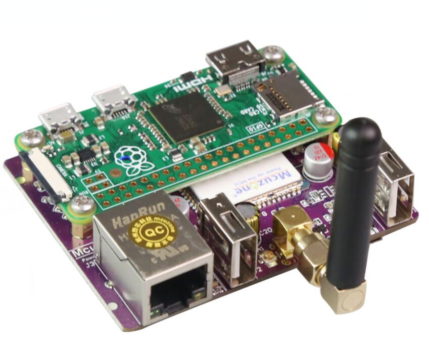
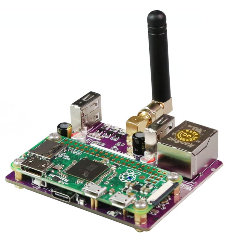
The Raspberry Pi Zero series (including Zero, Zero W(H), and Zero 2W) is a highly cost-effective embedded system platform with a compact size, low power consumption, and decent performance, making it suitable for many lightweight application scenarios. The Zero series, despite its compact size, offers many expansion interfaces. The underside of the board features gold-plated test points for USB and power connections. These USB and power test points allow us to connect various types of peripherals for expansion. This expansion board is a USB hub, connecting the expansion board to the USB port of the Zero via pogo pins. It extends four USB ports through the USB connection: one USB port is converted to a 100Mbps wired Ethernet connection, one USB port is connected to a 4G Cat1 module, and two USB2.0-A host interfaces are provided.
4G Cat1 is a cost-effective module designed for medium-speed IoT applications around 10Mbps. The 10Mbps downlink and 5Mbps uplink speeds can meet the vast majority of networking and transmission needs. It supports 4G full network coverage, including China Unicom, China Telecom, and China Mobile networks.
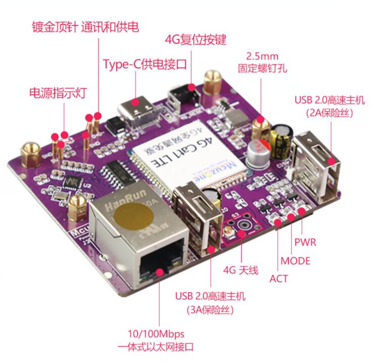
Ⅱ、Hardware Resources
2.1 Use gold-plated pogo pins to connect the Raspberry Pi Zero series, eliminating the need for external cables;
2.2 The two groups of gold-plated pogo pins are used separately for power supply and USB communication.
2.3 The expansion board is equipped with a USB-C power supply interface, which can power the entire system. The Micro USB port on the Zero can also be used for power.
2.4 The onboard USB hub expands the Zero's USB into four ports: one port is used for connecting a 4G LTE Cat1 module, two are USB host interfaces, and one is a USB to 10/100Mbps Ethernet adapter.
2.5 The 4G LTE Cat1 module supports full 4G network coverage, with a downlink speed of up to 10Mbps and an uplink speed of up to 5Mbps.
2.6 The 4G LTE Cat1 module is a plug-and-play in most systems, driver-free and does not require manual dialing, usually recognized as the eth1 network card.
2.7 The 4G LTE Cat module uses a Nano-sized SIM card and offers the option of either an SMA antenna or a first-generation IPEX antenna.
2.8 The expansion board supportsother Pi with USB contacts in the same position, such as the Orange Pi Zero 2W.
2.9 Onboard PWR/MODE/ACT LED.
2.10 Onboard reset button for 4G module.
Note 1: After connecting this expansion board, the Micro USB port on the Zero will no longer be usable.
Note 2: In some systems, it is necessary to disable the OTG function and set the USB mode to Host mode.
Note 3: The expansion board supports all versions of the Raspberry Pi Zero, including the Zero, Zero W, Zero WH, and Zero 2W.

Ⅲ、System flashing
3.1 The hardware in this document is based on the Raspberry Pi Zero 2W. The Raspberry Pi OS used in this document is: 2024-07-04-raspios-bookworm-arm64.img.xz(Raspberry Pi OS with desktop).
(If you are using the Raspberry Pi Zero (1st generation) series boards, they only support 32-bit systems. Please be sure to download the correct version.)
You can download the Raspberry Pi OS in:
https://www.raspberrypi.com/software/operating-systems/#raspberry-pi-os-64-bit
Or ubuntu-24.04-preinstalled-server-arm64+raspi.img.xz (Ubuntu Server 24.04 LTS, The Raspberry Pi Zero 2W cannot use the Desktop version due to performance limitations.).
You can download the Ubuntu OS in:
https://ubuntu.com/download/raspberry-pi
3.2 Use Imager or balenaEtcher to flash the OS image in TF card. Click here to read the instructions for System flashing
Ⅲ、Demonstration of Using the Raspberry Pi OS
4.1 View hardware devices
4.1.1 View USB devices
Open the terminal in Raspberry Pi OS and enter the commandlsusb, as shown in the image below:

The system has detected the USB hub and the 4G module:
Device 002:External USB Hub;
Device 003:4G module;
Device 004:USB to 100Mbps Ethernet adapter;
Device 005:USB2.0-A Interface;
Device 008:USB2.0-A Interface.
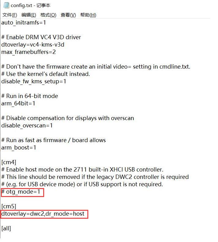
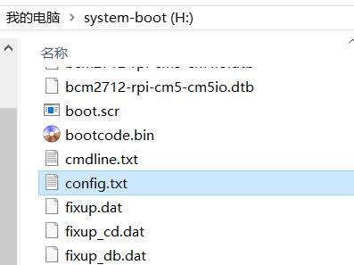
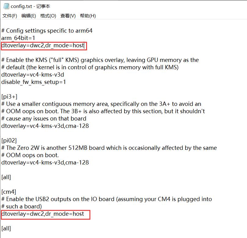
If the system does not recognize the USB HUB and 4G module, please carefully check if the pogo pins are aligned with the gold-plated contacts. Also, please open the config.txt file located in the root directory of the TF card's system partition on the PC to check the USB initialization script:
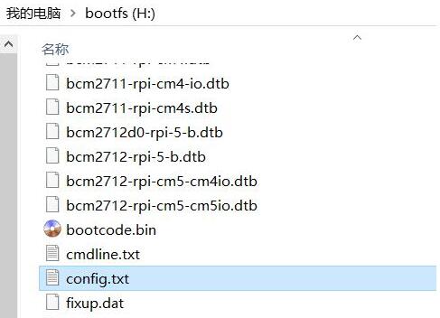
Please verify if both of the red boxed areas in the image are fully configured. If not, please manually complete the configuration and save the file:
# otg_mode=1
dtoverlay=dwc2,dr_mode=host
4.1.2 View network devices
Open the terminal in Raspberry Pi OS and enter the command ifconfig -a, as shown in the image below:
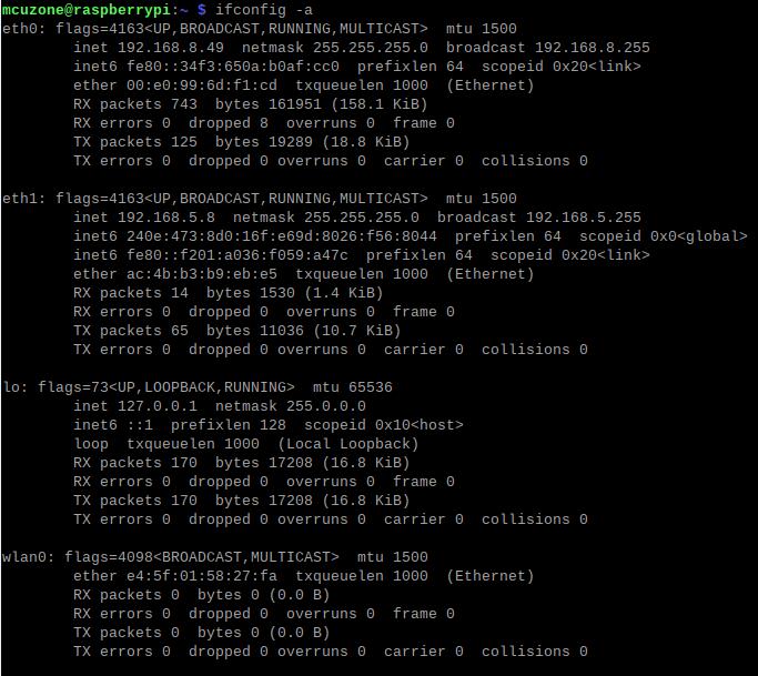
We can see that eth0 is a USB-to-Ethernet adapter, and eth1 is a 4G Cat1 connection (with the IP address in the image above is 192.168.5.8).
4.2 Test network devices
4.2.1 ping tests
When testing, there is a priority order: if eth0 is connected, it will be used first. If there are specific requirements for internal and external networks, please adjust the metric values of each network and the DNS server settings.
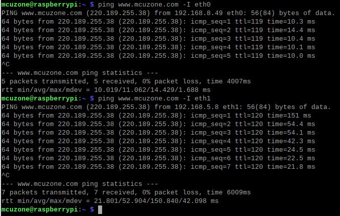
Use the -I parameter to specify which network interface to start the ping packet from, as shown below:
ping www.mcuzone.com -I eth0
ping www.mcuzone.com -I eth1
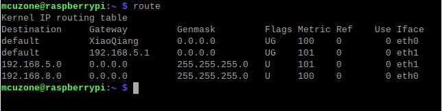
Priority can be checked by executing the route command; the network card with the smaller metric value will be preferred for communication.
We can also force communication through another network by disabling a specific network card. For example, to disable eth0, you can execute the following command:
sudo ifconfig eth0 down
And enable eth0 by the following command:
sudo ifconfig eth0 up
4.2.2 Set network adapter priority
To set the priority of network cards, you need to modify the metric value of the network card. First, we need to install the ifmetric software.
sudo apt install ifmetric

After the installation is complete, you can modify the metric value of the network card. If you need to change the metric value of eth0 to 102, you can execute:
sudo ifmetric eth0 102
After making the changes, use the route command to check, and we can see that the metric value of eth0 has been updated to 102:
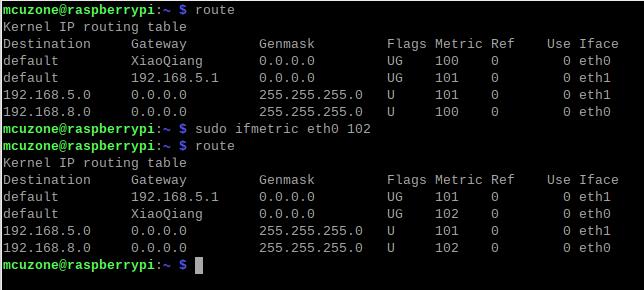
However, this modification is only temporary; if the system is restarted, it will revert to its original state. To permanently change the metric value of eth0 to 102, you need to edit the startup file to achieve this.
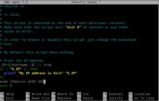
Open rc.local by the following command:
sudo nano /etc/rc.local
Add the command you want to execute at startup above exit 0, such as sudo ifmetric eth0 102, then save the file. You can modify the metric of eth0 every time the system starts by this way.

After modifying the metric values, it is possible that the system's nameserver (i.e., DNS server) is still using the previous higher-priority network card's nameserver. Since the default network card has now changed, this can lead to domain name resolution issues. So we also need to update the nameserver.
Open resolv.conf by the following command:
sudo nano /etc/resolv.conf

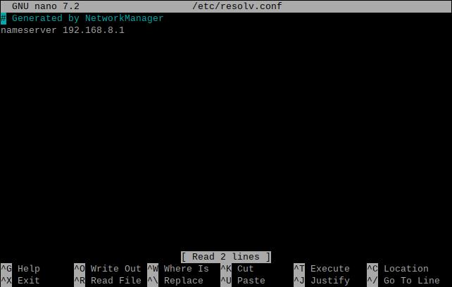
Check if the current nameserver is correct. If it is not, please change it to the nameserver of the network card with higher priority or to some common nameserver addresses (such as 8.8.8.8, etc.).
4.2.3 Using udhcpc to specify DNS servers
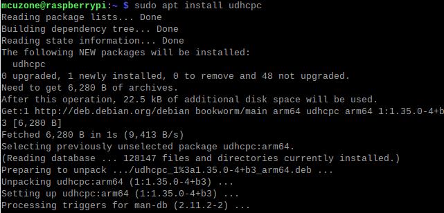
In the previous section, we discussed specifying DNS servers by modifying the nameserver. In fact, we can also achieve this by using udhcpc.
Install the udhcpc software:
sudo apt install udhcpc
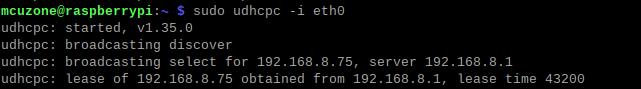
In this section, in the example we are testing, eth0 is a USB-to-Ethernet adapter, and usb0 is a 4G Cat1 (which corresponds to eth1 in the previous section). If we need to use the network DNS of the USB-to-Ethernet adapter (eth0), please use the following command:
sudo udhcpc -i eth0
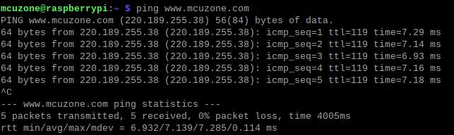
If we need to use the network DNS of the 4G Cat1 (usb0), please use the following command:
sudo udhcpc -i usb0

4.2.4 Examples of how to use udhcpc
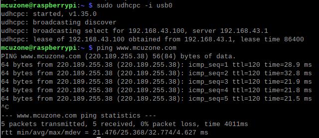
Example 1: The 100Mbps Ethernet port is connected to the Internet, and the 4G Cat1 is connected normally. In this case, if we ping a certain domain name, it will succeed:
At this point, unplugging the 100M network port cable will make the ping fail:

Run sudo udhcpc -i usb0 and switch the DNS server to 4G Cat1, then you should be able to ping normally:
Example 2: The 100Mbps Ethernet port is connected to the internal network (not connected to the Internet), 4G Cat1 is connected normally. In this case, if we ping a certain domain name, it will failed:

Execute sudo udhcpc -i usb0, switch the DNS server to the 4G Cat1, and then you should be able to ping normally, and access internal network devices via the IP addresses:
4.2.5 Test speed by iperf3
You can download iperf3 (Windows version) in:
http://www.mcuzone.com/down/Software.asp?ID=10000634
Install iperf3 (Linux version) by using the following command:
sudo apt-get install iperf3
100M Ethernet speed test results: It is about 70Mbps in client mode and it is about 90Mbps in server mode:
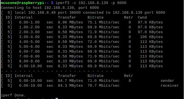
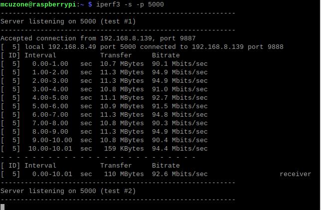
Note: The USB to 100M Ethernet adapter may not reach full speed due to the performance limitations of the Zero 2W, the USB hub, and the bandwidth usage of the 4G Cat1.
4G CAT1 speed test results:
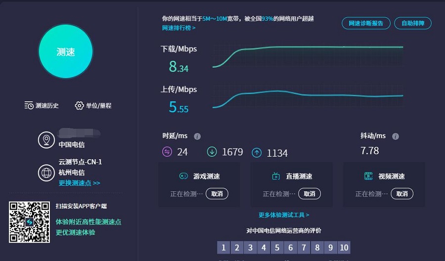
Note: Network speed tests are affected by network conditions and testing methods. The actual speed may vary; this test is for reference only.
五、树莓派系统下4G Cat1模组的AT命令演示
5.1 打开AT命令串口方法
在树莓派下要对4G进行AT命令操作,首先要打开AT命令串口,打开方法如下:
5.1.1 打开ttyUSB串口
输入命令lsusb,如下图所示:
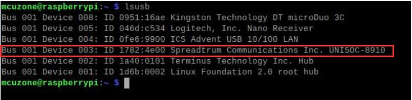
记下4G模块的ID值:1782 4e00
使用下列命令打开ttyUSB串口,其中echo后面的值就是上面记录的ID值:
sudo modprobe option
sudo sh -c 'echo 1782 4e00 > /sys/bus/usb-serial/drivers/option1/new_id'

执行以上两条命令后系统应该会多出ttyUSB0-2三个设备。
5.1.2 用串口工具打开
下载minicom工具:
sudo apt-get install minicom

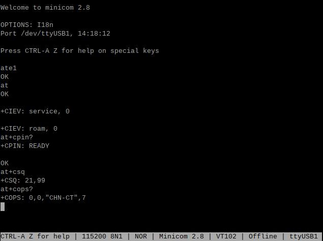
通过minicom打开AT命令串口:
sudo minicom -D /dev/ttyUSB0
或
sudo minicom -D /dev/ttyUSB1

然后直接键入AT命令,回车可以看到结果,如果需要查看回显,请键入命令:ate1。
注意:4G模组型号可能会变更,但流程一样,只需要用lsusb查看实际的USB ID并在后续命令中将USB ID替换为实际值即可。另外,有部分4G Cat1模组的芯片组ID已经被内核加入支持列表,这类Cat1模组无需添加USB ID即可自动识别为ttyAMAx。
5.2 常用AT命令
1) 检查SIM卡是否识别到:
at+cpin?
返回ready表示卡已识别,返回error要检查硬件
2) 检查天线信号质量:
at+csq
返回值在26-31表示信号OK,信号满格31;返回值在20-25表示信号勉勉强强;返回值在20以下表示信号比较糟糕或者天线没接
3) 检查注网情况:
at+cops?
正常应该返回运营商代码和7,7代表4G
注意,以上命令只有at+csq不要加问号,另外两条命令需要加问号。
4) 查看SIM卡的IMEI码:
at+cgsn
5) 重启4G模块(有时候如果重插SIM卡,热插拔不一定管用,可以用这个reset命令来复位模块):
at+reset
6) 关闭射频:
at+cfun=0
开启射频:
at+cfun=1
上述两条命令成对使用,可以在不重启4G模组的情况下让模组重新注网。
六、Ubuntu系统下使用演示
6.1 编辑初始化脚本
Ubuntu Server烧写完毕后,请在PC端打开TF卡系统分区根目录下的config.txt检查USB的初始化脚本,Ubuntu Server对USB初始化了两遍,前面一遍没有配置成host模式,需要确认下图中的两处红框的位置是否都配置成完全,如果没有,请手动添加完整:
dtoverlay=dwc2,dr_mode=host
6.2 配置用户名和密码
将TF卡插入Zero 2W,启动系统。第一次启动后会要求登录,用户名和密码均为ubuntu,登录成功后会要求修改密码。
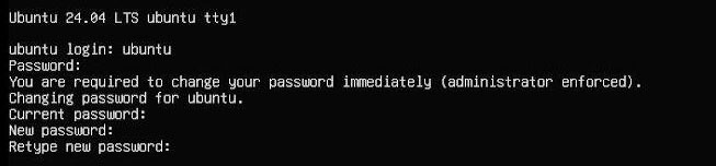
修改完毕后就自动进入系统。
6.3 配置网络
系统启动后并无网络可用,需要进行后续设置后才能使用。
注意,系统默认并没有集成ifconfig工具,只有ip命令可用。
执行ip addr查看并记录下网卡名称:
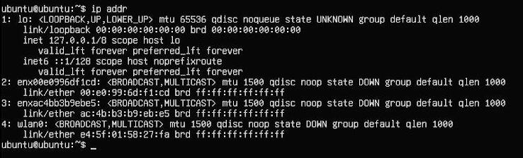
其中2号网卡(enx00e0996df1cd)为USB转百兆网卡,3号网卡(enxac4bb3b9ebe5)为4G模组。
然后运行下面的命令,打开网卡配置文件:
sudo nano /etc/netplan/50-cloud-init.yaml
按照下图编辑网卡配置文件:
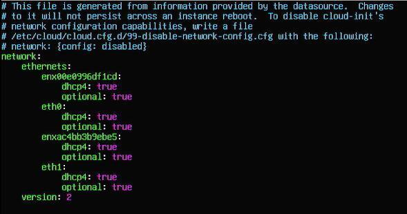
保存退出,然后重启。
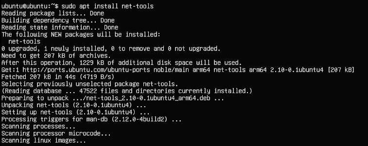
重启后即可联网,安装net-tools工具以便于使用:
sudo apt install net-tools
6.4 网络及4G模组测试
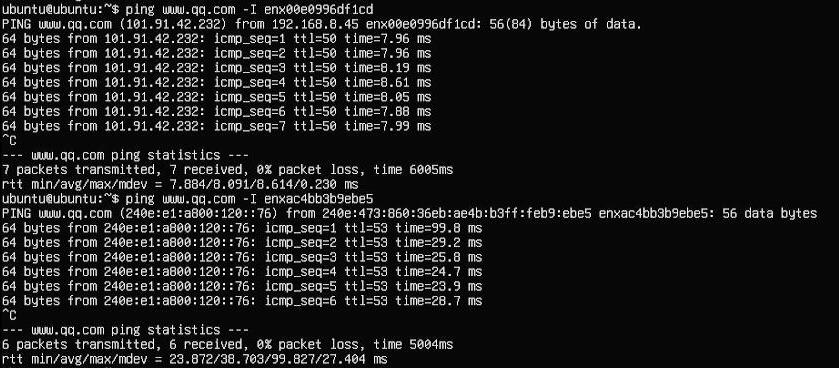
执行命令ifconfig -a,查看网卡信息:
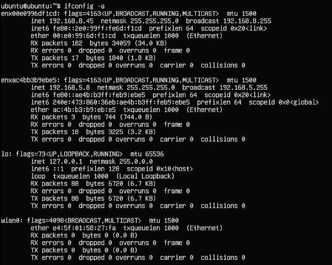
可见第一块网卡为USB转百兆网卡,第二块网卡为4G模组。
通过使用-I参数,在ping包时加上网卡名称,可指定哪块网卡进行ping包。通过这两块网卡对腾讯的网站的ping包测试可知,第二块网卡即4G模组支持ipv6:
6.5 AT命令交互测试
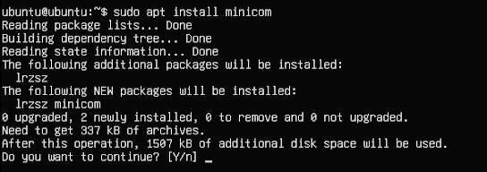
安装minicom工具:
sudo apt-get install minicom
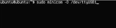
然后和树莓派OS一样,通过minicom打开AT命令串口:
sudo minicom -D /dev/ttyUSB0
或
sudo minicom -D /dev/ttyUSB1
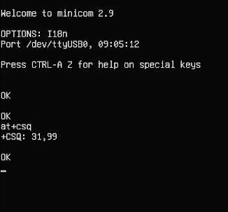
即可使用常见AT命令进行交互:
七、OpenWrt系统操作演示
7.1 概述
此扩展板搭配树莓派Zero 2W,在OpenWrt系统下可配置为一进一出的交换机模式,扩展板上的4G可作为WAN口(直接4G上网),网口配置为LAN口,用于连接PC。
7.2 准备工作
本文使用的OpenWrt系统为:openwrt-bcm27xx-bcm2709-rpi-2-squashfs-sysupgrade-linux-6.1.98-20240723.img.gz
烧写OpenWrt系统并上电启动后,我们通过树莓派自带网口连接网线至PC网口,待PC的网卡与树莓派的网口连接成功后,我们在Windows设置中找到网络和Internet,在以太网中打开连接的网络查看默认网关的IP地址,这个地址就是OpenWrt系统的后台配置页面地址,如图所示,本文测试的地址为192.168.198.1:
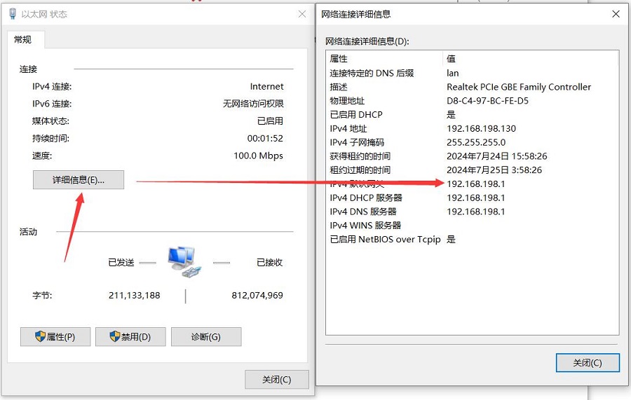
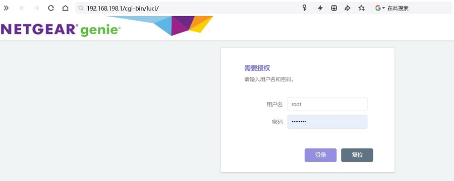
然后打开网页浏览器输入192.168.198.1进入OpenWrt系统。默认用户名为root,默认密码为password。
7.3 设置OpenWrt系统
进入OpenWrt系统后,如前所述,用网线把树莓派的网口和PC的网口直连,等PC的网卡获取了IP地址后,即可让PC直接通过4G模块上网(无需设置)。
7.4 测试4G模块网速
在PC端打开https://www.speedtest.cn/进行测速,此时流量走的是4G模块,测试结果如下:
注意:4G网络测速受网络信号和测试方法影响,速度请以实际为准。
7.5 挂载U盘及文件操作
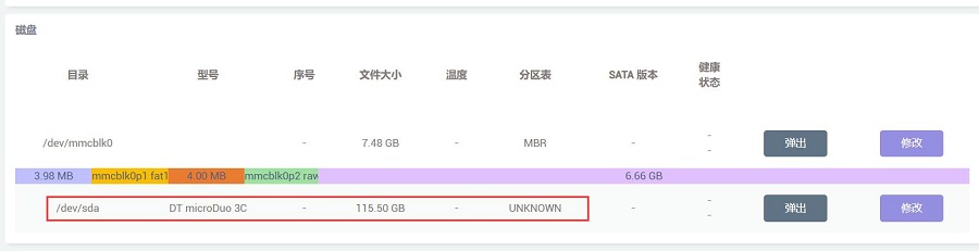
将U盘插入USB口,则在“系统 - 磁盘管理”中直接可以看到该U盘的信息及挂载情况:
在“系统 - 挂载点”中可以看到各个挂载点的情况,也可以在此页面对其进行配置。
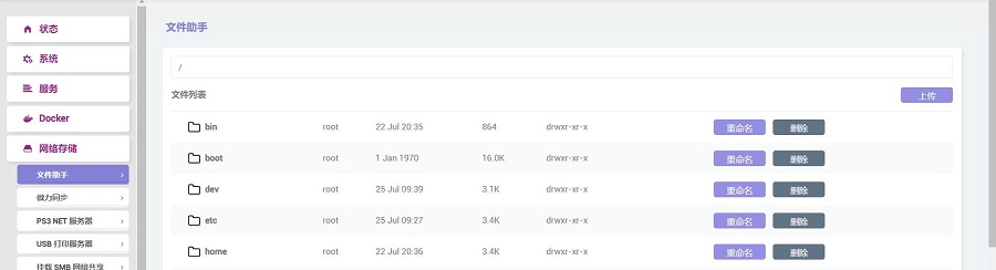
在“网络存储 - 文件助手”中,可以对系统中的文件进行操作。
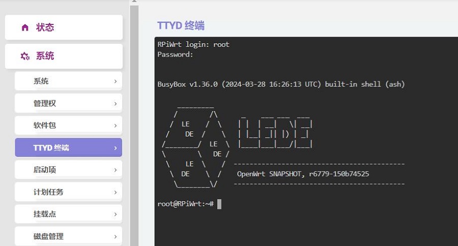
7.6 TTYD终端
OpenWrt系统自带一个网页版的TTYD终端,可在“系统 - TTYD终端”中打开。默认用户名为root,默认密码为password,因为是使用root账号登录,登录后即有root权限。
联系我们


 QQ:8204136
电话:13957118045
如本页面有任何疏漏、错误或者侵权,请通过上述途径联系我们,谢谢!
Copyright 2004-2025 野芯科技