0020 MPU4G(PCIe to USB 4G LTE EN:修订间差异
| 第231行: | 第231行: | ||
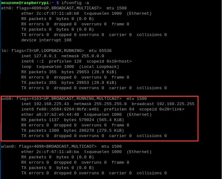
Once the net-tools package is installed, you can use the command <code>ifconfig -a</code> to check the network status. | Once the net-tools package is installed, you can use the command <code>ifconfig -a</code> to check the network status. | ||
http://www.mcuzone.com/wiki/0020_MP4GM/ | http://www.mcuzone.com/wiki/0020_MP4GM/0020_MP4GM_60.jpg | ||
It is evident that both the wired network card and the 4G module have obtained IP addresses at this point. | It is evident that both the wired network card and the 4G module have obtained IP addresses at this point. | ||
2025年2月24日 (一) 13:41的版本
Keywords
Raspberry Pi 5, Raspberry Pi, 4G LTE, PCIe, mini PCIe, AT Commands
I. Introduction
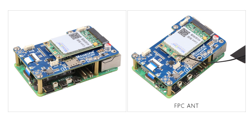
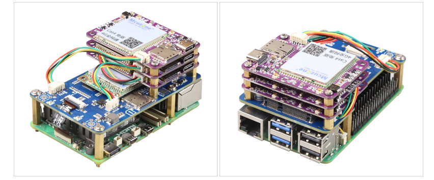
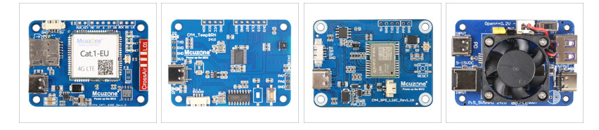
The MPU4G is a 4G expansion board specifically designed for the Raspberry Pi 5. First, expand four USB 2.0 interfaces through the PCIe interface, then connect one of the USB 2.0 signals to the 4G module on the miniPCIe interface. The remaining three USB 2.0 interfaces are brought out in the form of a 1.25mm 4Pin connector. These three interfaces can be used to further expand 1-3 CM4-sized 4G modules. When expanding more than two 4G modules, please pay attention to the power supply. They can also be used to expand our temperature and humidity modules or GPS modules. The 4G modules included with the expansion board are driver-free and do not require dial-up. They are automatically recognized and plug-and-play under the Raspberry Pi official OS/Ubuntu, eliminating the need for additional driver installation. Their target applications include 4G access, multi-4G carrier aggregation, and remote unattended operation.
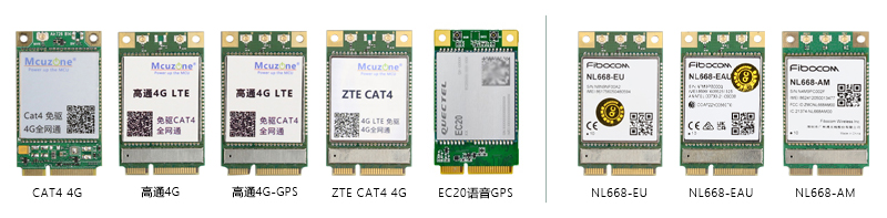
The MiniPCIe 4G models are as follows: Domestic solution CAT4 4G and ZTE CAT4 4G, Quectel EC20-GPS Voice Lite version (with call and SMS functions), Qualcomm 4G, and Qualcomm 4G-GPS version. There are also international versions, such as the Qualcomm 4G European version (NL668-EU), Australian version (NL668-EAU), and North American version (NL668-AM), among others.
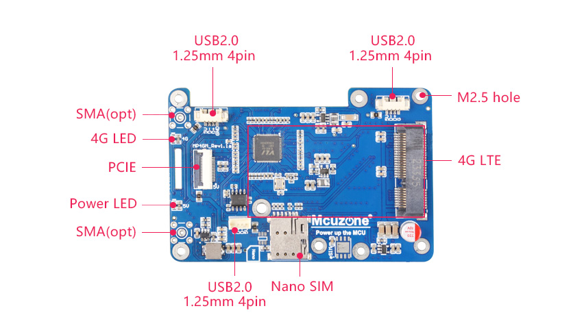
II. Hardware Spec
1. One PCIe interface, 0.5mm 16P, used to connect to the Raspberry Pi 5's own PCIe interface, and PCIe expands to 4 USB ports.
2. One Mini PCIe 4G LTE interface.
3. One Nano SIM card slot, single SIM single standby.
4. Triple-channel USB 2.0 interface, 1.25mm-4P, can be used to expand 1-3 channels of 4G.
5. Two LED lights, one serving as the power indicator and the other as the 4G status light.
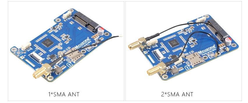
6. Reserve two 4G SMA antenna interfaces.
7. Reserve two 4G SMA antenna interfaces.
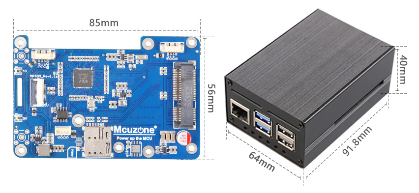
8. Size: 85*56mm. Fully compatible with the Raspberry Pi 5 in terms of size and mounting holes. The board features a grooved design that does not interfere with the GPIO of the Raspberry Pi 5.
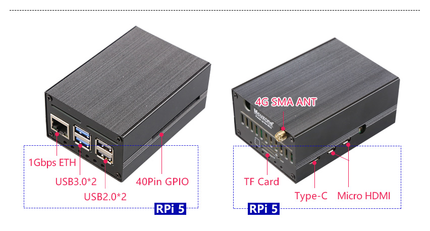
9. Aluminum alloy casing(OPT.)
| CAT4 | Qualcomm 4G/GPS | ZTE CAT4 | EC20-GPS Voice lite version | |
|---|---|---|---|---|
| BAND | LTE FDD:B1/3/5/8
LTE TDD:B34/38/39/40/41 |
LTE FDD:B1/3/5/8
LTE TDD:B34/38/39/40/41 WCDMA:B1/8 TDSCDMA:B34/39 EVDO/CDMA1X:BC0 GSM/GPRS/EDGE:900/1800MHz(OPT) |
LTE FDD:B1/3/5/8
LTE TDD:B34/38/39/40/41 |
LTE FDD:B1/3/5/8
LTE TDD:B34/38/39/40/41 WCDMA:B1/8 TDSCDMA:B34/39 CDMA:BC0 GSM:900/1800MHz |
III. Work with Raspberry Pi OS
Raspberry Pi OS: 2024-07-04-raspios-bookworm-arm64.img.xz
You can download it in:
https://www.raspberrypi.com/software/operating-systems/#raspberry-pi-os-64-bit
Different 4G models recognize different device models, usually as eth1 or usb0 devices.
3.1 Qualcomm 4G module
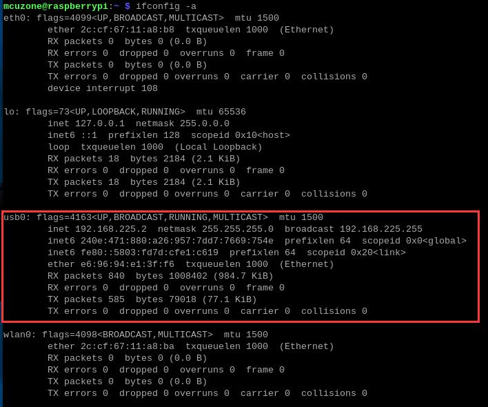
By executing ifconfig -a in the Raspberry Pi terminal, we can see that the 4G module (usb0) has successfully obtained an IP address.
Under normal conditions, the "4G" LED indicator on the expansion board will blink slowly, with occasional brief fast flashes in between.
3.2 CAT4 4G module
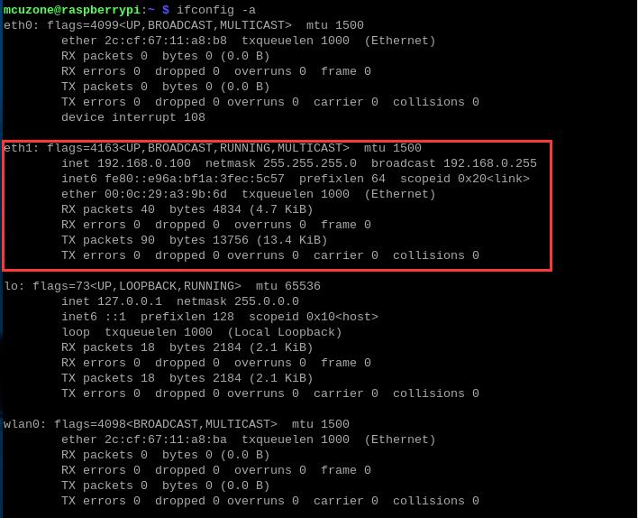
By executing ifconfig -a in the Raspberry Pi terminal, we can see that the 4G module (eth1) has successfully obtained an IP address.
Under normal conditions, the "4G" LED indicator on the expansion board will blink slowly (the duration of the light being on is longer than the duration of it being off).
3.3 ZTE CAT4 4G module
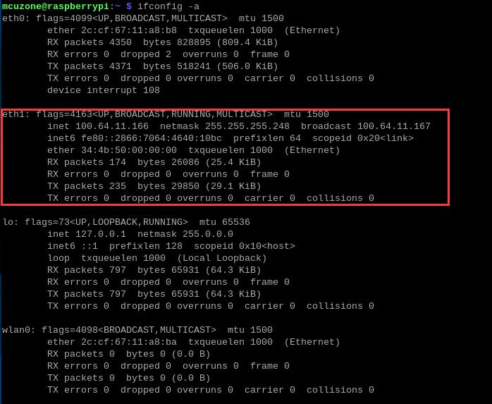
By executing ifconfig -a in the Raspberry Pi terminal, we can see that the 4G module (eth1) has successfully obtained an IP address.
Under normal conditions, the "4G" LED indicator on the expansion board flashes rapidly."
3.4 Quectel EC20-GPS voice lite version
By executing ifconfig -a in the Raspberry Pi terminal, we can see that the 4G module (usb0) has successfully obtained an IP address.
Under normal conditions, the "4G" LED indicator on the expansion board will blink slowly.
3.5 Internet test
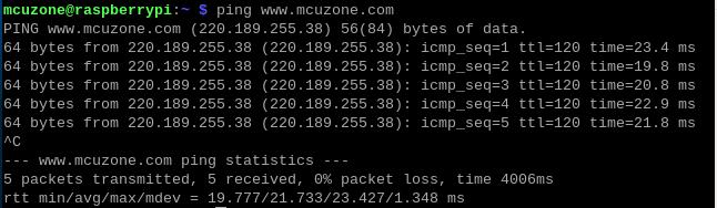
After the 4G module successfully obtains an IP address, we can ping external network addresses, such as:
ping www.mcuzone.com
It is also possible to connect to the external network via a 4G module and access a speed test website to measure the speed, with the results as follows:
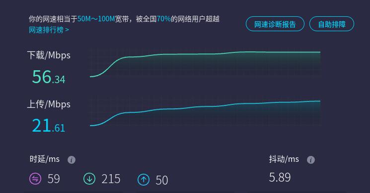
Note: Network speed tests are affected by the network environment and testing methods. Please refer to the actual speed, as this test is for reference only.
3.6 Remote Connection to Raspberry Pi(4G application)
If you want to use 4G for remote access to a Raspberry Pi 5, the official Raspberry Pi OS (Bookworm version) comes with an example application called Raspberry Pi Connect that you can refer to and use. With the Raspberry Pi paired with 4G, and through the official remote control software Raspberry Pi Connect, you can securely access your Raspberry Pi from anywhere in the world. Here, we will demonstrate how to configure the remote connection service.
The configuration and usage instructions are as follows:
1. Apply for a Raspberry Pi ID at https://id.raspberrypi.com/.
2. Install the Raspberry Pi Connect software in the Raspberry Pi OS (no need to install if it is already installed):
sudo apt install rpi-connect
3. Restart the system, and in the GUI, sequentially select the items as shown in the following image to ensure that Raspberry Pi Connect is turned on:
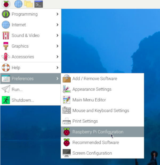
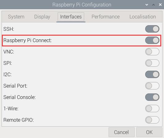
4. In the upper right corner, there will be a Raspberry Pi Connect icon.
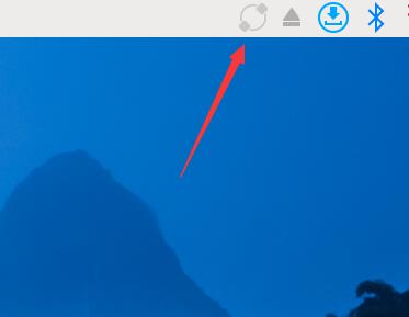
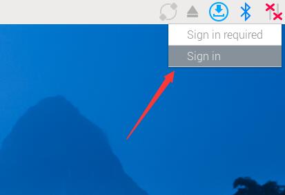
5. Click on this icon, select "Sign in" and use your previously registered Raspberry Pi ID to log in on the pop-up webpage. Then set the device name.
6. After successfully logging in, access https://connect.raspberrypi.com/ in a browser on Windows and log in.
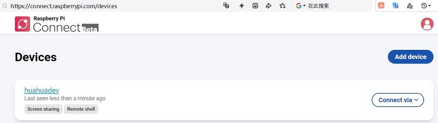
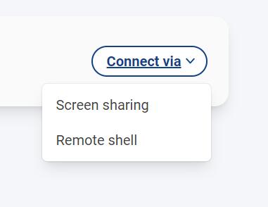
7. Click "Connect via" to choose between using Screen sharing or the Remote shell Interface.
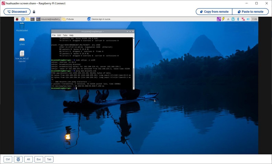
8. Screen sharing is as follows:
The remote command line interface is as follows:
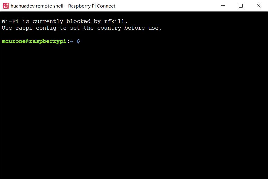
9. Measured data usage: Under remote desktop, the Raspberry Pi consumes about 2MB of data per minute; under The remote shell is as follows: line interface, the Raspberry Pi consumes about 100KB of data per minute.
IV. Work with Ubuntu OS
Ubuntu OS:
ubuntu-24.04-preinstalled-desktop-arm64+raspi.img.xz(Desktop, GUI version)
ubuntu-24.04-preinstalled-server-arm64+raspi.img.xz(Server, command line version)
You can download it in:
https://ubuntu.com/download/raspberry-pi
4.1 Ubuntu Desktop OS
Ubuntu Desktop OS(GUI version). When executing ifconfig -a in the terminal, all 4G modules are recognized as network interfaces starting with enx, and they can be used directly without the need for drivers or additional configuration.
4.2 Ubuntu Server OS
When the Ubuntu Server OS (command line version) is used on a Raspberry Pi 5, only one network interface is enabled by default, and the Wi-Fi functionality is disabled. So if you want to use 4G or WiFi, you need to enable the second and third network interfaces, and manually add a network card to use them. We will demonstrate the steps to enable Wi-Fi and use 4G on Ubuntu Server.
4.2.1 System flashing and setting up SSH
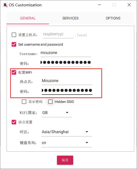
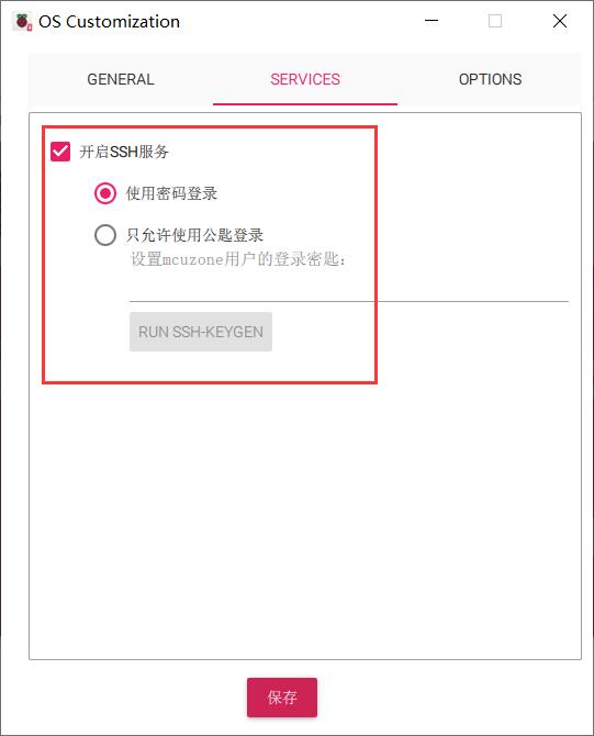
When flashing the system, it is recommended to pre-configure the WiFi and SSH settings in the Raspberry Pi imager.
Insert the TF card into the Raspberry Pi and boot up the system. The login username and password are the ones pre-configure; if not pre-configure, both are ubuntu, and you will be prompted to change the password after successful login.
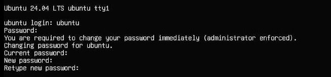
After the modifications are completed, it will automatically enter the system.
4.2.2 Configure system network
The operation here is demonstrated using CAT 4G as an example.
Note: The system does not come with the ifconfig tool by default, only the ip command is available.
Execute ip addr to view and record the network interface name.
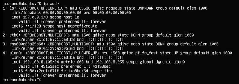
Among them, eth0 is the built-in Gigabit Ethernet port of the Raspberry Pi 5, enx000c29a39b6d is the 4G module, and wlan0 is the Raspberry Pi's own wireless network card (the system has been pre-configured with wireless hotspot information during the initial setup, so the wireless network card can be used immediately after booting).
Then run the following command to open the network card configuration file:
sudo nano /etc/netplan/50-cloud-init.yaml
Please edit the network card configuration file according to the image below:
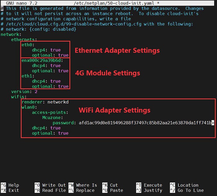
Save and exit, then reboot.
After rebooting, you can connect to the internet. Install the net-tools package for ease of use:
sudo apt install net-tools
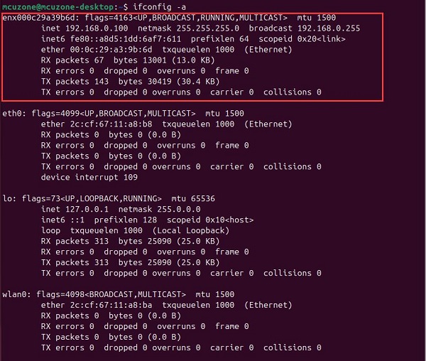
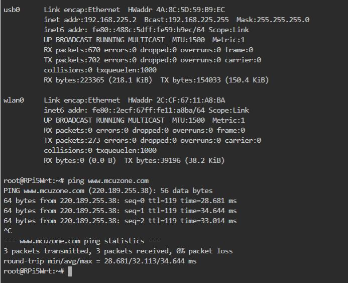
Once the net-tools package is installed, you can use the command ifconfig -a to check the network status.
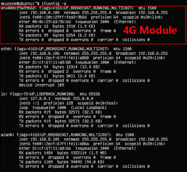
It is evident that both the wired network card and the 4G module have obtained IP addresses at this point.
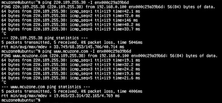
"By ping an external server through a specific network card, we can verify whether the network card is functioning properly. For example, if we ping an external IP address and website using a 4G module, the results are as follows:"
ping 220.189.255.38 -I enx000c29a39b6d
ping www.mcuzone.com -I enx000c29a39b6d
V. AT command operation
5.1 AT command operation
Taking Qualcomm 4G as an example, execute lsusb in terminal:
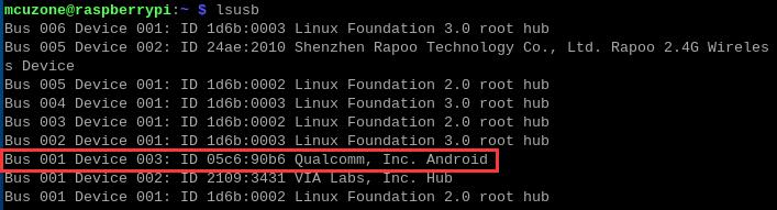
Record the ID value of the 4G module: 05c6 90b6 (The ID number for each type of module varies; please refer to the actual details for accurate information.)
Use the following command to open the ttyUSB serial port, where the value after echo is the ID recorded above:
sudo modprobe option
sudo sh -c 'echo 05c6 90b6 > /sys/bus/usb-serial/drivers/option1/new_id'
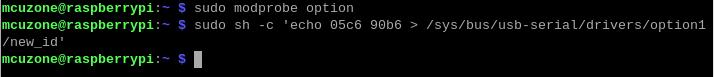
After executing the above two commands, proceed with:
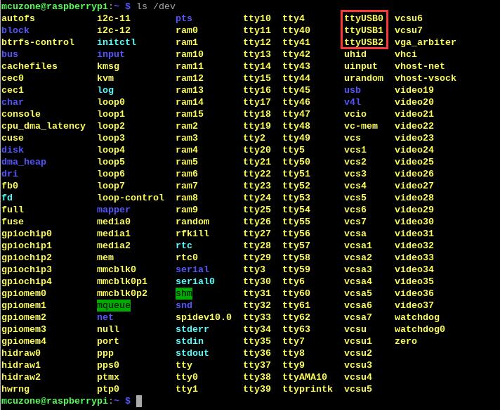
ls /dev
At this point, you should be able to see three devices under the dev directory: ttyUSB0, ttyUSB1, and ttyUSB2:
Install the serial port software minicom:
sudo apt install minicom
Then open the AT command serial port using minicom:
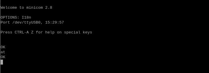
sudo minicom -D /dev/ttyUSB0

(Note: The choice of which serial port to use should be based on the ability to input and run AT commands after entering this port, ensuring that the display is not garbled and the results do not jump erratically.)
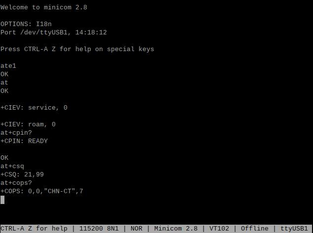
The first time you enter an AT command, there may be no echo. If you then input the command at and press Enter, and it returns "OK," it indicates that everything is working properly. If you need to check the echo, please type the command: ate1, then press Enter. After that, you can continue to type other commands and press Enter to see the results.
5.2 Common AT commands
1. Check if the SIM card is detected:
at+cpin?
Return ready to indicate the card has been recognized, if return error, you need to check the hardware.
2. Check antenna signal quality:
at+csq
eturn values between 26 and 31 indicate a good signal, with 31 representing a full signal strength; return values between 20 and 25 indicate a barely acceptable signal; return values below 20 indicate a poor signal or that the antenna might not be connected.
3. Check network registration status:
at+cops?
Normally, it should return the network supporter's code: 7, where 7 represents 4G.
Note: The above command at+csq should not include a question mark, while the other two commands require a question mark.
4. View the SIM card's IMEI code:
at+cgsn
5. Reset 4G module (Sometimes, if you reinsert the SIM card, hot swapping may not work; in such cases, you can use this reset command to reset the module.):
at+reset
6. Disable radio frequency:
at+cfun=0
Enable radio frequency:
at+cfun=1
The two commands mentioned above can be used in pairs to allow the module to re-register with the network without restarting the 4G module.
7. APN settings:
The SIM card of a regular mobile phone can be used directly without any configuration. However, some IoT cards require APN settings to function properly, and the APN parameters are usually provided by the carrier.
If you need the operation methods for other AT commands, please refer to the AT command manual provided with the 4G module (the operation commands may vary depending on the manufacturer).
5.3 Modify the IP address of the 4G module
如果出厂的4G IP地址和用户使用的IP地址有冲突,或有修改IP地址的需求,可按照下列步骤进行修改:
If the default 4G IP address assigned at the factory conflicts with the IP address being used by the user, or if there is a need to modify the IP address, you can change the 4G module's IP.
1. CAT4 4G:
Execute the AT command:
AT+ROUTEIP=<newip>
Note: only addresses in the format of 192.168.x.1 are supported. If you set AT+ROUTEIP=192.168.3.1, the final IP address obtained will be 192.168.3.100. After making the changes, you need to power off and restart the OS.
Query current IP: AT+ROUTEIP?, it returns two values, the first one is the old IP, and the second one is the new IP.
Test command: AT+ROUTEIP=?
2. Qualcomm 4G, ZTE CAT4 4G:
Set the 4G module's IP to directly obtain a public IP. Please execute the AT command:
Set the IP to public: AT+GTIPPASS=1
Set the IP to private: AT+GTIPPASS=0
Check whether the current IP is a public or private IP: AT+GTIPPASS?
After modifying the IP, a power cycle reboot is required for the changes to take effect.
3. We are not know how to modify the IP address of EC20, If needed, users are required to research it themselves.
5.4 GPS test
5.4.1 Qualcomm 4G-GPS
To use the GPS function of Qualcomm 4G, you need to connect a GPS passive antenna and ensure that the GPS antenna is extended outdoors. GPS is operated via AT commands.
Follow the steps in section 5.1 to enable the ttyUSB serial port.
Run minicom and open the ttyUSB0 serial port.
sudo minicom -D /dev/ttyUSB0
And execute:
at+gtgpsepo=1 //Enable AGPS
at+gtgpspower=1 //Enable GPS
Please wait a moment for the positioning to succeed, then execute:
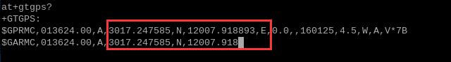
at+gtgps? //View NMEA messages
Then you can see the GPS information output:
5.4.2 Quectel EC20-GPS voice lite version
5.4.2.1 Operation of GPS
To use the GPS function of EC20, you need to connect a GPS active antenna and ensure that the GPS antenna is extended outdoors. GPS is operated via AT commands.
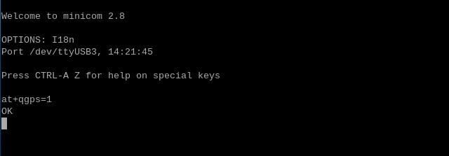
Open ttyUSB3 serial port by minicom:
sudo minicom -D /dev/ttyUSB3
and execute:
AT+QGPS=1
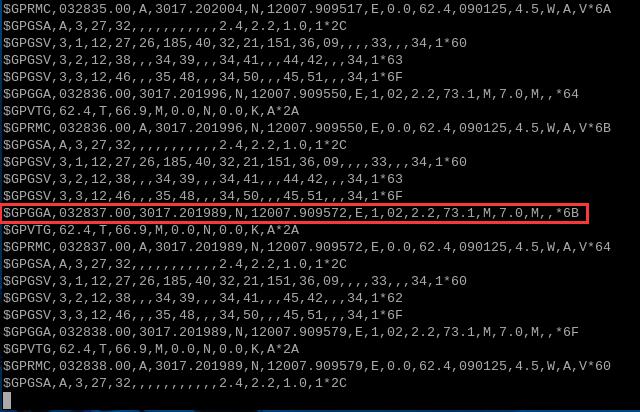
Open ttyUSB1 serial port by minicom, and you can obtain GPS information:
sudo minicom -D /dev/ttyUSB1
If you find the raw GPS data in minicom not very intuitive, we can install gpsd to extract the GPS information:
sudo apt-get install gpsd gpsd-clients

Then configure the gpsd software:
sudo gpsd /dev/ttyUSB1 -N -D 9 -F /var/run/gpsd.sock -S 3333

Note: 3333 is the listening port, which can be customized as needed.
Do not close the configuration terminal window, instead, open a new terminal window and execute:
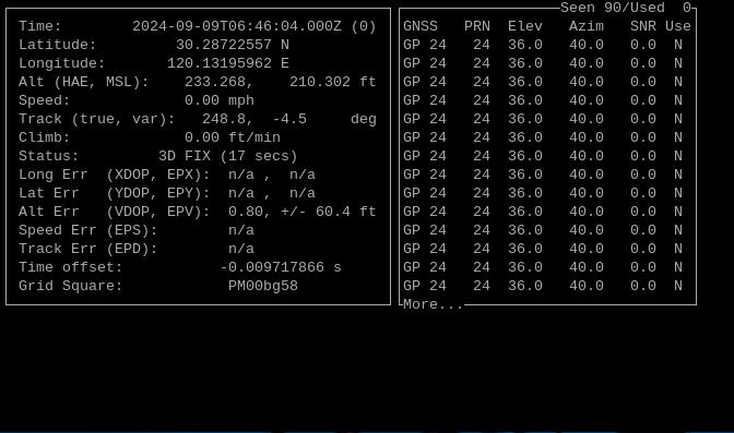
cgps -s localhost:3333

From the output interface, information such as time, latitude and longitude, speed, and altitude can be seen.
5.4.2.2 Send SMS
Sending text messages involves using AT commands. Here, we will introduce the process of sending SMS using English characters.
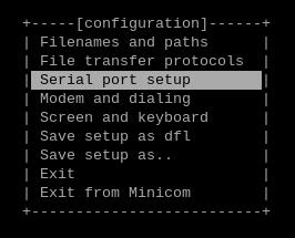
Follow the steps in section 5.1 to enable the ttyUSB serial port. Then execute sudo minicom -s, select "Serial port setup":
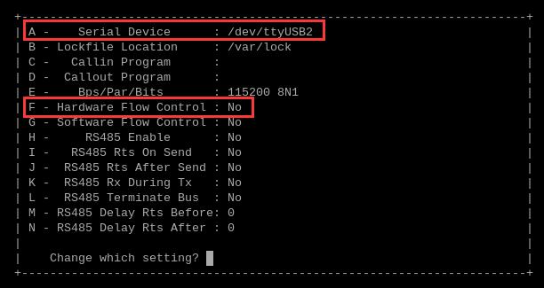
Press A and F to modify the serial port number and flow control as shown in the figure below:
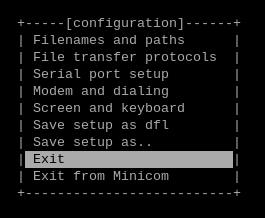
After making the modifications, press Enter to return to the previous menu, and select "Exit" to quit:
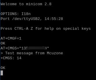
Execute the following AT commands in sequence:
AT+CMGF=1 //Set the SMS characters to English
AT+CMGS="13xxxxxxxxx" //Set the number to receive SMS messages
After pressing Enter, input the SMS content after the ">", then press Ctrl+Z to send. A successful send will display "+CMGS 14":

5.5 Some knowledge about network policies
If you need to learn about some network strategy knowledge, you can refer to the following link:
How to set network adapter priority
Using udhcpc to specify DNS servers
VI. Work with OpenWrt
The version of the OpenWrt we use for testing is: openwrt-bcm27xx-bcm2712-rpi-5-squashfs-sysupgrade-linux-6.1.100-20240805.img.gz
Taking the Qualcomm 4G module as an example, in the OpenWrt, it can be configured in a one-in-one-out switch mode. This means the 4G can serve as the WAN port, while the Raspberry Pi 5's own Ethernet port can be configured as the LAN port for connecting to a PC.
6.1 Login operation interface
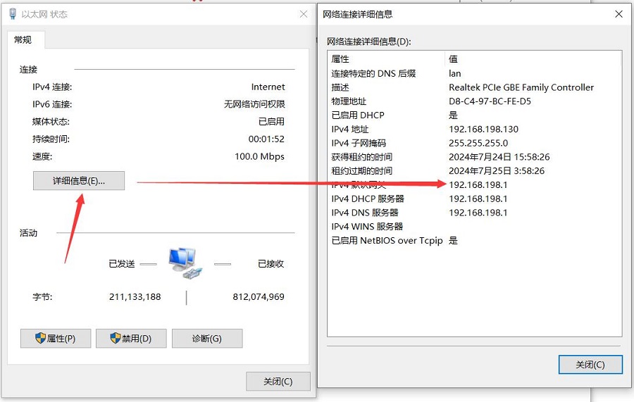
Connect the Raspberry Pi 5 to the PC's Ethernet port, start the system, go to Network and Internet settings in Windows, open the connected network in Ethernet, and view the default gateway's IP address. This address is the backend configuration page address for the OpenWrt. As shown in the figure, the address tested in this article is 192.168.198.1:
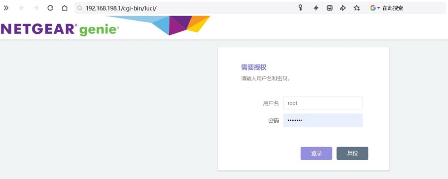
Then open your web browser, enter 192.168.198.1 to access the OpenWrt. The default username is root, and the default password is password.
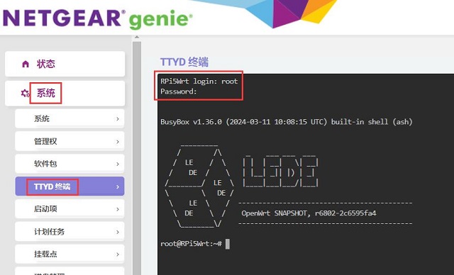
After logging in, navigate to "System - TTYD Terminal", and log in using the username root and the password password.
By entering ifconfig -a, you can see a network card labeled as usb0, which is the Qualcomm 4G module.
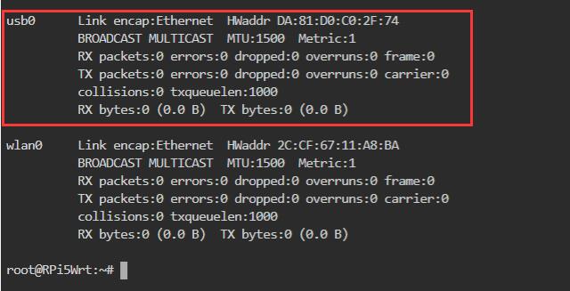
If it is a CAT4 4G or ZTE CAT4, the system recognizes it as eth1. If it is an EC20, it is also recognized as usb0. When setting up the interface later, simply change usb0 to eth1.
6.2 Set the 4G module as the WAN port
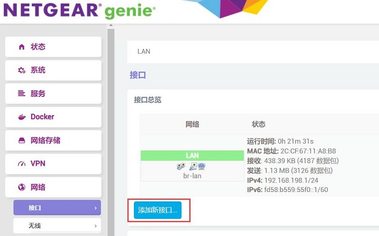
After entering the OpenWrt, navigate to "Network - Interfaces" and click "Add new interface".
The setup of the new interface is as shown in the figure below, where "usb0" represents the 4G module.
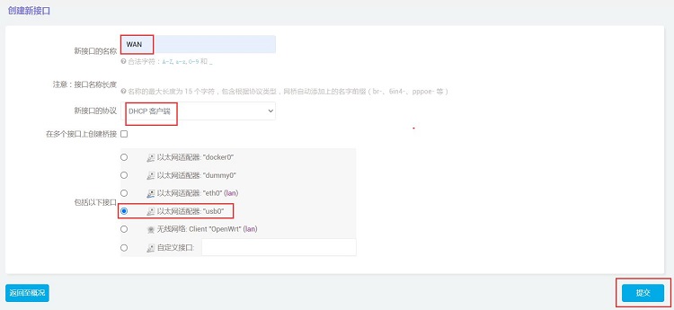
Then click "Submit".
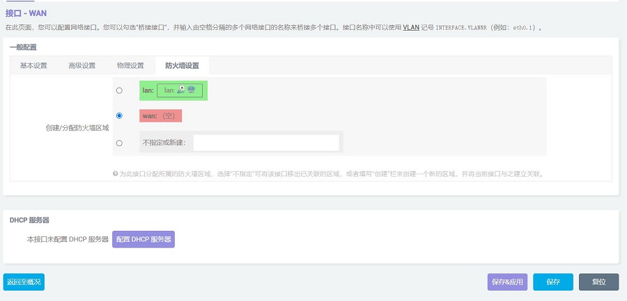
In the "Firewall Settings", select the "WAN", then click "Save & Apply".
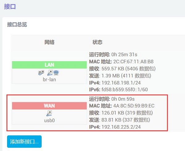
Wait a moment, and we will see in the "Network - Interfaces" that the WAN port has already obtained an IP through the 4G module.
Now we click the "System - TTYD Terminal", by executing ifconfig -a, we can see that usb0 has successfully obtained an IP address, and pinging a public address is also successful. This indicates that we can now access the internet via the 4G module.
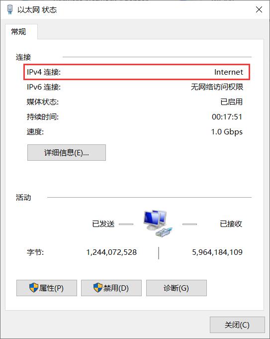
Meanwhile, we can observe in the network connection settings of the PC connected to the Raspberry Pi that the Ethernet connection status is labeled as "Internet", indicating that the PC can also access the internet through this 4G module at this time.
Open https://www.speedtest.cn/ on your PC to conduct a speed test. At this point, the traffic is routed through the 4G module, and the test results are as follows:
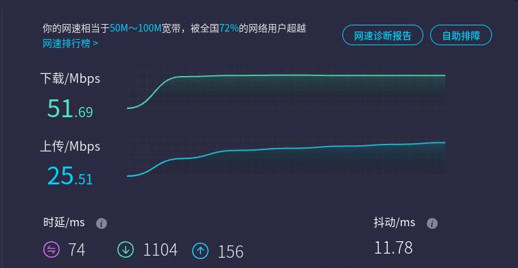
Note: Network speed tests are affected by the network environment and testing methods. Please refer to the actual speed, as this test is for reference only.
联系我们


 QQ:8204136
电话:13957118045
如本页面有任何疏漏、错误或者侵权,请通过上述途径联系我们,谢谢!
Copyright 2004-2025 野芯科技