4001 R3S 4G EN:修订间差异
(创建页面,内容为“== '''关键词''' == 友善 NanoPi R3S、RK3566、4G LTE、FriendlyWrt、OpenWrt、Ubuntu == '''一、简介''' == R3S的4G是一款基于友善NanoPi R3S开发板设计的一款4G LTE套件。以我司CM4 4G mini(高通4G LTE)模块为基础,设计了R3S的4G载板和配套的3D打印底座而组成。3D打印底座是用于替代R3S外壳的底座,且将4G天线内置。4G模块在友善官方固件里免驱,自动识别,无需额外装驱动…”) |
无编辑摘要 |
||
| 第1行: | 第1行: | ||
[[4001 R3S 4G|切换语言为中文]] | |||
== ''' | == '''Keywords''' == | ||
FriendlyElec NanoPi R3S、RK3566、4G LTE、FriendlyWrt、OpenWrt、Ubuntu | |||
== '''I. Introduction''' == | |||
The 4G module for the R3S is a 4G LTE kit designed specifically for the FriendlyElec NanoPi R3S development board. It is based on our CM4 4G mini (Qualcomm 4G LTE) module, around which we have designed a 4G carrier board for the R3S along with a matching 3D-printed base to compose the set. The 3D printed base is designed to replace the R3S enclosure base and incorporates an integrated 4G antenna. The 4G module is supported out-of-the-box by the official Friendly firmware, with automatic detection and no need for additional driver installation. | |||
The 4G module is a USB device that connects to the USB port of the R3S. For customers who have purchased an integrated kit that includes both a 4G module and an R3S from our company, we can assist with modifications if required. The modification involves transforming the USB cable of the 4G module to be fully internal, eliminating the need for a USB adapter board. However, after this modification, the USB port on the R3S will no longer be able to connect to any other USB devices. | |||
http://www.mcuzone.com/wiki/4001_Friendly_NanoPi_R3S/4001_Friendly_NanoPi_R3S_47.jpg | http://www.mcuzone.com/wiki/4001_Friendly_NanoPi_R3S/4001_Friendly_NanoPi_R3S_47.jpg | ||
| 第12行: | 第14行: | ||
http://www.mcuzone.com/wiki/4001_Friendly_NanoPi_R3S/4001_Friendly_NanoPi_R3S_48.jpg | http://www.mcuzone.com/wiki/4001_Friendly_NanoPi_R3S/4001_Friendly_NanoPi_R3S_48.jpg | ||
== ''' | == '''II. Work with FriendlyWrt''' == | ||
The R3S development board comes in two versions: one without eMMC (which requires the system to be booted from a TF card), and another with eMMC (which allows the system to be booted either from the eMMC or from a TF card). All demonstrations in this document use the version that boots the system from a TF card. Different boot methods require corresponding different firmware packages. Please ensure that you match the correct firmware package to your boot method. | |||
The version of the FriendlyElec system we tested: rk3566-sd-ubuntu-noble-core-6.1-arm64-20241114.img.gz | |||
The 4G module is used as a WAN port in the FriendlyWrt system. Connect the R3S's LAN port to the PC's network port using an Ethernet cable. Open a web browser on the PC and navigate to 192.168.2.1 to log in to the FriendlyWrt system backend page (the default username is <code>root</code> and the password is <code>password</code>). | |||
=== 2.1 Test 4G module === | |||
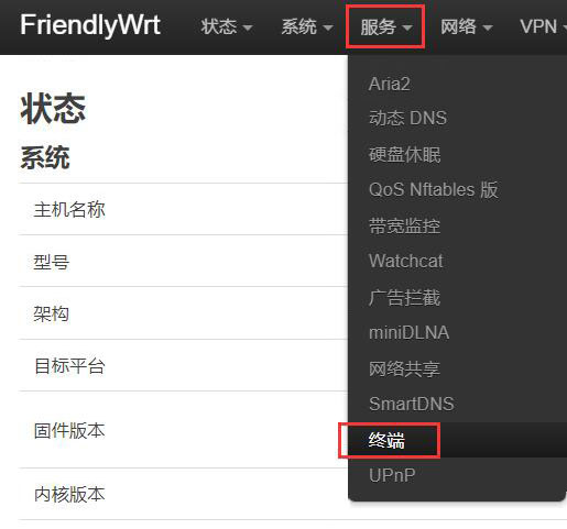
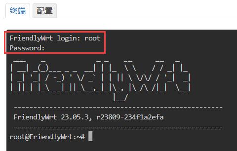
进入“服务 - 终端”,登录终端,默认用户名<code>root</code>,密码<code>password</code>: | |||
Navigate to Services - Terminal", log in to the terminal with the default username: <code>root</code> and password: <code>password</code>: | |||
http://www.mcuzone.com/wiki/4001_Friendly_NanoPi_R3S/4001_Friendly_NanoPi_R3S_49.jpg | http://www.mcuzone.com/wiki/4001_Friendly_NanoPi_R3S/4001_Friendly_NanoPi_R3S_49.jpg | ||
| 第26行: | 第30行: | ||
http://www.mcuzone.com/wiki/4001_Friendly_NanoPi_R3S/4001_Friendly_NanoPi_R3S_46.jpg | http://www.mcuzone.com/wiki/4001_Friendly_NanoPi_R3S/4001_Friendly_NanoPi_R3S_46.jpg | ||
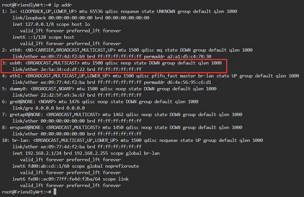
Execute <code>ip addr</code>, and the result is as follows: | |||
http://www.mcuzone.com/wiki/4001_Friendly_NanoPi_R3S/4001_Friendly_NanoPi_R3S_36.jpg | http://www.mcuzone.com/wiki/4001_Friendly_NanoPi_R3S/4001_Friendly_NanoPi_R3S_36.jpg | ||
You can see `usb0`, which is our CM4 Qualcomm 4G LTE module. This indicates that the system has recognized the 4G module, but it has not yet obtained an IP address. | |||
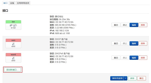
To use the 4G module for internet access, you need to add a 4G interface. The steps are as follows: | |||
进入“网络 - 接口”,点击“添加新接口”: | 进入“网络 - 接口”,点击“添加新接口”: | ||
Navigate to "Network - Interfaces," and click on "Add New Interface": | |||
http://www.mcuzone.com/wiki/4001_Friendly_NanoPi_R3S/4001_Friendly_NanoPi_R3S_37.jpg | http://www.mcuzone.com/wiki/4001_Friendly_NanoPi_R3S/4001_Friendly_NanoPi_R3S_37.jpg | ||
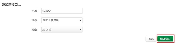
按下图进行配置(“名称”可以自定义),设备选择“usb0”,然后点击“创建接口”: | 按下图进行配置(“名称”可以自定义),设备选择“usb0”,然后点击“创建接口”: | ||
Configure as shown in the figure below (the "Name" can be customized), select "usb0" for the device, and then click "Create Interface": | |||
http://www.mcuzone.com/wiki/4001_Friendly_NanoPi_R3S/4001_Friendly_NanoPi_R3S_38.jpg | http://www.mcuzone.com/wiki/4001_Friendly_NanoPi_R3S/4001_Friendly_NanoPi_R3S_38.jpg | ||
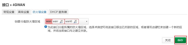
点击“防火墙设置”,在“创建/分配防火墙区域”中,选择wan,然后点击“保存”: | 点击“防火墙设置”,在“创建/分配防火墙区域”中,选择wan,然后点击“保存”: | ||
Click on "Firewall Settings", in the "Create/Assign Firewall Zones" section, select "WAN", and then click "Save": | |||
http://www.mcuzone.com/wiki/4001_Friendly_NanoPi_R3S/4001_Friendly_NanoPi_R3S_39.jpg | http://www.mcuzone.com/wiki/4001_Friendly_NanoPi_R3S/4001_Friendly_NanoPi_R3S_39.jpg | ||
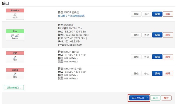
自动返回“接口”页面,点击“保存并应用”: | 自动返回“接口”页面,点击“保存并应用”: | ||
It automatically returns to the "Interface" page, then click "Save and Apply": | |||
http://www.mcuzone.com/wiki/4001_Friendly_NanoPi_R3S/4001_Friendly_NanoPi_R3S_40.jpg | http://www.mcuzone.com/wiki/4001_Friendly_NanoPi_R3S/4001_Friendly_NanoPi_R3S_40.jpg | ||
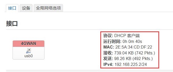
稍等片刻,我们可以看到4G模块已经获得了IP地址: | 稍等片刻,我们可以看到4G模块已经获得了IP地址: | ||
Wait for a moment, and we can see that the 4G module has obtained an IP address: | |||
http://www.mcuzone.com/wiki/4001_Friendly_NanoPi_R3S/4001_Friendly_NanoPi_R3S_41.jpg | http://www.mcuzone.com/wiki/4001_Friendly_NanoPi_R3S/4001_Friendly_NanoPi_R3S_41.jpg | ||
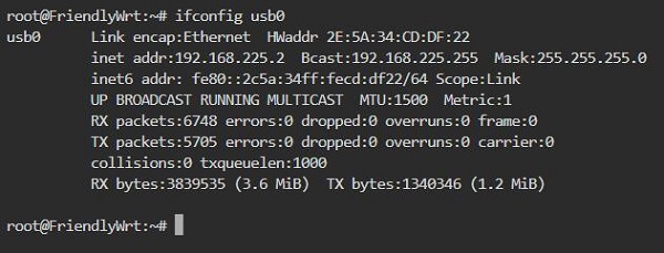
Back in the terminal, execute <code>ifconfig usb0</code> to check the network parameters of the 4G module: | |||
http://www.mcuzone.com/wiki/4001_Friendly_NanoPi_R3S/4001_Friendly_NanoPi_R3S_42.jpg | http://www.mcuzone.com/wiki/4001_Friendly_NanoPi_R3S/4001_Friendly_NanoPi_R3S_42.jpg | ||
A successful ping to the domain indicates that the 4G module is now able to browse the internet normally: | |||
http://www.mcuzone.com/wiki/4001_Friendly_NanoPi_R3S/4001_Friendly_NanoPi_R3S_43.jpg | http://www.mcuzone.com/wiki/4001_Friendly_NanoPi_R3S/4001_Friendly_NanoPi_R3S_43.jpg | ||
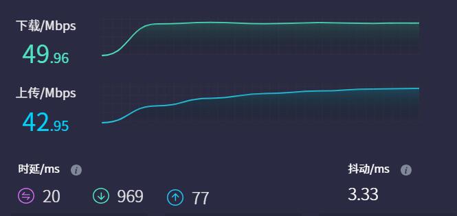
4G Module internet speed test: | |||
http://www.mcuzone.com/wiki/4001_Friendly_NanoPi_R3S/4001_Friendly_NanoPi_R3S_02.jpg | http://www.mcuzone.com/wiki/4001_Friendly_NanoPi_R3S/4001_Friendly_NanoPi_R3S_02.jpg | ||
''''' | '''''Note: Network speed testing is affected by the network environment and the testing method. The speed provided here is for reference only, please refer to the actual speed for accurate information.''''' | ||
=== 2.2 R3S外扩USB网卡 === | === 2.2 R3S外扩USB网卡 === | ||
2024年12月17日 (二) 11:49的版本
Keywords
FriendlyElec NanoPi R3S、RK3566、4G LTE、FriendlyWrt、OpenWrt、Ubuntu
I. Introduction
The 4G module for the R3S is a 4G LTE kit designed specifically for the FriendlyElec NanoPi R3S development board. It is based on our CM4 4G mini (Qualcomm 4G LTE) module, around which we have designed a 4G carrier board for the R3S along with a matching 3D-printed base to compose the set. The 3D printed base is designed to replace the R3S enclosure base and incorporates an integrated 4G antenna. The 4G module is supported out-of-the-box by the official Friendly firmware, with automatic detection and no need for additional driver installation.
The 4G module is a USB device that connects to the USB port of the R3S. For customers who have purchased an integrated kit that includes both a 4G module and an R3S from our company, we can assist with modifications if required. The modification involves transforming the USB cable of the 4G module to be fully internal, eliminating the need for a USB adapter board. However, after this modification, the USB port on the R3S will no longer be able to connect to any other USB devices.


II. Work with FriendlyWrt
The R3S development board comes in two versions: one without eMMC (which requires the system to be booted from a TF card), and another with eMMC (which allows the system to be booted either from the eMMC or from a TF card). All demonstrations in this document use the version that boots the system from a TF card. Different boot methods require corresponding different firmware packages. Please ensure that you match the correct firmware package to your boot method.
The version of the FriendlyElec system we tested: rk3566-sd-ubuntu-noble-core-6.1-arm64-20241114.img.gz
The 4G module is used as a WAN port in the FriendlyWrt system. Connect the R3S's LAN port to the PC's network port using an Ethernet cable. Open a web browser on the PC and navigate to 192.168.2.1 to log in to the FriendlyWrt system backend page (the default username is root and the password is password).
2.1 Test 4G module
进入“服务 - 终端”,登录终端,默认用户名root,密码password:
Navigate to Services - Terminal", log in to the terminal with the default username: root and password: password:
Execute ip addr, and the result is as follows:
You can see `usb0`, which is our CM4 Qualcomm 4G LTE module. This indicates that the system has recognized the 4G module, but it has not yet obtained an IP address.
To use the 4G module for internet access, you need to add a 4G interface. The steps are as follows:
进入“网络 - 接口”,点击“添加新接口”:
Navigate to "Network - Interfaces," and click on "Add New Interface":
按下图进行配置(“名称”可以自定义),设备选择“usb0”,然后点击“创建接口”:
Configure as shown in the figure below (the "Name" can be customized), select "usb0" for the device, and then click "Create Interface":
点击“防火墙设置”,在“创建/分配防火墙区域”中,选择wan,然后点击“保存”:
Click on "Firewall Settings", in the "Create/Assign Firewall Zones" section, select "WAN", and then click "Save":
自动返回“接口”页面,点击“保存并应用”:
It automatically returns to the "Interface" page, then click "Save and Apply":
稍等片刻,我们可以看到4G模块已经获得了IP地址:
Wait for a moment, and we can see that the 4G module has obtained an IP address:
Back in the terminal, execute ifconfig usb0 to check the network parameters of the 4G module:
A successful ping to the domain indicates that the 4G module is now able to browse the internet normally:

4G Module internet speed test:
Note: Network speed testing is affected by the network environment and the testing method. The speed provided here is for reference only, please refer to the actual speed for accurate information.
2.2 R3S外扩USB网卡
R3S自带两路以太网,如需第三路以太网,可以通过USB3.0口来扩展,但是此时将无法使用4G。我司测试了R3S可以支持RTL8153的USB有线网卡,可以作为第二个LAN口使用。操作如下:
先不接USB有线网卡,系统正常启动,登录后台页面。
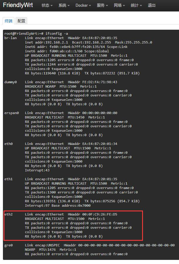
再插入USB有线网卡,稍等片刻,等在终端中执行ifconfig -a后出现eth2即可:
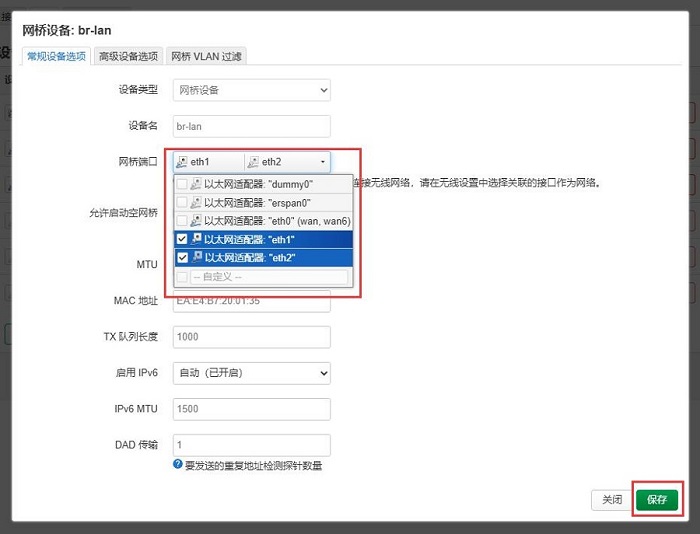
然后进入”网络 - 接口 - 设备“,点击br-lan后面的”配置...“:
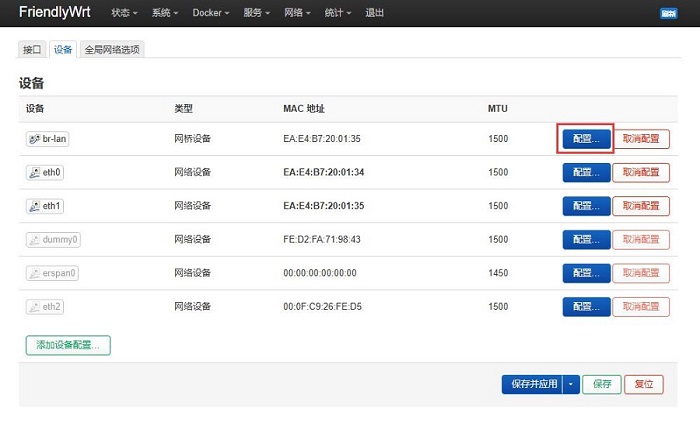
点击”网桥接口“后面的下拉箭头,将eth1和eth2都选中,然后按”保存“:
保存后返回上一层页面,按”保存并应用“:
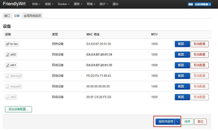
这样就设置了新增的USB有线网卡为LAN口,同时原来自带的LAN口也可以正常使用。
2.3 R3S外扩USB WiFi
R3S只有一路USB口,此USB口可以外扩USB WiFi,此时将无法使用4G。以外置MT7662 USB无线网卡为例:


注:通过无线网卡上网不稳定,有可能会出现找不到AP的问题。
2.4 FriendlyWrt的其他操作
2.4.1 Adblock

2.4.2 统计
如温控统计、处理器统计等:


三、Ubuntu系统的测试
R3S开发板有不带eMMC版本(需要从TF卡启动系统),也有带eMMC版本(可以从eMMC启动系统,也可以从TF卡启动系统),此文的演示均用从TF卡启动系统;不同的启动方式,对应的烧写包文件不一样,注意匹配即可。
3.1 测试4G模块
将Ubuntu系统(命令行版本,无图形化桌面)烧写进TF卡。
我们测试的友善官方烧写包版本:rk3566-sd-ubuntu-noble-core-6.1-arm64-20241114.img.gz
用网线将R3S的LAN口接上级路由器,然后PC连接同一个上级路由器,插入已安装SIM卡4G模块和烧好系统的TF卡。系统启动后,通过路由器的后台,查看R3S的ip地址,本文档中系统所获得的地址为:192.168.8.35。
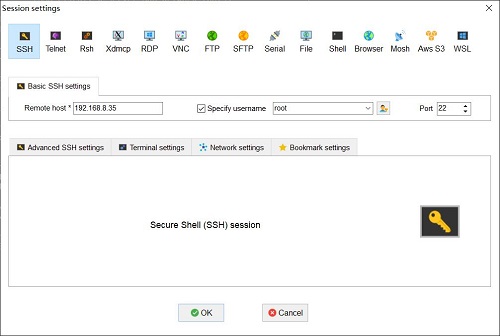
PC上下载安装终端软件MobaXterm,MobaXterm下载地址:
https://mobaxterm.mobatek.net/download-home-edition.html
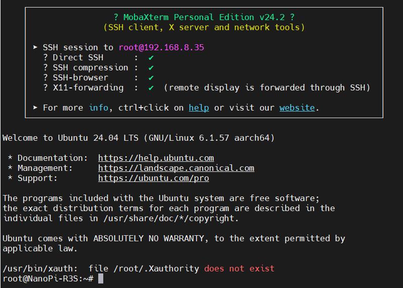
使用MobaXterm软件,通过SSH连接系统(用户名root,密码fa):
执行ifconfig -a,查看网络参数如下:

eth0是R3S的WAN口,没有接网线,所以没有IP地址;
eth1是R3S的LAN口,接上游路由器,已经正确获得了ip地址;
usb0是4G模块,已经正确获得了ip地址。
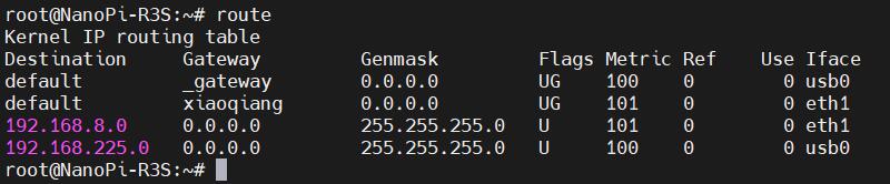
执行route,查看路由表,usb0排在第一位,因此此时是通过4G模块上网:
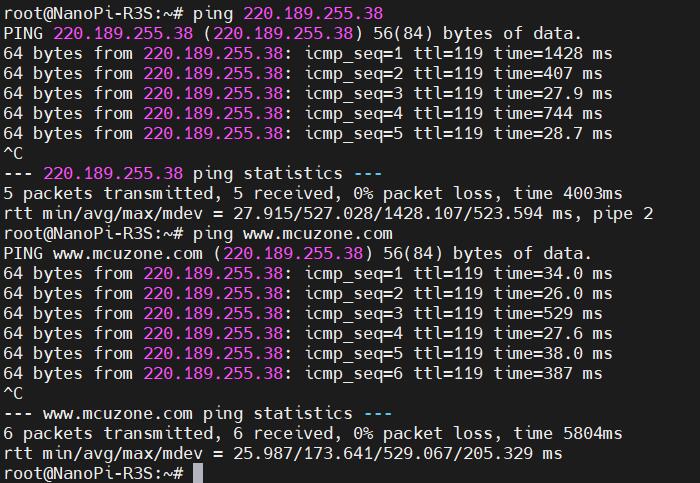
此时我们ping IP和域名,均成功,说明4G模块工作正常:
3.2 网络优先级的修改
R3S的Ubuntu系统,默认情况下,优先通过4G网络上网。
如果要优先使用有线网络上网的话,可以运行命令:
sudo ip route del default && sudo route add -net default netmask 0.0.0.0 gw 192.168.8.1
这两条命令(以“&&”分隔)的解释:
sudo ip route del default:删除路由表中的默认路由;
sudo route add -net default netmask 0.0.0.0 gw 192.168.8.1:添加有线网络的网关为新的默认路由(网关地址以实际为准)。
执行完毕后,再执行route,查看路由表,目前的默认路由为有线网络的网关(eth1排第一位):
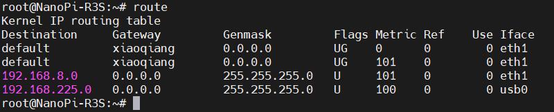
这样网络就默认走有线网络了,如果需要改回默认走4G网络,请运行:
sudo ip route del default && sudo route add -net default netmask 0.0.0.0 gw 192.168.225.1
或者重启系统即可。
其中192.168.225.1为4G模组的默认网关,请以实际为准。
注意,重启后路由表还是会恢复原状,所以如果重启后要网络继续默认走有线网络/无线网络,需要再执行一次sudo ip route del default && sudo route add -net default netmask 0.0.0.0 gw 192.168.8.1。
3.3 AT命令操作
先安装usbutils:
apt install usbutils
使用lsusb查看USB设备,红框处即为4G模组:
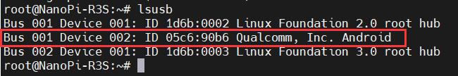
本模块的id为05c6 90b6,记录下这个值。
使用下列命令打开ttyUSB串口,其中echo后面的值就是之前记录的ID值:
modprobe option
sh -c 'echo 05c6 90b6 > /sys/bus/usb-serial/drivers/option1/new_id'
执行上述两条命令之后执行:
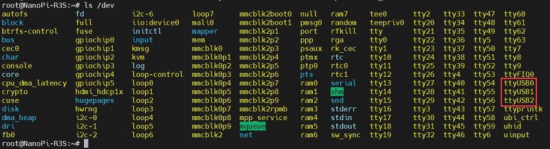
ls /dev
此时应该能看到dev设备下有ttyUSB0-2三个设备:
安装串口软件minicom:
apt install minicom
通过minicom打开AT命令串口:
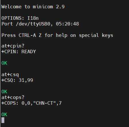
minicom -D /dev/ttyUSB0
(注意,使用哪个串口,应以在进入此串口后,可输入运行AT命令,显示不乱码,不乱跳结果为准。)
如果需要查看回显,请键入命令:ate1,然后回车,继续键入其它命令,回车可以看到结果。
常用AT命令:
1. 检查SIM卡是否识别到:
at+cpin?
返回ready表示卡已识别,返回error要检查硬件
2. 检查天线信号质量:
at+csq
返回值在26-31表示信号OK,信号满格31;返回值在20-25表示信号勉勉强强;返回值在20以下表示信号比较糟糕或者天线没接
3. 检查注网情况:
at+cops?
正常应该返回运营商代码和7,7代表4G。
注意,以上命令只有at+csq不要加问号,另外两条命令需要加问号。
4. 查看4G模块的IMEI码:
at+cgsn
5. 重启4G模块(有时候如果重插SIM卡,热插拔不一定管用,可以用这个reset命令来复位模块):
at+reset
6. 关闭射频:
at+cfun=0
开启射频:
at+cfun=1
上述两条命令成对使用,可以在不重启4G模组的情况下让模组重新注网。
3.4 修改4G模组的IP地址
如果出厂默认的4G IP地址和用户使用的IP地址有冲突,或有修改IP地址的需求,则将4G模块的IP改为直接获取公网IP即可,请执行AT命令:
设置IP为公网:AT+GTIPPASS=1
设置IP为内网:AT+GTIPPASS=0
查询当前IP为公网还是内网:AT+GTIPPASS?
修改IP完毕后需要断电重启才能生效。
四、总结
此处仅介绍4G模块基于NanoPi R3S的操作,不涉及到NanoPi R3S开发板自身的操作及软件系统,关于NanoPi R3S开发板资料,请前往友善官网查阅:
https://wiki.friendlyelec.com/wiki/index.php/NanoPi_R3S/zh
联系我们


 QQ:8204136
电话:13957118045
如本页面有任何疏漏、错误或者侵权,请通过上述途径联系我们,谢谢!
Copyright 2004-2025 野芯科技