1003 RPi0 4G Cat1-Hub EN:修订间差异
| 第18行: | 第18行: | ||
3. A 4G CAT1 module, can option the GPS functionality. '''''Users in other countries can also select other CAT1 modules that match their frequency bands.''''' | 3. A 4G CAT1 module, can option the GPS functionality. '''''Users in other countries can also select other CAT1 modules that match their frequency bands.''''' | ||
4. A Nano SIM card slot (located on the reverse side). '''''Note: | 4. A Nano SIM card slot (located on the reverse side). '''''Note: SIM card hot-swapping is not supportted.''''' | ||
5. A first-generation IPEX connector, which can be used with external 4G FPC or rod antennas. | 5. A first-generation IPEX connector, which can be used with external 4G FPC or rod antennas. | ||
2024年11月15日 (五) 09:07的最新版本
Keywords
Raspberry Pi Zero, Zero 2W, Cat1 4G LTE, USB2.0, USB Type-C, USB HUB, Nano SIM, RPi-Connect, Remote connection
I. Introduction
The Raspberry Pi Zero series (including the Zero, Zero W/H, and Zero 2W) is a highly cost-effective embedded system platform, known for its small size, low power consumption, and acceptable performance, making it suitable for many lightweight application scenarios. Although the Zero series is compact, it reserves a large number of expansion interfaces. Especially on the backside of the board, gold-plated test points for USB and power are brought out. We can use these sets of USB and power test points to expand various types of peripherals.
This expansion board is essentially a USB hub that connects to the Zero's USB port via pogo pins. It expands four USB ports via USB, with one USB port converted to a 4G Cat1 module, and three USB 2.0-A host ports.
4G Cat1 is a high-cost-performance module aimed at medium-speed IoT applications around 10 Mbps. The 10 Mbps downlink and 5 Mbps uplink speeds can satisfy the majority of connectivity and transmission requirements. The CAT1 module is driver-free and automatically recognized in the Raspberry Pi OS, Ubuntu system, and OpenWrt system, making it easy to use.
II. Hardware Spec
1. This board connects to the Raspberry Pi Zero's USB port and power contacts via four pogo pins for both power supply and communication.
2. A USB-C power port, which functions are the same as the power port on the Raspberry Pi Zero itself. You can choose to use either one, but not both simultaneously.
3. A 4G CAT1 module, can option the GPS functionality. Users in other countries can also select other CAT1 modules that match their frequency bands.
4. A Nano SIM card slot (located on the reverse side). Note: SIM card hot-swapping is not supportted.
5. A first-generation IPEX connector, which can be used with external 4G FPC or rod antennas.
6. Three USB 2.0 Type-C host, with each USB port capable of supplying 1A of power (Note: the Raspberry Pi Zero's own OTG functionality will no longer be usable, and the Zero's own micro USB port cannot be used to connect any USB devices, otherwise, this expansion board will not function properly).
7. Have debugging UART and the AT main UART, both with 3.3V voltage levels.
8. Three LEDs:
- one is the power indicator for the expansion board.
- one is the power indicator for the 4G module.
- one is the NET led: a 1.8-second on and 0.2-second off cycle indicates successful network registration, while a 1.8-second off and 0.2-second on cycle indicates that the device has not registered with the network, and you should check the SIM card and antenna.
9. A BOOT button and a reset button.
10. Sizes: 65*30*6.6mm, with four M2.5 mounting holes.
11. An optional 3D printed base is available to protect the circuit board.
12. The circuit board uses an ENIG (Electroless Nickel Immersion Gold) process, is produced without lead, and the PCB has received UL and RoHS certifications, with a fire protection rating of 94V-0.


III. Work with Raspberry Pi OS
The Raspberry Pi OS used in this document is: 2024-07-04-raspios-bookworm-arm64.img.xz(Raspberry Pi OS with desktop).
(If you are using the Raspberry Pi Zero (1st generation) series boards, they only support 32-bit systems. Please be sure to download the correct version.)
You can download the Raspberry Pi OS in:
https://www.raspberrypi.com/software/operating-systems/#raspberry-pi-os-64-bit
☆ 3.1 View hardware devices
3.1.1 Hardware connection
This expansion board features four USB Type-C ports. One of these USB Type-C ports is labeled as PWR on the silkscreen on the back, indicating it is the power input USB Type-C port. The remaining three USB Type-C ports are HOST ports, which can be used to connect USB devices such as keyboards, mice, and USB drives, among other peripherals. Above the 4G module, there are two antenna connectors; one is for the 4G signal antenna, and the other is for the GPS signal antenna. All peripherals are driver-free, meaning they are plug-and-play.
The Raspberry Pi Zero board is fixed above the expansion board using four screws. Please pay attention to the installation direction and ensure that the pogo pins on the expansion board align with the corresponding contacts on the Zero board. Connect the HDMI cable and power supply, and note that the Zero's micro USB port should not be connected to any devices.
3.1.2 View USB devices
Open the terminal in Raspberry Pi OS and enter the commandlsusb, as shown in the image below:

The system has detected the USB hub and the 4G module:
Device 002: External USB Hub;
Device 003: 4G module;
Device 004: USB2.0 Type-C interface;
If the system stop at the Raspberry Pi logo and fails to boot:
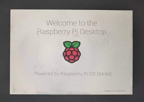
or if after booting, the keyboard, mouse, and 4G module cannot be used,
please carefully check whether the pogo pins are aligned with the gold-plated contacts. Additionally, on the PC, open the config.txt file located in the root directory of the TF card to check the USB initialization script.
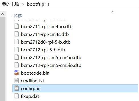
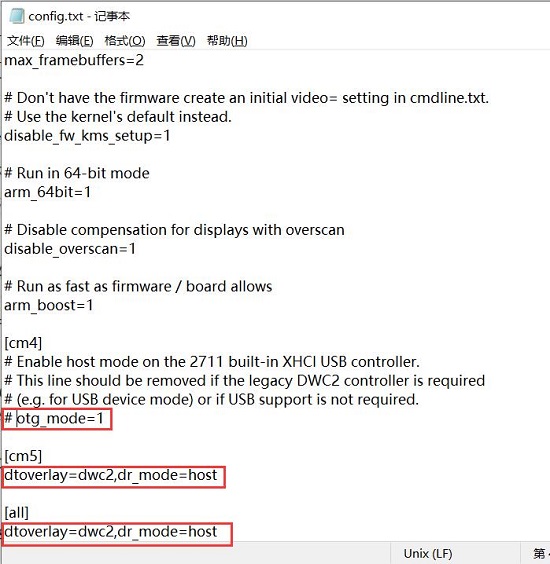
You need to confirm that the three red-boxed areas in the following image are all configured completely. If not, please manually add the missing parts and save the file:
# otg_mode=1 (It is recommended to comment out as follow)
dtoverlay=dwc2,dr_mode=host (These two areas must be ensured to be included.)
3.1.3 View 4G module
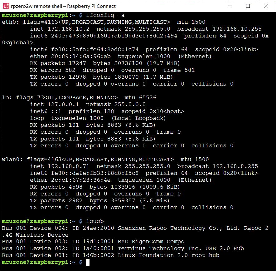
Open the terminal in Raspberry Pi OS and enter the commandifconfig -a, as shown in the image below:
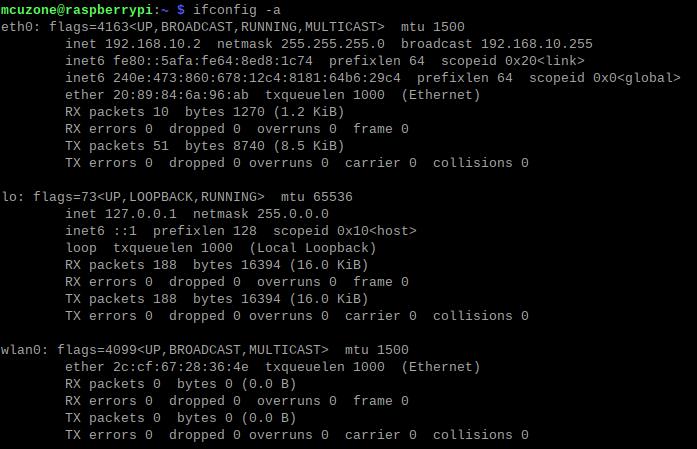
You can see that eth0 as the 4G Cat1 (which has automatically connected, with the default IP address in the above example being 192.168.10.2), and wlan0 as the wireless network card that comes with the Zero 2W.
☆ 3.2 Test 4G module
3.2.1 Operations on 4G when the system has not set up WiFi
When the Raspberry Pi OS boots, WiFi is enabled by default, but it is not connected to any access point (meaning no WiFi account and password are set in the system). So when connecting to the internet via the 4G module, we can perform a ping operation:
Ping the IP should correctly display as follows:

Ping the domain name should correctly display as follows:

This indicates that the 4G connection is normal.
Solution for ping domain error:
If you encounter a ping domain error, as shown in the image:

This indicates that the DNS server settings for the 4G module are incorrect. Let's modify the DNS server settings:
First, we need to connect to WiFi:
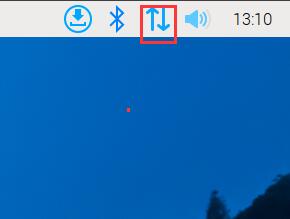
Click on the network icon in the upper right corner and select the AP you want to connect to:
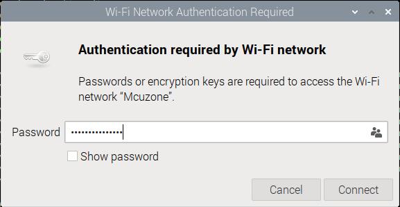
Enter the password (if there is one), and then click "Connect":
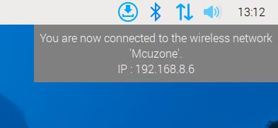
After a successful connection, you can obtain the IP address of the router and access the internet normally:
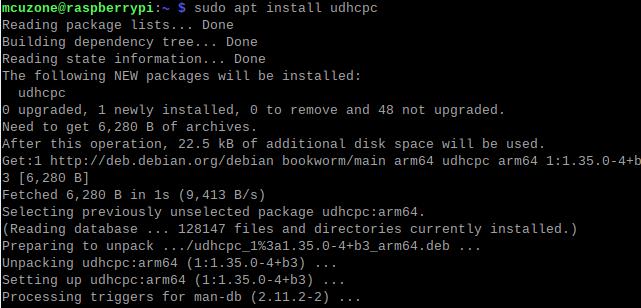
Install the DNS server switching software udhcpc:
sudo apt install udhcpc
After installation, use the following command to switch the DNS server to the 4G module (in this case, eth0 represents the 4G module; the name may differ depending on the software and hardware platform):
sudo udhcpc -i eth0
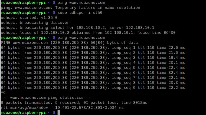
This way, you achieve normal internet browsing via 4G.
The method of switching DNS servers for 4G internet access will stop working after the system is restarted. If you want the DNS server to automatically switch to the 4G module each time the system starts, you can follow these steps:
Open rc-local service:
sudo systemctl enable --now rc-local
Use the following command to open rc.local:
sudo nano /etc/rc.local
Add the command you want to execute at startup above the line exit 0, and then save the file (in this example, eth0 represents the 4G module, but the name should match the actual interface identified on your system):
sleep 5 && sudo udhcpc -i eth0 && sleep 5 && sudo udhcpc -i eth0 && sleep 5 && sudo udhcpc -i eth0
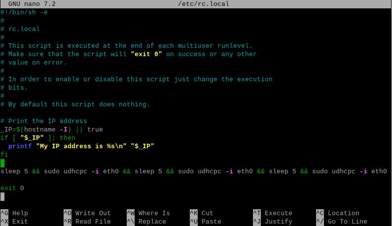
The sleep command is used to delay the execution of subsequent commands by a certain number of seconds. Since the 4G module needs some time to acquire an IP address, to prevent `udhcpc` from failing, it needs to be executed several times with a delay added between each execution. As a result, the 4G network becomes usable approximately 20 seconds after the system boots up.
3.2.2 The system has already been set up for WiFi connectivity, and the operations for the 4G connection
If your system was previously set up with WiFi, the Raspberry Pi Zero 2W will provide internet access via WiFi when used alone. When you install our expansion board, upon rebooting the system, it will prioritize using the 4G network for internet access. If you want to switch to WiFi, you can follow these steps:
Disable the 4G network connection:
sudo ifconfig eth0 down

Use udhcpc to switch the DNS server to the WiFi's DNS server.
sudo udhcpc -i wlan0

If you later want to switch back to browsing the internet using the 4G network, you can run:
sudo ifconfig eth0 up
sudo ifconfig wlan0 down
sudo udhcpc -i eth0
3.2.3 Access the 4G module via SSH over WiFi
If you want to enable SSH using the Raspberry Pi ZERO's WiFi to subsequently perform 4G operations on the Raspberry Pi, you need to set up the SSH service before flashing the system. For the steps, refer to this guide.
☆ 3.3 How to use AT commands and GPS
3.3.1 Open AT serial
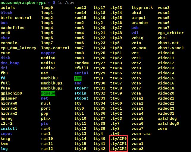
Execute the command in the SSH terminal:
ls /dev
You should be able to see three devices named ttyACM0, ttyACM1, and ttyACM2 under the dev directory:
Install minicom:
sudo apt-get install minicom

Open AT Command serial port by minicom:
sudo minicom -D /dev/ttyACM0
Note: When using a serial port, ensure that after entering this port, you can input and run AT commands without any garbled output or unexpected jumps in the results.
3.3.2 Execute AT commands
The following uses minicom as an example:
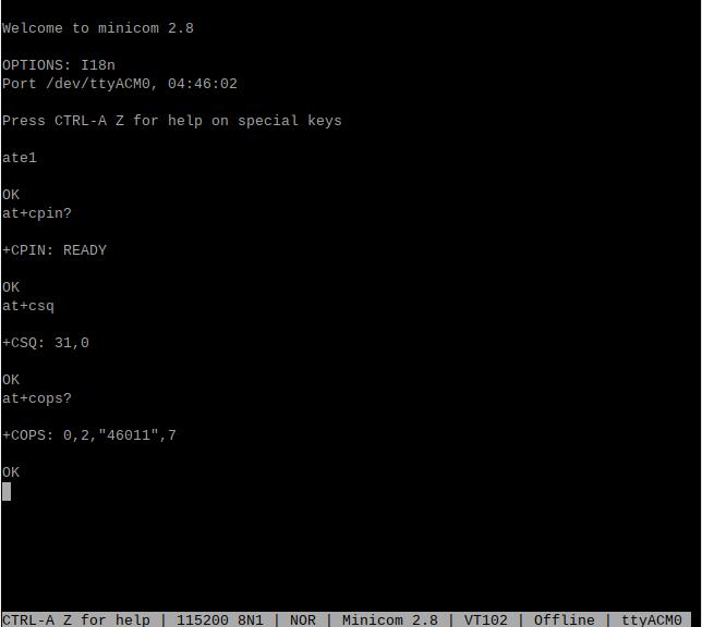
Then directly type the AT command and press Enter to see the result. If you need to view the echo, please type the command: ate1:
Use AT+CPIN? to check if the SIM card is properly inserted and recognized;
Use AT+CSQ to check the signal strength; the first value ranges from 0-31, and a value of 25 or above is considered good signal quality;
Use AT+COPS? to check the network registration status; the quotation marks contain the operator code, and the last digit represents the network mode, with 7 indicating 4G.
3.3.3 GPS Test (only for GPS version)
When using GPS, you need to connect a passive GPS antenna and ensure that the GPS antenna is extended outdoors.
Run minicom and open the ttyACM0 serial port:
sudo minicom -D /dev/ttyACM0
And execute:
AT+CGNSPWR=1 //Open GPS
AT+CGNSAID=31,1,1,1 //Enable location assistance positioning (the command will immediately return OK, and positioning will succeed in about 2-10 seconds based on signal strength).
AT+CGNSURC=1 //Setup automatic reporting of location information
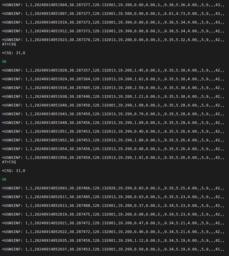
After running successfully, you will be able to see GPS information output from the serial port: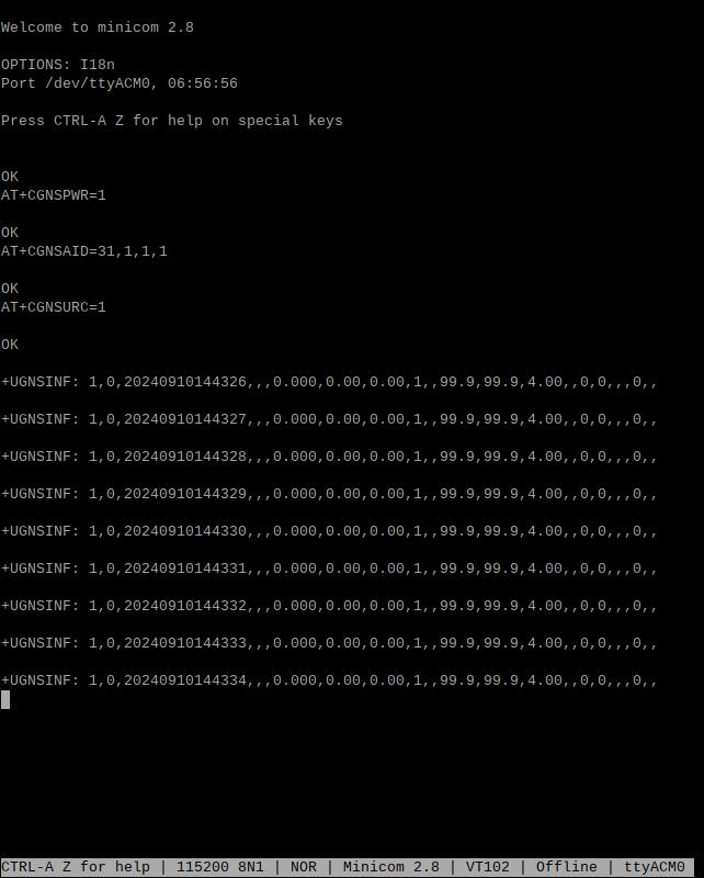
Wait for a moment, and the device will then be able to acquire its location.
IV. Work with Ubuntu system
Ubuntu system: Ubuntu Server 24.04 LTS. (The Raspberry Pi Zero 2W cannot use the Desktop version due to performance limitations.)
The image is: ubuntu-24.04-preinstalled-server-arm64+raspi.img.xz
You can download the Ubuntu system in:
https://ubuntu.com/download/raspberry-pi
(If using the first-generation Raspberry Pi Zero board, which only supports 32-bit systems, there may not be a suitable Ubuntu Server system available.)
4.1 Edit the initialization script
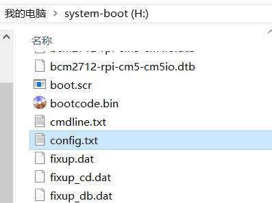
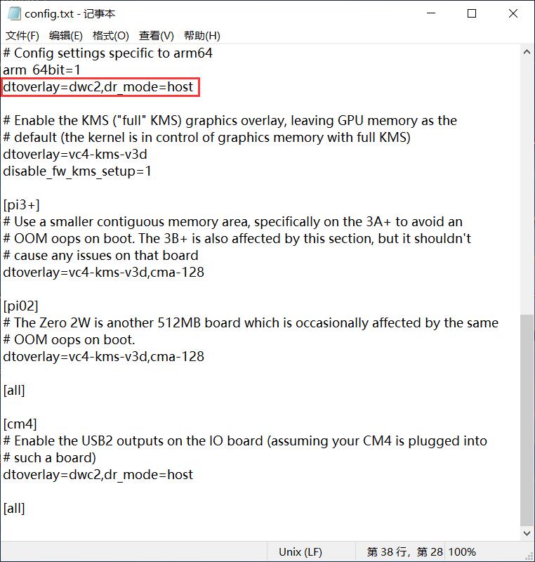
After flashing Ubuntu Server to the TF card, please open the config.txt file in the root directory of the system partition on your PC to check the USB initialization script. Ubuntu Server initializes the USB twice, and the first initialization does not configure it into host mode. You need to verify if the position indicated by the red box in the following diagram is fully configured. If it is not, please manually add the complete configuration:
dtoverlay=dwc2,dr_mode=host
4.2 Configure the username and password
Insert the TF card into the Zero 2W and boot the system. Upon the first boot, you will be prompted to log in. The username and password are both ubuntu. After logging in successfully, you will be prompted to change the password:

After modifying the password, you will automatically enter the system.
4.3 Configure the network
After the system boots, there is no network available, and setup is required before it can be used.
Note: the system does not integrate the ifconfig tool by default; only the ip command is available.
Execute ip addr to view and record the network interface name:

The second network interface (enx2089846a96ab) is the 4G module.
Then run the following command to open the network interface configuration file:
sudo nano /etc/netplan/50-cloud-init.yaml
Edit the network interface configuration file according to the image below:
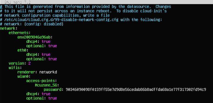
Save and exit, then restart.
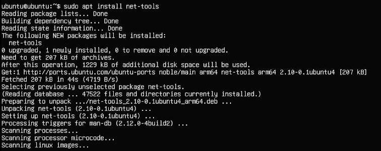
After restarting, you can connect to the network. Install the net-tools package for convenience:
sudo apt install net-tools
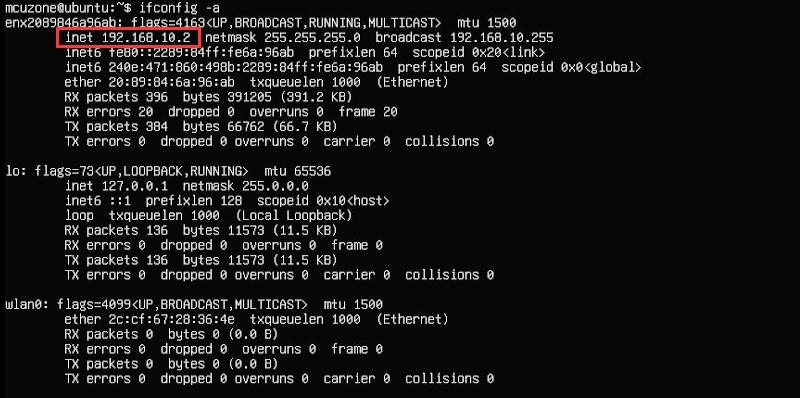
Run ifconfig -a to see that the 4G module has correctly obtained an IP address:
4.4 Test AT commands
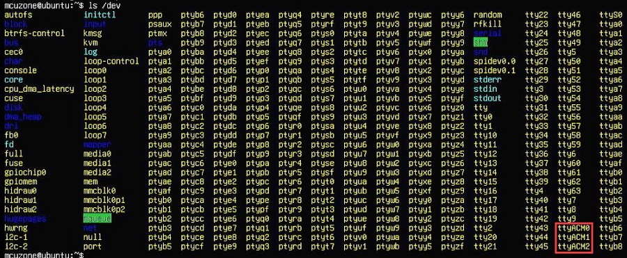
Execute command:
ls /dev
You should be able to see three devices named ttyACM0, ttyACM1, and ttyACM2 under the dev directory:
Install minicom:
sudo apt-get install minicom

Open AT Command serial port by minicom:
sudo minicom -D /dev/ttyACM0
Note: When using a serial port, ensure that after entering this port, you can input and run AT commands without any garbled output or unexpected jumps in the results.
The following uses minicom as an example:
Then directly type the AT command and press Enter to see the result. If you need to view the echo, please type the command: ate1:
Use AT+CPIN? to check if the SIM card is properly inserted and recognized;
Use AT+CSQ to check the signal strength; the first value ranges from 0-31, and a value of 25 or above is considered good signal quality;
Use AT+COPS? to check the network registration status; the quotation marks contain the operator code, and the last digit represents the network mode, with 7 indicating 4G.
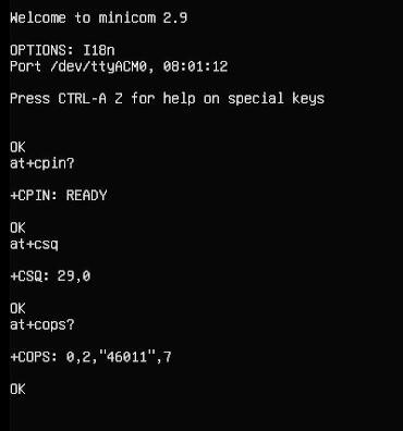
Common AT commands:
1) Check if the SIM card is detected:
at+cpin?
Return ready to indicate the card has been recognized, if return error, you need to check the hardware.
2) Check antenna signal quality:
at+csq
Return values between 26 and 31 indicate a good signal, with 31 representing a full signal strength; return values between 20 and 25 indicate a barely acceptable signal; return values below 20 indicate a poor signal or that the antenna might not be connected.
3) Check network registration status:
at+cops?
Normally, it should return the network supporter's code: 7, where 7 represents 4G.
Note: The above command at+csq should not include a question mark, while the other two commands require a question mark.
4) View the SIM card's IMEI code:
at+cgsn
5) Reset 4G module (Sometimes, if you reinsert the SIM card, hot swapping may not work; in such cases, you can use this reset command to reset the module.):
at+reset
6) Disable radio frequency:
at+cfun=0
Enable radio frequency:
at+cfun=1
The two commands mentioned above can be used in pairs to allow the module to re-register with the network without restarting the 4G module.
V. (Remote Connection) Raspberry Pi Connect to access your Raspberry Pi remotely
RPi-Connect provides a service for secure access to your Raspberry Pi from anywhere. With this service, combined with the Zero_Cat1_4G Cat1-Hub version, you can still remotely access your Raspberry Pi even when outdoors without a Wi-Fi network. Note: To use this service, Bookworm or a newer system must be running. Additionally, only the Raspberry Pi 5, 4, or 400 can use screen sharing. The Zero 2W can only use Remote Shell. The following demonstrates how to configure the remote connection service.
5.1 Apply for a Raspberry Pi ID
If you already have a Raspberry Pi ID, please log in directly. If not, please follow the steps below to apply.
Open the website at https://id.raspberrypi.com/, and enter the email address and password you wish to use:

After creating the account, you need to verify it by entering your email:
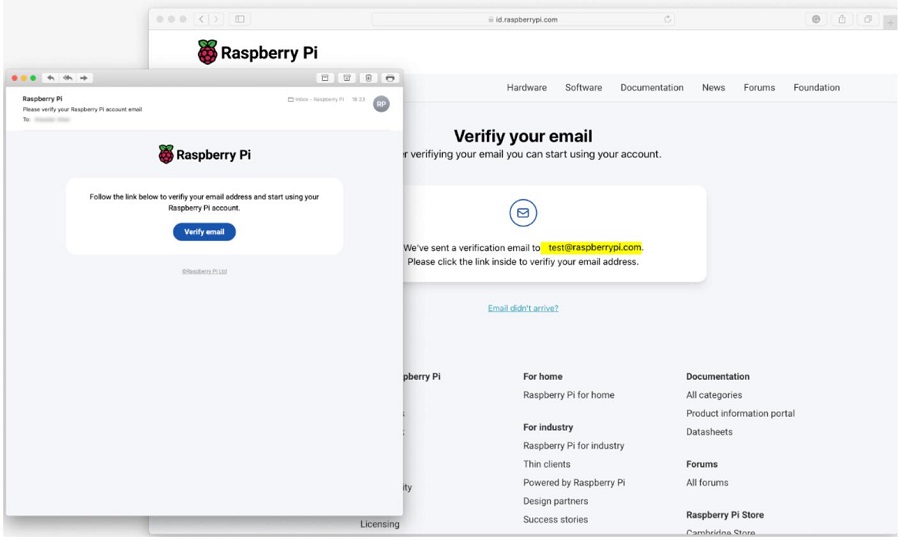
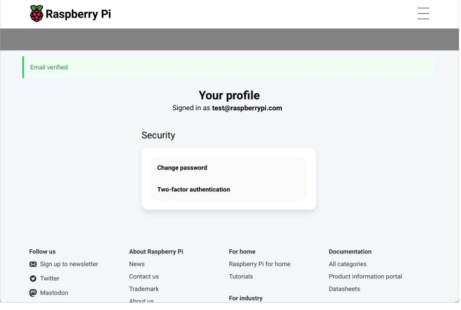
After verification is complete, the ID can be used.
5.2 Install Remote Service
Open the SSH terminal and install the Raspberry Pi Connect software. If the installation command indicates that it is already installed, then no additional installation is necessary:
sudo apt install rpi-connect
After installation, we enter loginctl enable-linger in the terminal to ensure that the remote service is automatically enabled each time the system restarts:

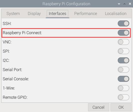
Restart the system. In the graphical interface, select the items in the order shown in the following image to ensure that Raspberry Pi Connect is turned on:
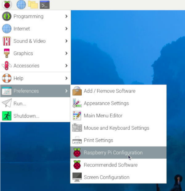
Then enter the following in the Raspberry Pi terminal:
rpi-connect signin

Now, a URL is displayed, as shown in the image above. Open this URL in a browser (it is recommended to use another computer, as the Zero series can be very slow when opening a browser due to hardware limitations).
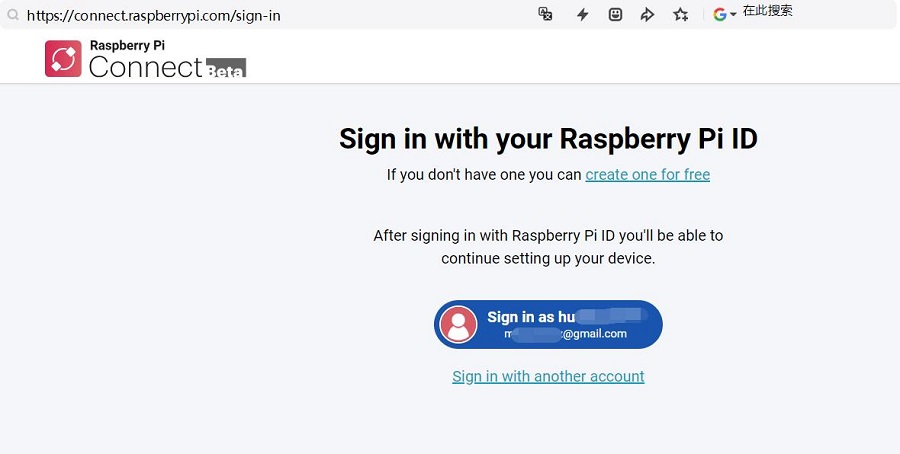
Click on "Sign in" and follow the prompts to bind the device. First, you need to set the device name:
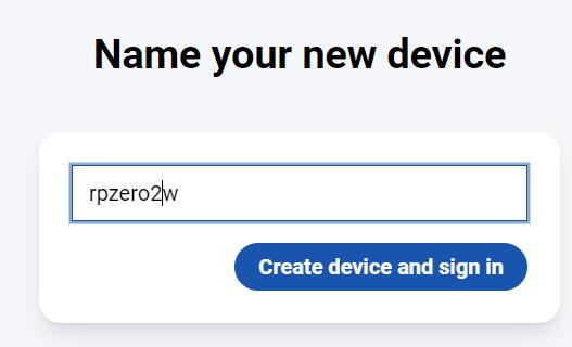
Click "Create device and sign in":
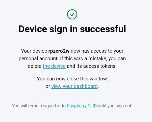
This completes the binding process, and there will also be a successful message displayed in the terminal:

5.3 Use remote control
On your PC, open: https://connect.raspberrypi.com/devices

The Zero 2W device just added only shows "Remote shell", indicating that this device can only be controlled through a remote command-line interface.
Click on "Connect" to open the remote command-line interface, where you can then enter commands:
Contact Us
Email: mcuzone@vip.qq.com
Tel: +86(0)13957118045
If there are any omissions, errors, or infringements on this page, please contact us through the above methods. Thank you!
Copyright 2004-2024 Wildchip


 QQ:8204136