1003 RPi0 4G Cat1-Hub EN:修订间差异
(创建页面,内容为“== '''关键词''' == 树莓派 Zero、Zero 2W、Cat1 4G LTE、USB2.0、USB Type-C、USB HUB 集线器、Nano SIM、eSIM、RPi-Connect、远程连接 == '''一、简介''' == 树莓派Zero系列(包括Zero、Zero W(H)以及Zero 2W)是一款具备极高性价比的嵌入式系统平台,尺寸小巧功耗较低性能尚可,适合很多轻量型应用场景。Zero系列虽然小巧,但预留了非常多的扩展接口,特别是板子反面引出了USB…”) |
无编辑摘要 |
||
| 第1行: | 第1行: | ||
[[1003 RPi0 4G Cat1-Hub|切换语言为中文]] | |||
== ''' | == '''Keywords''' == | ||
Raspberry Pi Zero, Zero 2W, Cat1 4G LTE, USB2.0, USB Type-C, USB HUB, Nano SIM, RPi-Connect, Remote connection | |||
== '''I. Introduction''' == | |||
The Raspberry Pi Zero series (including the Zero, Zero W/H, and Zero 2W) is a highly cost-effective embedded system platform, known for its small size, low power consumption, and acceptable performance, making it suitable for many lightweight application scenarios. Although the Zero series is compact, it reserves a large number of expansion interfaces. Especially on the backside of the board, gold-plated test points for USB and power are brought out. We can use these sets of USB and power test points to expand various types of peripherals. | |||
4G | This expansion board is essentially a USB hub that connects to the Zero's USB port via pogo pins. It expands four USB ports via USB, with one USB port converted to a 4G Cat1 module, and three USB 2.0-A host ports. | ||
4G Cat1 is a high-cost-performance module aimed at medium-speed IoT applications around 10 Mbps. The 10 Mbps downlink and 5 Mbps uplink speeds can satisfy the majority of connectivity and transmission requirements. The CAT1 module is driver-free and automatically recognized in the Raspberry Pi OS, Ubuntu system, and OpenWrt system, making it easy to use. | |||
== '''II. Hardware Spec''' == | |||
1. This expansion board connects to the Raspberry Pi Zero's USB port and power contacts via four pogo pins for both power supply and communication. | |||
2. A USB-C power port is provided, which functions are the same as the power port on the Raspberry Pi Zero itself. You can choose to use either one, but not both simultaneously. | |||
3. The board includes a 4G CAT1 module, with an option for a 4G module that includes GPS functionality. Users in other countries can also select other CAT1 modules that match their frequency bands. | |||
4. Uses a Nano SIM card slot (located on the reverse side). Please refer to the silkscreen on the board for the direction in which the SIM card should be inserted. | |||
5. It uses a first-generation IPEX connector, which can be used with external 4G FPC or rod antennas. If the GPS version is selected, a passive GPS antenna is required, and the antenna must be placed outside the window to achieve positioning. | |||
6. The board features three USB 2.0 Type-C host interfaces, with each USB port capable of supplying 1A of power (Note: the Raspberry Pi Zero's own OTG functionality will no longer be usable, and the Zero's own micro USB port cannot be used to connect any USB devices, otherwise, this expansion board will not function properly). | |||
7. Reserve the debugging serial port and the AT main serial port, both with 3.3V voltage levels. | |||
8. There are three LED indicator lights; one is the power indicator for the expansion board, and another is the power indicator for the 4G module. The NET LED indicates the network status: a 1.8-second on and 0.2-second off cycle indicates successful network registration, while a 1.8-second off and 0.2-second on cycle indicates that the device has not registered with the network, and you should check the SIM card and antenna. | |||
9. The board features positions for the BOOT and reset buttons. | |||
10. Sizes: 66*30mm, with four M2.5 mounting holes, each with a height of 5mm. The board size is fully compatible with the Raspberry Pi Zero series boards. | |||
12. | 11. An optional 3D printed base is available to protect the circuit board. | ||
12. The circuit board uses an ENIG (Electroless Nickel Immersion Gold) process, is produced without lead, and the PCB has received UL and RoHS certifications, with a fire protection rating of 94V-0. | |||
http://www.mcuzone.com/wiki/1003_Zero_4G_Cat1-Hub/1003_Zero_4G_Cat1-Hub_24.jpg | http://www.mcuzone.com/wiki/1003_Zero_4G_Cat1-Hub/1003_Zero_4G_Cat1-Hub_24.jpg | ||
| 第40行: | 第42行: | ||
http://www.mcuzone.com/wiki/1003_Zero_4G_Cat1-Hub/1003_Zero_4G_Cat1-Hub_26.jpg | http://www.mcuzone.com/wiki/1003_Zero_4G_Cat1-Hub/1003_Zero_4G_Cat1-Hub_26.jpg | ||
== ''' | == '''III. System flashing''' == | ||
=== 3.1 | === 3.1 Overview === | ||
The hardware in this document is based on the Raspberry Pi Zero 2W. | |||
1. The Raspberry Pi OS used in this document is: 2024-07-04-raspios-bookworm-arm64.img.xz(Raspberry Pi OS with desktop). | |||
(If you are using the Raspberry Pi Zero (1st generation) series boards, they only support 32-bit systems. Please be sure to download the correct version.) | |||
You can download the Raspberry Pi OS in: | |||
https://www.raspberrypi.com/software/operating-systems/#raspberry-pi-os-64-bit | <nowiki>https://www.raspberrypi.com/software/operating-systems/#raspberry-pi-os-64-bit</nowiki> | ||
2)Ubuntu系统,Ubuntu Server 24.04 LTS,服务器版(树莓派Zero 2W因为性能关系不能用Desktop版),镜像为ubuntu-24.04-preinstalled-server-arm64+raspi.img.xz | 2)Ubuntu系统,Ubuntu Server 24.04 LTS,服务器版(树莓派Zero 2W因为性能关系不能用Desktop版),镜像为ubuntu-24.04-preinstalled-server-arm64+raspi.img.xz | ||
| 第59行: | 第61行: | ||
https://ubuntu.com/download/raspberry-pi | https://ubuntu.com/download/raspberry-pi | ||
2. Ubuntu system: Ubuntu Server 24.04 LTS. (The Raspberry Pi Zero 2W cannot use the Desktop version due to performance limitations.) | |||
The image is: ubuntu-24.04-preinstalled-server-arm64+raspi.img.xz | |||
You can download the Ubuntu system in: | |||
https://ubuntu.com/download/raspberry-pi | |||
(If using the first-generation Raspberry Pi Zero board, which only supports 32-bit systems, there may not be a suitable Ubuntu Server system available.) | |||
=== | === 3.2 Flash the OS image in TF card === | ||
[[0005 MPS2242 2280 2280P(Single SSD Expansion Board)#3.2 Boot from TF card|Click here to read the instructions for System flashing]] | |||
== | == '''IV. Work with Raspberry Pi OS''' == | ||
=== ☆ 4.1 View hardware devices === | |||
==== 4.1.2 | ==== 4.1.1 Hardware connection ==== | ||
This expansion board features four USB Type-C ports. One of these USB Type-C ports is labeled as PWR on the silkscreen on the back, indicating it is the power input USB Type-C port. The remaining three USB Type-C ports are HOST ports, which can be used to connect USB devices such as keyboards, mice, and USB drives, among other peripherals. Above the 4G module, there are two antenna connectors; one is for the 4G signal antenna, and the other is for the GPS signal antenna. All peripherals are driver-free, meaning they are plug-and-play. | |||
The Raspberry Pi Zero board is fixed above the expansion board using four screws. Please pay attention to the installation direction and ensure that the pogo pins on the expansion board align with the corresponding contacts on the Zero board. Connect the HDMI cable and power supply, and '''''note that the Zero's micro USB port should not be connected to any devices'''''. | |||
==== 4.1.2 View USB devices ==== | |||
Open the terminal in Raspberry Pi OS and enter the command<code>lsusb</code>, as shown in the image below: | |||
http://www.mcuzone.com/wiki/1003_Zero_4G_Cat1-Hub/1003_Zero_4G_Cat1-Hub_01.jpg | http://www.mcuzone.com/wiki/1003_Zero_4G_Cat1-Hub/1003_Zero_4G_Cat1-Hub_01.jpg | ||
The system has detected the USB hub and the 4G module: | |||
Device | Device 002: External USB Hub; | ||
Device | Device 003: 4G module; | ||
Device | Device 004: USB2.0 Type-C interface; | ||
If the system stop at the Raspberry Pi logo and fails to boot: | |||
http://www.mcuzone.com/wiki/0007_Zero_4G_Cat1/0007_Zero_4G_Cat1_58.jpg | http://www.mcuzone.com/wiki/0007_Zero_4G_Cat1/0007_Zero_4G_Cat1_58.jpg | ||
or if after booting, the keyboard, mouse, and 4G module cannot be used, | |||
please carefully check whether the pogo pins are aligned with the gold-plated contacts. Additionally, on the PC, open the <code>config.txt</code> file located in the root directory of the TF card to check the USB initialization script. | |||
http://www.mcuzone.com/wiki/0007_Zero_4G_Cat1/0007_Zero_4G_Cat1_41.jpg | http://www.mcuzone.com/wiki/0007_Zero_4G_Cat1/0007_Zero_4G_Cat1_41.jpg | ||
You need to confirm that the three red-boxed areas in the following image are all configured completely. If not, please manually add the missing parts and save the file: | |||
<code># otg_mode=1</code> | <code># otg_mode=1</code> (It is recommended to comment out as follow) | ||
<code>dtoverlay=dwc2,dr_mode=host</code> | <code>dtoverlay=dwc2,dr_mode=host</code> (These two areas must be ensured to be included.) | ||
http://www.mcuzone.com/wiki/0007_Zero_4G_Cat1/0007_Zero_4G_Cat1_57.jpg | http://www.mcuzone.com/wiki/0007_Zero_4G_Cat1/0007_Zero_4G_Cat1_57.jpg | ||
==== 4.1.3 | ==== 4.1.3 View 4G module ==== | ||
Open the terminal in Raspberry Pi OS and enter the command<code>ifconfig -a</code>, as shown in the image below: | |||
http://www.mcuzone.com/wiki/1003_Zero_4G_Cat1-Hub/1003_Zero_4G_Cat1-Hub_02.jpg | http://www.mcuzone.com/wiki/1003_Zero_4G_Cat1-Hub/1003_Zero_4G_Cat1-Hub_02.jpg | ||
You can see that eth0 as the 4G Cat1 (which has automatically connected, with the default IP address in the above example being 192.168.10.2), and wlan0 as the wireless network card that comes with the Zero 2W. | |||
=== ☆ 4.2 | === ☆ 4.2 Test 4G module === | ||
==== 4.2.1 | ==== 4.2.1 Operations on 4G when the system has not set up WiFi ==== | ||
When the Raspberry Pi OS boots, WiFi is enabled by default, but it is not connected to any access point (meaning no WiFi account and password are set in the system). So when connecting to the internet via the 4G module, we can perform a ping operation: | |||
Ping the IP should correctly display as follows: | |||
http://www.mcuzone.com/wiki/1003_Zero_4G_Cat1-Hub/1003_Zero_4G_Cat1-Hub_03.jpg | http://www.mcuzone.com/wiki/1003_Zero_4G_Cat1-Hub/1003_Zero_4G_Cat1-Hub_03.jpg | ||
Ping the domain name should correctly display as follows: | |||
http://www.mcuzone.com/wiki/3101_Domestic_4G/3101_Domestic_4G_16.jpg | http://www.mcuzone.com/wiki/3101_Domestic_4G/3101_Domestic_4G_16.jpg | ||
This indicates that the 4G connection is normal. | |||
''' | '''Solution for ping domain error:''' | ||
If you encounter a ping domain error, as shown in the image: | |||
http://www.mcuzone.com/wiki/0007_Zero_4G_Cat1/0007_Zero_4G_Cat1_52.jpg | http://www.mcuzone.com/wiki/0007_Zero_4G_Cat1/0007_Zero_4G_Cat1_52.jpg | ||
This indicates that the DNS server settings for the 4G module are incorrect. Let's modify the DNS server settings: | |||
First, we need to connect to WiFi: | |||
Click on the network icon in the upper right corner and select the AP you want to connect to: | |||
http://www.mcuzone.com/wiki/1003_Zero_4G_Cat1-Hub/1003_Zero_4G_Cat1-Hub_28.jpg | http://www.mcuzone.com/wiki/1003_Zero_4G_Cat1-Hub/1003_Zero_4G_Cat1-Hub_28.jpg | ||
Enter the password (if there is one), and then click "Connect": | |||
http://www.mcuzone.com/wiki/1003_Zero_4G_Cat1-Hub/1003_Zero_4G_Cat1-Hub_29.jpg | http://www.mcuzone.com/wiki/1003_Zero_4G_Cat1-Hub/1003_Zero_4G_Cat1-Hub_29.jpg | ||
After a successful connection, you can obtain the IP address of the router and access the internet normally: | |||
http://www.mcuzone.com/wiki/1003_Zero_4G_Cat1-Hub/1003_Zero_4G_Cat1-Hub_30.jpg | http://www.mcuzone.com/wiki/1003_Zero_4G_Cat1-Hub/1003_Zero_4G_Cat1-Hub_30.jpg | ||
Install the DNS server switching software udhcpc: | |||
<code>sudo apt install udhcpc</code> | <code>sudo apt install udhcpc</code> | ||
| 第155行: | 第167行: | ||
http://www.mcuzone.com/wiki/0007_Zero_4G_Cat1/0007_Zero_4G_Cat1_48.jpg | http://www.mcuzone.com/wiki/0007_Zero_4G_Cat1/0007_Zero_4G_Cat1_48.jpg | ||
After installation, use the following command to switch the DNS server to the 4G module (in this case, eth0 represents the 4G module; the name may differ depending on the software and hardware platform): | |||
<code>sudo udhcpc -i eth0</code> | <code>sudo udhcpc -i eth0</code> | ||
| 第161行: | 第173行: | ||
http://www.mcuzone.com/wiki/1003_Zero_4G_Cat1-Hub/1003_Zero_4G_Cat1-Hub_04.jpg | http://www.mcuzone.com/wiki/1003_Zero_4G_Cat1-Hub/1003_Zero_4G_Cat1-Hub_04.jpg | ||
This way, you achieve normal internet browsing via 4G. | |||
The method of switching DNS servers for 4G internet access will stop working after the system is restarted. If you want the DNS server to automatically switch to the 4G module each time the system starts, you can follow these steps: | |||
Open rc-local service: | |||
<code>sudo systemctl enable --now rc-local</code> | <code>sudo systemctl enable --now rc-local</code> | ||
Use the following command to open rc.local: | |||
<code>sudo nano /etc/rc.local</code> | <code>sudo nano /etc/rc.local</code> | ||
Add the command you want to execute at startup above the line <code>exit 0</code>, and then save the file (in this example, eth0 represents the 4G module, but the name should match the actual interface identified on your system): | |||
<code>sleep 5 && sudo udhcpc -i eth0 && sleep 5 && sudo udhcpc -i eth0 && sleep 5 && sudo udhcpc -i eth0</code> | <code>sleep 5 && sudo udhcpc -i eth0 && sleep 5 && sudo udhcpc -i eth0 && sleep 5 && sudo udhcpc -i eth0</code> | ||
| 第179行: | 第191行: | ||
http://www.mcuzone.com/wiki/1003_Zero_4G_Cat1-Hub/1003_Zero_4G_Cat1-Hub_23.jpg | http://www.mcuzone.com/wiki/1003_Zero_4G_Cat1-Hub/1003_Zero_4G_Cat1-Hub_23.jpg | ||
The <code>sleep</code> command is used to delay the execution of subsequent commands by a certain number of seconds. Since the 4G module needs some time to acquire an IP address, to prevent `udhcpc` from failing, it needs to be executed several times with a delay added between each execution. As a result, the 4G network becomes usable approximately 20 seconds after the system boots up. | |||
==== 4.2.2 | ==== 4.2.2 The system has already been set up for WiFi connectivity, and the operations for the 4G connection ==== | ||
If your system was previously set up with WiFi, the Raspberry Pi Zero 2W will provide internet access via WiFi when used alone. When you install our expansion board, upon rebooting the system, it will prioritize using the 4G network for internet access. If you want to switch to WiFi, you can follow these steps: | |||
Disable the 4G network connection: | |||
<code>sudo ifconfig eth0 down</code> | <code>sudo ifconfig eth0 down</code> | ||
| 第190行: | 第202行: | ||
http://www.mcuzone.com/wiki/1003_Zero_4G_Cat1-Hub/1003_Zero_4G_Cat1-Hub_31.jpg | http://www.mcuzone.com/wiki/1003_Zero_4G_Cat1-Hub/1003_Zero_4G_Cat1-Hub_31.jpg | ||
Use udhcpc to switch the DNS server to the WiFi's DNS server. | |||
<code>sudo udhcpc -i wlan0</code> | <code>sudo udhcpc -i wlan0</code> | ||
| 第196行: | 第208行: | ||
http://www.mcuzone.com/wiki/1003_Zero_4G_Cat1-Hub/1003_Zero_4G_Cat1-Hub_32.jpg | http://www.mcuzone.com/wiki/1003_Zero_4G_Cat1-Hub/1003_Zero_4G_Cat1-Hub_32.jpg | ||
If you later want to switch back to browsing the internet using the 4G network, you can run: | |||
<code>sudo ifconfig eth0 up</code> | <code>sudo ifconfig eth0 up</code> | ||
| 第204行: | 第216行: | ||
<code>sudo udhcpc -i eth0</code> | <code>sudo udhcpc -i eth0</code> | ||
==== 4.2.3 | ==== 4.2.3 Access the 4G module via SSH over WiFi ==== | ||
If you want to enable SSH using the Raspberry Pi ZERO's WiFi to subsequently perform 4G operations on the Raspberry Pi, you need to set up the SSH service before flashing the system. For the steps, refer to [[1006 RPi0 4G MiniPCIe(MiniPCIe扩展4G模组)#3.2.1 使用树莓派镜像烧录器烧写|this guide]]. | |||
=== ☆ 4.3 | === ☆ 4.3 How to use AT commands and GPS === | ||
==== 4.3.1 | ==== 4.3.1 Open AT serial ==== | ||
Execute the command in the SSH terminal: | |||
<code>ls /dev</code> | |||
<!-- | <!-- | ||
| 第234行: | 第248行: | ||
--> | --> | ||
You should be able to see three devices named ttyACM0, ttyACM1, and ttyACM2 under the dev directory: | |||
http://www.mcuzone.com/wiki/1003_Zero_4G_Cat1-Hub/1003_Zero_4G_Cat1-Hub_08.jpg | http://www.mcuzone.com/wiki/1003_Zero_4G_Cat1-Hub/1003_Zero_4G_Cat1-Hub_08.jpg | ||
Install minicom: | |||
<code>sudo apt-get install minicom</code> | <code>sudo apt-get install minicom</code> | ||
| 第246行: | 第258行: | ||
http://www.mcuzone.com/wiki/0007_Zero_4G_Cat1/0007_Zero_4G_Cat1_13.jpg | http://www.mcuzone.com/wiki/0007_Zero_4G_Cat1/0007_Zero_4G_Cat1_13.jpg | ||
Open AT Command serial port by minicom: | |||
<code>sudo minicom -D /dev/ttyACM0</code> | <code>sudo minicom -D /dev/ttyACM0</code> | ||
Note: When using a serial port, ensure that after entering this port, you can input and run AT commands without any garbled output or unexpected jumps in the results. | |||
==== 4.3.2 | ==== 4.3.2 Execute AT commands ==== | ||
The following uses minicom as an example: | |||
Then directly type the AT command and press Enter to see the result. If you need to view the echo, please type the command: <code>ate1</code>: | |||
Use AT+CPIN? to check if the SIM card is properly inserted and recognized; | |||
Use AT+CSQ to check the signal strength; the first value ranges from 0-31, and a value of 25 or above is considered good signal quality; | |||
Use AT+COPS? to check the network registration status; the quotation marks contain the operator code, and the last digit represents the network mode, with 7 indicating 4G. | |||
http://www.mcuzone.com/wiki/1003_Zero_4G_Cat1-Hub/1003_Zero_4G_Cat1-Hub_09.jpg | http://www.mcuzone.com/wiki/1003_Zero_4G_Cat1-Hub/1003_Zero_4G_Cat1-Hub_09.jpg | ||
==== 4.3.3 | ==== 4.3.3 GPS Test (only for GPS version) ==== | ||
When using GPS, you need to connect a passive GPS antenna and ensure that the GPS antenna is extended outdoors. | |||
Run minicom and open the ttyACM0 serial port: | |||
<code>sudo minicom -D /dev/ttyACM0</code> | <code>sudo minicom -D /dev/ttyACM0</code> | ||
And execute: | |||
<code>AT+ | <code>AT+CGNSPWR=1</code> //Open GPS | ||
<code>AT+ | <code>AT+CGNSAID=31,1,1,1</code> //Enable location assistance positioning (the command will immediately return OK, and positioning will succeed in about 2-10 seconds based on signal strength). | ||
<code>AT+CGNSURC=1</code> //Setup automatic reporting of location information | |||
http://www.mcuzone.com/wiki/1003_Zero_4G_Cat1-Hub/1003_Zero_4G_Cat1-Hub_10.jpg | After running successfully, you will be able to see GPS information output from the serial port:http://www.mcuzone.com/wiki/1003_Zero_4G_Cat1-Hub/1003_Zero_4G_Cat1-Hub_10.jpg | ||
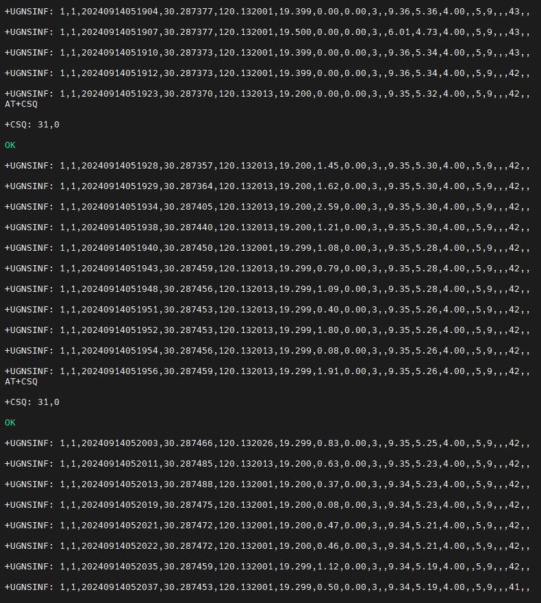
Wait for a moment, and the device will then be able to acquire its location. | |||
http://www.mcuzone.com/wiki/1003_Zero_4G_Cat1-Hub/1003_Zero_4G_Cat1-Hub_27.jpg | http://www.mcuzone.com/wiki/1003_Zero_4G_Cat1-Hub/1003_Zero_4G_Cat1-Hub_27.jpg | ||
2024年10月21日 (一) 15:07的版本
Keywords
Raspberry Pi Zero, Zero 2W, Cat1 4G LTE, USB2.0, USB Type-C, USB HUB, Nano SIM, RPi-Connect, Remote connection
I. Introduction
The Raspberry Pi Zero series (including the Zero, Zero W/H, and Zero 2W) is a highly cost-effective embedded system platform, known for its small size, low power consumption, and acceptable performance, making it suitable for many lightweight application scenarios. Although the Zero series is compact, it reserves a large number of expansion interfaces. Especially on the backside of the board, gold-plated test points for USB and power are brought out. We can use these sets of USB and power test points to expand various types of peripherals.
This expansion board is essentially a USB hub that connects to the Zero's USB port via pogo pins. It expands four USB ports via USB, with one USB port converted to a 4G Cat1 module, and three USB 2.0-A host ports.
4G Cat1 is a high-cost-performance module aimed at medium-speed IoT applications around 10 Mbps. The 10 Mbps downlink and 5 Mbps uplink speeds can satisfy the majority of connectivity and transmission requirements. The CAT1 module is driver-free and automatically recognized in the Raspberry Pi OS, Ubuntu system, and OpenWrt system, making it easy to use.
II. Hardware Spec
1. This expansion board connects to the Raspberry Pi Zero's USB port and power contacts via four pogo pins for both power supply and communication.
2. A USB-C power port is provided, which functions are the same as the power port on the Raspberry Pi Zero itself. You can choose to use either one, but not both simultaneously.
3. The board includes a 4G CAT1 module, with an option for a 4G module that includes GPS functionality. Users in other countries can also select other CAT1 modules that match their frequency bands.
4. Uses a Nano SIM card slot (located on the reverse side). Please refer to the silkscreen on the board for the direction in which the SIM card should be inserted.
5. It uses a first-generation IPEX connector, which can be used with external 4G FPC or rod antennas. If the GPS version is selected, a passive GPS antenna is required, and the antenna must be placed outside the window to achieve positioning.
6. The board features three USB 2.0 Type-C host interfaces, with each USB port capable of supplying 1A of power (Note: the Raspberry Pi Zero's own OTG functionality will no longer be usable, and the Zero's own micro USB port cannot be used to connect any USB devices, otherwise, this expansion board will not function properly).
7. Reserve the debugging serial port and the AT main serial port, both with 3.3V voltage levels.
8. There are three LED indicator lights; one is the power indicator for the expansion board, and another is the power indicator for the 4G module. The NET LED indicates the network status: a 1.8-second on and 0.2-second off cycle indicates successful network registration, while a 1.8-second off and 0.2-second on cycle indicates that the device has not registered with the network, and you should check the SIM card and antenna.
9. The board features positions for the BOOT and reset buttons.
10. Sizes: 66*30mm, with four M2.5 mounting holes, each with a height of 5mm. The board size is fully compatible with the Raspberry Pi Zero series boards.
11. An optional 3D printed base is available to protect the circuit board.
12. The circuit board uses an ENIG (Electroless Nickel Immersion Gold) process, is produced without lead, and the PCB has received UL and RoHS certifications, with a fire protection rating of 94V-0.


III. System flashing
3.1 Overview
The hardware in this document is based on the Raspberry Pi Zero 2W.
1. The Raspberry Pi OS used in this document is: 2024-07-04-raspios-bookworm-arm64.img.xz(Raspberry Pi OS with desktop).
(If you are using the Raspberry Pi Zero (1st generation) series boards, they only support 32-bit systems. Please be sure to download the correct version.)
You can download the Raspberry Pi OS in:
https://www.raspberrypi.com/software/operating-systems/#raspberry-pi-os-64-bit
2)Ubuntu系统,Ubuntu Server 24.04 LTS,服务器版(树莓派Zero 2W因为性能关系不能用Desktop版),镜像为ubuntu-24.04-preinstalled-server-arm64+raspi.img.xz
Ubuntu系统下载地址:
https://ubuntu.com/download/raspberry-pi
2. Ubuntu system: Ubuntu Server 24.04 LTS. (The Raspberry Pi Zero 2W cannot use the Desktop version due to performance limitations.)
The image is: ubuntu-24.04-preinstalled-server-arm64+raspi.img.xz
You can download the Ubuntu system in:
https://ubuntu.com/download/raspberry-pi
(If using the first-generation Raspberry Pi Zero board, which only supports 32-bit systems, there may not be a suitable Ubuntu Server system available.)
3.2 Flash the OS image in TF card
Click here to read the instructions for System flashing
IV. Work with Raspberry Pi OS
☆ 4.1 View hardware devices
4.1.1 Hardware connection
This expansion board features four USB Type-C ports. One of these USB Type-C ports is labeled as PWR on the silkscreen on the back, indicating it is the power input USB Type-C port. The remaining three USB Type-C ports are HOST ports, which can be used to connect USB devices such as keyboards, mice, and USB drives, among other peripherals. Above the 4G module, there are two antenna connectors; one is for the 4G signal antenna, and the other is for the GPS signal antenna. All peripherals are driver-free, meaning they are plug-and-play.
The Raspberry Pi Zero board is fixed above the expansion board using four screws. Please pay attention to the installation direction and ensure that the pogo pins on the expansion board align with the corresponding contacts on the Zero board. Connect the HDMI cable and power supply, and note that the Zero's micro USB port should not be connected to any devices.
4.1.2 View USB devices
Open the terminal in Raspberry Pi OS and enter the commandlsusb, as shown in the image below:

The system has detected the USB hub and the 4G module:
Device 002: External USB Hub;
Device 003: 4G module;
Device 004: USB2.0 Type-C interface;
If the system stop at the Raspberry Pi logo and fails to boot:
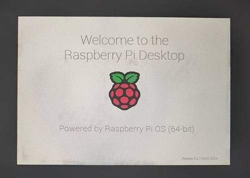
or if after booting, the keyboard, mouse, and 4G module cannot be used,
please carefully check whether the pogo pins are aligned with the gold-plated contacts. Additionally, on the PC, open the config.txt file located in the root directory of the TF card to check the USB initialization script.
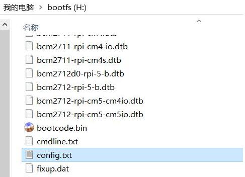
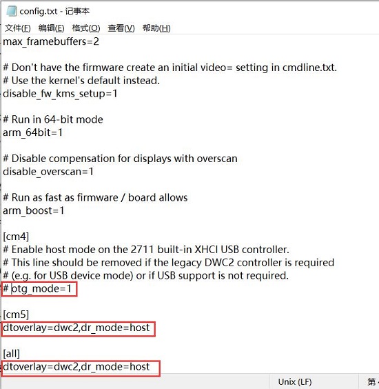
You need to confirm that the three red-boxed areas in the following image are all configured completely. If not, please manually add the missing parts and save the file:
# otg_mode=1 (It is recommended to comment out as follow)
dtoverlay=dwc2,dr_mode=host (These two areas must be ensured to be included.)
4.1.3 View 4G module
Open the terminal in Raspberry Pi OS and enter the commandifconfig -a, as shown in the image below:
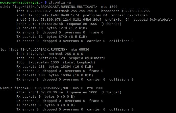
You can see that eth0 as the 4G Cat1 (which has automatically connected, with the default IP address in the above example being 192.168.10.2), and wlan0 as the wireless network card that comes with the Zero 2W.
☆ 4.2 Test 4G module
4.2.1 Operations on 4G when the system has not set up WiFi
When the Raspberry Pi OS boots, WiFi is enabled by default, but it is not connected to any access point (meaning no WiFi account and password are set in the system). So when connecting to the internet via the 4G module, we can perform a ping operation:
Ping the IP should correctly display as follows:

Ping the domain name should correctly display as follows:

This indicates that the 4G connection is normal.
Solution for ping domain error:
If you encounter a ping domain error, as shown in the image:

This indicates that the DNS server settings for the 4G module are incorrect. Let's modify the DNS server settings:
First, we need to connect to WiFi:
Click on the network icon in the upper right corner and select the AP you want to connect to:
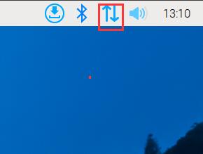
Enter the password (if there is one), and then click "Connect":
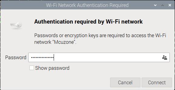
After a successful connection, you can obtain the IP address of the router and access the internet normally:
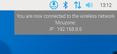
Install the DNS server switching software udhcpc:
sudo apt install udhcpc
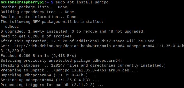
After installation, use the following command to switch the DNS server to the 4G module (in this case, eth0 represents the 4G module; the name may differ depending on the software and hardware platform):
sudo udhcpc -i eth0
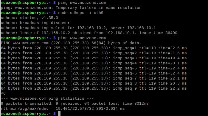
This way, you achieve normal internet browsing via 4G.
The method of switching DNS servers for 4G internet access will stop working after the system is restarted. If you want the DNS server to automatically switch to the 4G module each time the system starts, you can follow these steps:
Open rc-local service:
sudo systemctl enable --now rc-local
Use the following command to open rc.local:
sudo nano /etc/rc.local
Add the command you want to execute at startup above the line exit 0, and then save the file (in this example, eth0 represents the 4G module, but the name should match the actual interface identified on your system):
sleep 5 && sudo udhcpc -i eth0 && sleep 5 && sudo udhcpc -i eth0 && sleep 5 && sudo udhcpc -i eth0
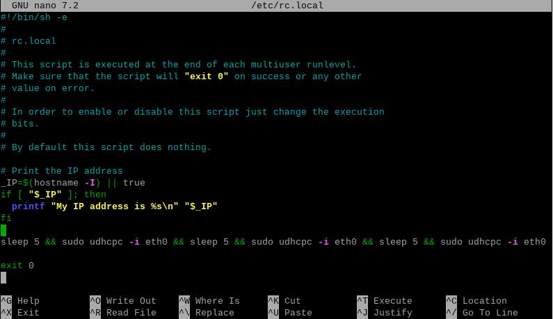
The sleep command is used to delay the execution of subsequent commands by a certain number of seconds. Since the 4G module needs some time to acquire an IP address, to prevent `udhcpc` from failing, it needs to be executed several times with a delay added between each execution. As a result, the 4G network becomes usable approximately 20 seconds after the system boots up.
4.2.2 The system has already been set up for WiFi connectivity, and the operations for the 4G connection
If your system was previously set up with WiFi, the Raspberry Pi Zero 2W will provide internet access via WiFi when used alone. When you install our expansion board, upon rebooting the system, it will prioritize using the 4G network for internet access. If you want to switch to WiFi, you can follow these steps:
Disable the 4G network connection:
sudo ifconfig eth0 down

Use udhcpc to switch the DNS server to the WiFi's DNS server.
sudo udhcpc -i wlan0

If you later want to switch back to browsing the internet using the 4G network, you can run:
sudo ifconfig eth0 up
sudo ifconfig wlan0 down
sudo udhcpc -i eth0
4.2.3 Access the 4G module via SSH over WiFi
If you want to enable SSH using the Raspberry Pi ZERO's WiFi to subsequently perform 4G operations on the Raspberry Pi, you need to set up the SSH service before flashing the system. For the steps, refer to this guide.
☆ 4.3 How to use AT commands and GPS
4.3.1 Open AT serial
Execute the command in the SSH terminal:
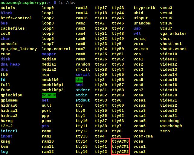
ls /dev
You should be able to see three devices named ttyACM0, ttyACM1, and ttyACM2 under the dev directory:
Install minicom:
sudo apt-get install minicom

Open AT Command serial port by minicom:
sudo minicom -D /dev/ttyACM0
Note: When using a serial port, ensure that after entering this port, you can input and run AT commands without any garbled output or unexpected jumps in the results.
4.3.2 Execute AT commands
The following uses minicom as an example:
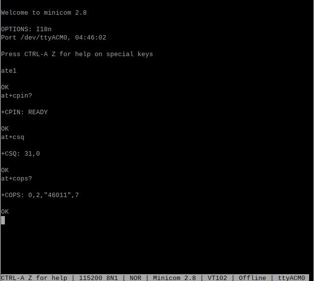
Then directly type the AT command and press Enter to see the result. If you need to view the echo, please type the command: ate1:
Use AT+CPIN? to check if the SIM card is properly inserted and recognized;
Use AT+CSQ to check the signal strength; the first value ranges from 0-31, and a value of 25 or above is considered good signal quality;
Use AT+COPS? to check the network registration status; the quotation marks contain the operator code, and the last digit represents the network mode, with 7 indicating 4G.
4.3.3 GPS Test (only for GPS version)
When using GPS, you need to connect a passive GPS antenna and ensure that the GPS antenna is extended outdoors.
Run minicom and open the ttyACM0 serial port:
sudo minicom -D /dev/ttyACM0
And execute:
AT+CGNSPWR=1 //Open GPS
AT+CGNSAID=31,1,1,1 //Enable location assistance positioning (the command will immediately return OK, and positioning will succeed in about 2-10 seconds based on signal strength).
AT+CGNSURC=1 //Setup automatic reporting of location information
After running successfully, you will be able to see GPS information output from the serial port: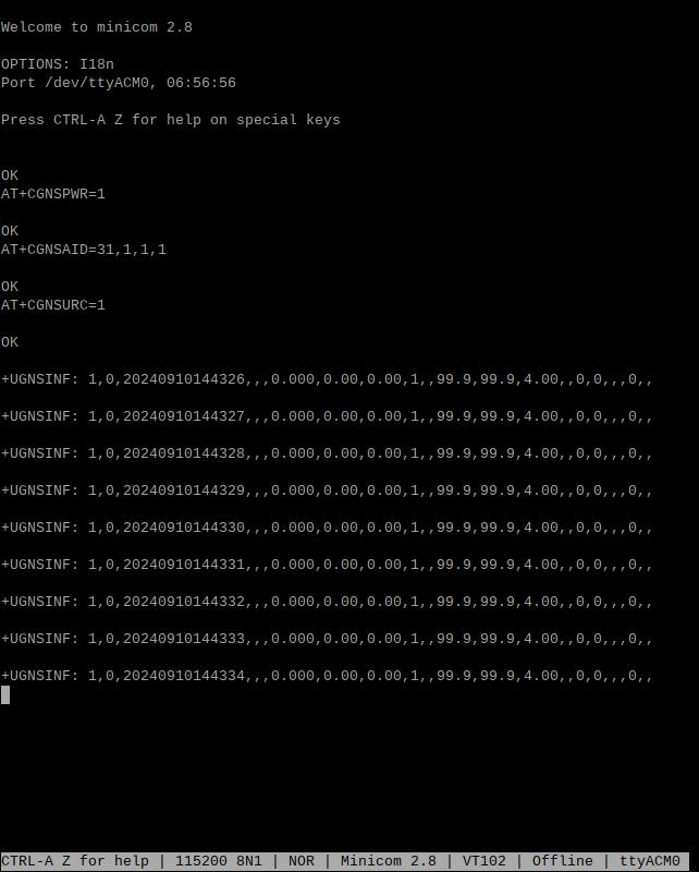
Wait for a moment, and the device will then be able to acquire its location.
五、Ubuntu系统的使用
5.1 编辑初始化脚本
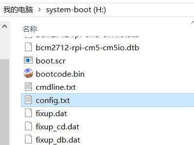
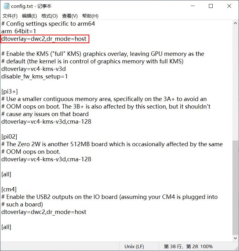
Ubuntu Server烧写完毕后,请在PC端打开TF卡系统分区根目录下的config.txt检查USB的初始化脚本,Ubuntu Server对USB初始化了两遍,前面一遍没有配置成host模式,需要确认下图中的红框的位置是否配置成完全,如果没有,请手动添加完整:
dtoverlay=dwc2,dr_mode=host
5.2 配置用户名和密码
将TF卡插入Zero 2W,启动系统。第一次启动后会要求登录,用户名和密码均为ubuntu,登录成功后会要求修改密码。

修改完毕后就自动进入系统。
5.3 配置网络
系统启动后并无网络可用,需要进行后续设置后才能使用。
注意,系统默认并没有集成ifconfig工具,只有ip命令可用。
执行ip addr查看并记录下网卡名称:

其中2号网卡(enx2089846a96ab)为4G模组。
然后运行下面的命令,打开网卡配置文件:
sudo nano /etc/netplan/50-cloud-init.yaml
按照下图编辑网卡配置文件:
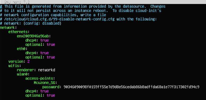
保存退出,然后重启。
重启后即可联网,安装net-tools工具以便于使用:
sudo apt install net-tools
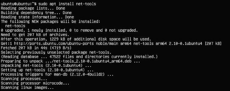
执行ifconfig -a,可以看见4G模块已经正确获得了IP地址:
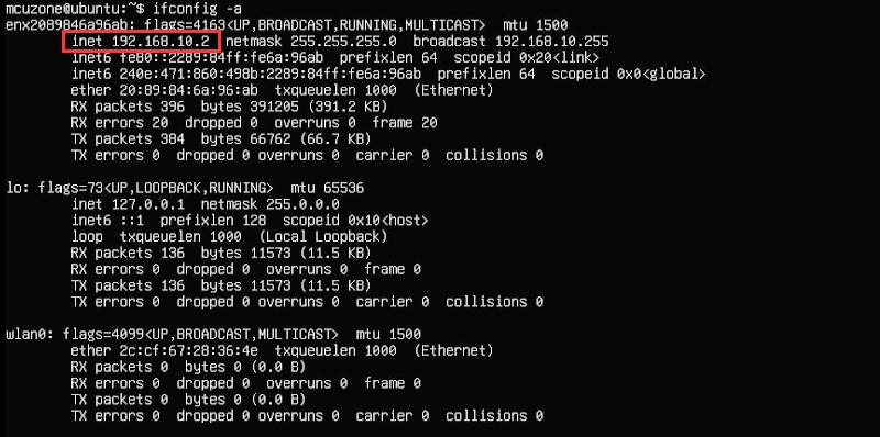
5.4 测试AT命令
执行命令:
ls /dev
此时应该能看到dev设备下有ttyACM0-2三个设备:
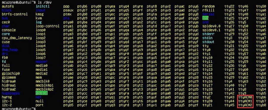
下载安装minicom工具:
sudo apt-get install minicom

通过minicom打开AT命令串口:
sudo minicom -D /dev/ttyACM0
注意,使用哪个串口,应以在进入此串口后,可输入运行AT命令,显示不乱码,不乱跳结果为准。
下面以minicom为例,如果需要查看回显,请键入命令:ate1,然后回车,继续键入其它命令,回车可以看到结果。
用AT+CPIN?来检查SIM是否正常插入并识别;
用AT+CSQ来检查信号强度,第一个值是0-31,需要25以上才算信号质量良好;
用AT+COPS?来检查注网情况,双引号内是运营商代码,最后一个数字是网络模式,7代表4G。
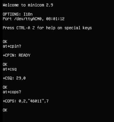
常用AT命令:
1. 检查SIM卡是否识别到:
at+cpin?
返回ready表示卡已识别,返回error要检查硬件
2. 检查天线信号质量:
at+csq
返回值在26-31表示信号OK,信号满格31;返回值在20-25表示信号勉勉强强;返回值在20以下表示信号比较糟糕或者天线没接
3. 检查注网情况:
at+cops?
正常应该返回运营商代码和7,7代表4G。
注意,以上命令只有at+csq不要加问号,另外两条命令需要加问号。
4. 查看4G模块的IMEI码:
at+cgsn
5. 重启4G模块(有时候如果重插SIM卡,热插拔不一定管用,可以用这个reset命令来复位模块):
at+reset
6. 关闭射频:
at+cfun=0
开启射频:
at+cfun=1
上述两条命令成对使用,可以在不重启4G模组的情况下让模组重新注网。
六、(应用)Raspberry Pi Connect远程连接树莓派
RPi-Connect提供了从任何地方安全接入到树莓派的服务。基于此服务,搭配Zero_Cat1_4G Cat1-Hu版即可实现在户外没有无线网络的情况下,依旧可以远程访问树莓派操作。注意:要使用此服务必须运行Bookworm及以上系统。同时,只有树莓派5,4或400可以使用屏幕分享。Zero2W只能使用Remote shell。接下来演示如何配置远程连接服务。
6.1 申请Raspberry Pi ID
如果已有Raspberry Pi ID请直接登录,如果没有请按下列步骤申请。
打开在https://id.raspberrypi.com/,输入您要使用的邮箱以及密码:

创建账号完成后需要进入邮箱验证:
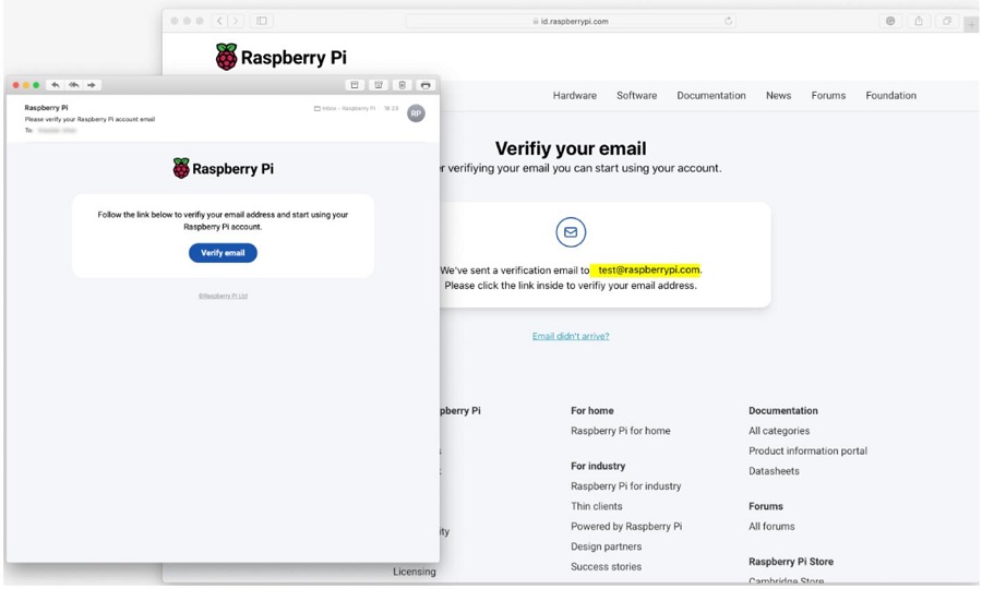
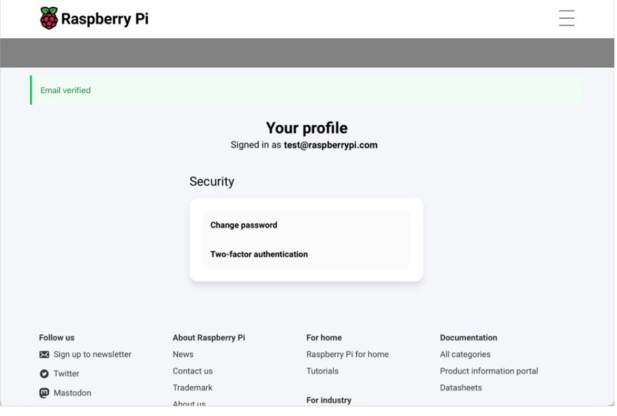
验证完成后即可使用该id。
6.2 安装远程服务
打开树莓派终端,安装Raspberry Pi Connect软件,如果安装时显示已安装则不需另外安装:
sudo apt install rpi-connect
安装完成后,我们在终端输入loginctl enable-linger确保每次重启后系统自动打开远程服务。

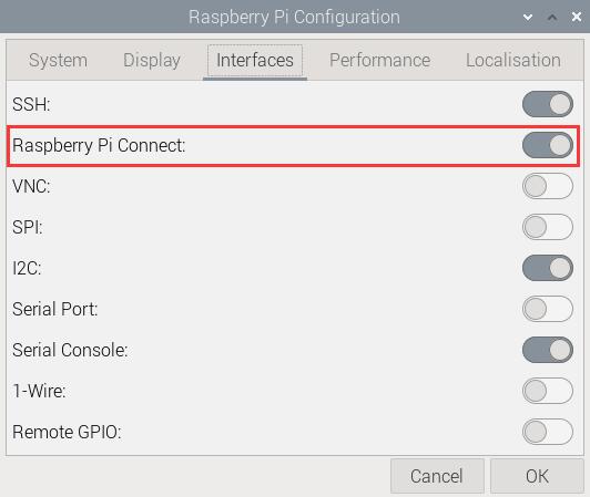
重启系统,在图形界面中,依次选择如下图项目后,确保Raspberry Pi Connect已打开:
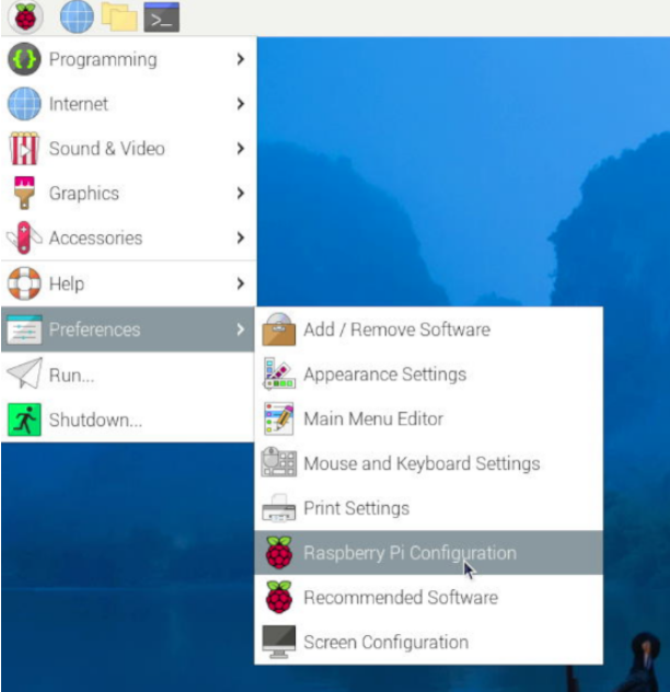
然后在树莓派终端输入:
rpi-connect signin

此时显示一个网址,如上图所示,我们在浏览器(建议使用别的电脑,Zero系列因为硬件资源关系,打开浏览器时非常缓慢)中打开这个网址:
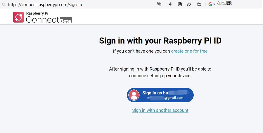
点击Sign in,按照提示进行绑定即可,首先需要设置设备名称:
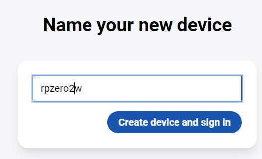
点击Create device and sign in:
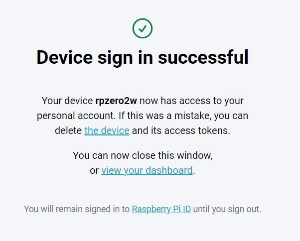
这样就完成了绑定,终端中也会有成功的显示:

6.3 使用远程控制
在PC上打开:https://connect.raspberrypi.com/devices:

刚才添加的Zero 2W设备下面只有”Remote shell“字样,表示此设备只能通过远程命令行界面控制。
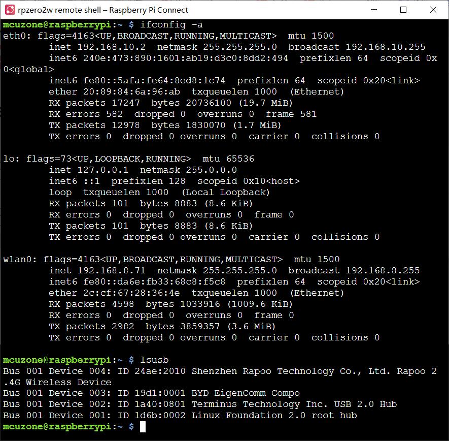
点击Connect,弹出远程命令行界面,即可输入命令:
联系我们
电话:13957118045
如本页面有任何疏漏、错误或者侵权,请通过上述途径联系我们,谢谢!
Copyright 2004-2024 野芯科技


 QQ:8204136