0025 MPDTPU(M.2 E) EN:修订间差异
(创建页面,内容为“== '''关键词''' == 树莓派5、PCIe、TPU、DTPU、Edge TPU、驱动安装、操作演示、AI、google、Coral、PCIe Switch、M.2 E key == '''一、简介''' == MPDTPU是一款专为树莓派5设计的双TPU扩展板,通过16Pin FPC接口连接至树莓派5,扩展板上通过一颗一扩二的PCIe Switch芯片来驱动双TPU模组。Coral的双TPU模组板载了两颗Google的Edge TPU处理器,使用了非标的M.2 E key接口。双TPU模组可提…”) |
无编辑摘要 |
||
| 第1行: | 第1行: | ||
[[0025 MPDTPU(M.2 E)|切换语言为中文]] | |||
== ''' | == '''Keywords''' == | ||
Raspberry Pi5, PCIe, TPU, DTPU, Edge TPU, Driver installation, Operation demonstration, AI, google, Coral, PCIe Switch, M.2 E key | |||
== ''' | == '''I. Introduction''' == | ||
The MPDTPU is a dedicated dual-TPU expansion board designed for the Raspberry Pi 5. It connects to the Raspberry Pi 5 via a 16-pin FPC interface. On the expansion board, a PCIe Switch chip that expands one port into two is used to drive the dual-TPU modules. The Coral dual-TPU module is equipped with two Google Edge TPU processors and uses a non-standard M.2 E key interface. The dual-TPU module provides a total performance of 8 TOPS, with an efficiency of 2 TOPS/W. | |||
== '''II. Hardware Resources''' == | |||
1. Using a 16-pin PCIe interface, the board is equipped with a one-to-two PCIe Switch chip. | |||
2. On-board M.2 E-key connector 2230, supporting dual-TPU modules. | |||
3. The TPU module is powered through a 16-pin PCIe interface and can also be powered through a 40-pin interface. | |||
4. Equipped with an INA219 voltage and current sampling circuit, it can monitor the power consumption of dual-TPU operations. | |||
5. Equipped with a 40-pin SMT receptacle, it can be connected to the 40-pin header of the Raspberry Pi 5 using a PC104 connector. | |||
6. An optional 24C32 E2PROM can be used to store device initialization information. | |||
7. Size: 56x65mm, the PCB board is certified by UL and ROHS, and has a fire rating of 94V-0. | |||
9. | 8. Designed with four layers for efficient heat conduction, it includes standard thermal silicone pads and optional heat sinks. | ||
9. Optional aluminum alloy enclosure. | |||
http://www.mcuzone.com/wiki/0025_MPDTPU/0025_MPDTPU_32.jpg | http://www.mcuzone.com/wiki/0025_MPDTPU/0025_MPDTPU_32.jpg | ||
== ''' | == '''III. System flashing''' == | ||
3.1 | 3.1 The Raspberry Pi OS used in this document is: 2024-07-04-raspios-bookworm-armhf.img.xz(Raspberry Pi OS with desktop)。 | ||
You can download it in: | |||
https://www.raspberrypi.com/software/operating-systems/#raspberry-pi-os-64-bit | <nowiki>https://www.raspberrypi.com/software/operating-systems/#raspberry-pi-os-64-bit</nowiki> | ||
3.2 | 3.2 Use Imager or balenaEtcher to flash the OS image in TF card. [[0005 MPS2242 2280 2280P(Single SSD Expansion Board)#3.2 Boot from TF card|Click here to read the instructions for System flashing]] | ||
''''' | '''''Note: The TF card used for flashing the system should have a space of at least 16GB, otherwise, it will display space errors during the installation and configuration process!''''' | ||
== ''' | == '''IV. Driver installation, configuration and demonstration in Raspberry Pi OS''' == | ||
''''' | '''''Note: The operation requires a stable internet connection to the regions out of China (you may need to find your own method). Otherwise, many files may not download or may only partially download, which could ultimately lead to the code failing to run.''''' | ||
=== 4.1 | === 4.1 Config config.txt === | ||
After the system starts, open the Raspberry Pi terminal and enter the command: | |||
<code>sudo nano /boot/firmware/config.txt</code> | <code>sudo nano /boot/firmware/config.txt</code> | ||
Or: | |||
<code>sudo mousepad /boot/firmware/config.txt</code> | <code>sudo mousepad /boot/firmware/config.txt</code> | ||
Add the codes in the ending of this file: | |||
<code>dtparam=pciex1</code> | <code>dtparam=pciex1</code> | ||
| 第61行: | 第63行: | ||
http://www.mcuzone.com/wiki/0006_MPW7_TPU/0006_MPW7_TPU_02.jpg | http://www.mcuzone.com/wiki/0006_MPW7_TPU/0006_MPW7_TPU_02.jpg | ||
Then, save the file and reboot the system: | |||
<code>sudo reboot</code> | <code>sudo reboot</code> | ||
=== 4.2 | === 4.2 Ensuring software environment === | ||
After reboot the system, open the Raspberry Pi terminal and enter the command: | |||
<code>uname -r</code> | <code>uname -r</code> | ||
After ensuring the kernel version is greater than 4.18, enter: | |||
<code>lsmod | grep apex</code> | <code>lsmod | grep apex</code> | ||
Ensure there is no output, then you can begin installing the TPU driver. | |||
http://www.mcuzone.com/wiki/0006_MPW7_TPU/0006_MPW7_TPU_03.jpg | http://www.mcuzone.com/wiki/0006_MPW7_TPU/0006_MPW7_TPU_03.jpg | ||
=== 4.3 | === 4.3 Install necessary software === | ||
Ensure the network is connected to internet connection to the regions out of China (you may need to find your own method), and then add the Google TPU software library: | |||
<code>echo "deb <nowiki>https://packages.cloud.google.com/apt</nowiki> coral-edgetpu-stable main" | sudo tee /etc/apt/sources.list.d/coral-edgetpu.list</code> | <code>echo "deb <nowiki>https://packages.cloud.google.com/apt</nowiki> coral-edgetpu-stable main" | sudo tee /etc/apt/sources.list.d/coral-edgetpu.list</code> | ||
| 第87行: | 第89行: | ||
http://www.mcuzone.com/wiki/0006_MPW7_TPU/0006_MPW7_TPU_04.jpg | http://www.mcuzone.com/wiki/0006_MPW7_TPU/0006_MPW7_TPU_04.jpg | ||
Update the software list after adding: | |||
<code>sudo apt-get update</code> | <code>sudo apt-get update</code> | ||
| 第93行: | 第95行: | ||
http://www.mcuzone.com/wiki/0006_MPW7_TPU/0006_MPW7_TPU_06.jpg | http://www.mcuzone.com/wiki/0006_MPW7_TPU/0006_MPW7_TPU_06.jpg | ||
Install the necessary software after the update is completed: | |||
<code>sudo apt-get install cmake libedgetpu1-std devscripts debhelper dkms dh-dkms</code> | <code>sudo apt-get install cmake libedgetpu1-std devscripts debhelper dkms dh-dkms</code> | ||
| 第101行: | 第103行: | ||
http://www.mcuzone.com/wiki/0006_MPW7_TPU/0006_MPW7_TPU_08.jpg | http://www.mcuzone.com/wiki/0006_MPW7_TPU/0006_MPW7_TPU_08.jpg | ||
=== 4.4 | === 4.4 Install Gasket Driver === | ||
Enter the following commands in sequence to install the Gasket Driver: | |||
<code>git clone <nowiki>https://github.com/google/gasket-driver.git</nowiki></code> | <code>git clone <nowiki>https://github.com/google/gasket-driver.git</nowiki></code> | ||
| 第120行: | 第122行: | ||
http://www.mcuzone.com/wiki/0006_MPW7_TPU/0006_MPW7_TPU_11.jpg | http://www.mcuzone.com/wiki/0006_MPW7_TPU/0006_MPW7_TPU_11.jpg | ||
After the installation is complete, enter the following command to ensure that the driver and software were installed successfully: | |||
<code>sudo apt-get install gasket-dkms libedgetpu1-std</code> | <code>sudo apt-get install gasket-dkms libedgetpu1-std</code> | ||
| 第126行: | 第128行: | ||
http://www.mcuzone.com/wiki/0006_MPW7_TPU/0006_MPW7_TPU_12.jpg | http://www.mcuzone.com/wiki/0006_MPW7_TPU/0006_MPW7_TPU_12.jpg | ||
Then, add a udev rule to obtain device operation permissions: | |||
<code>sudo sh -c "echo 'SUBSYSTEM==\"apex\", MODE=\"0660\", GROUP=\"apex\"' >> /etc/udev/rules.d/65-apex.rules"</code> | <code>sudo sh -c "echo 'SUBSYSTEM==\"apex\", MODE=\"0660\", GROUP=\"apex\"' >> /etc/udev/rules.d/65-apex.rules"</code> | ||
add user to apex: | |||
<code>sudo groupadd apex</code> | <code>sudo groupadd apex</code> | ||
| 第138行: | 第140行: | ||
http://www.mcuzone.com/wiki/0006_MPW7_TPU/0006_MPW7_TPU_13.jpg | http://www.mcuzone.com/wiki/0006_MPW7_TPU/0006_MPW7_TPU_13.jpg | ||
Reboot the system after the setup is complete: | |||
<code>sudo reboot</code> | <code>sudo reboot</code> | ||
=== 4.5 | === 4.5 Verification module testing and driver installation === | ||
After system starting, verification module testing and driver installation: | |||
<code>lspci -nn | grep 089a</code> | <code>lspci -nn | grep 089a</code> | ||
| 第151行: | 第153行: | ||
http://www.mcuzone.com/wiki/0025_MPDTPU/0025_MPDTPU_01.jpg | http://www.mcuzone.com/wiki/0025_MPDTPU/0025_MPDTPU_01.jpg | ||
This board has a dual-TPU onboard, so you can see two TPU modules: | |||
By entering <code>sudo lspci -v</code>, you can see the driver loading. There are also drivers for the two TPU modules. | |||
http://www.mcuzone.com/wiki/0025_MPDTPU/0025_MPDTPU_02.jpg | http://www.mcuzone.com/wiki/0025_MPDTPU/0025_MPDTPU_02.jpg | ||
=== 4.6 | === 4.6 Configuration of the Code Execution Environment === | ||
Google | Running Google TPU module code requires Python versions between 3.6 and 3.9, while the latest Raspberry Pi system is Python 3.11. Therefore, we need to use Pyenv to download an older version of Python. | ||
First, install the depends: | |||
<code>sudo apt-get install -y make build-essential libssl-dev zlib1g-dev \libbz2-dev libreadline-dev libsqlite3-dev wget curl llvm libncurses5-dev \libncursesw5-dev xz-utils tk-dev libffi-dev liblzma-dev python3-openssl</code> | <code>sudo apt-get install -y make build-essential libssl-dev zlib1g-dev \libbz2-dev libreadline-dev libsqlite3-dev wget curl llvm libncurses5-dev \libncursesw5-dev xz-utils tk-dev libffi-dev liblzma-dev python3-openssl</code> | ||
| 第168行: | 第170行: | ||
http://www.mcuzone.com/wiki/0006_MPW7_TPU/0006_MPW7_TPU_18.jpg | http://www.mcuzone.com/wiki/0006_MPW7_TPU/0006_MPW7_TPU_18.jpg | ||
Install pyenv after the depends are installed: | |||
<code>curl <nowiki>https://pyenv.run</nowiki> | bash</code> | <code>curl <nowiki>https://pyenv.run</nowiki> | bash</code> | ||
| 第174行: | 第176行: | ||
http://www.mcuzone.com/wiki/0006_MPW7_TPU/0006_MPW7_TPU_19.jpg | http://www.mcuzone.com/wiki/0006_MPW7_TPU/0006_MPW7_TPU_19.jpg | ||
Enter the command: | |||
<code>sudo nano ~/.bashrc</code> | <code>sudo nano ~/.bashrc</code> | ||
Or: | |||
<code>sudo mousepad ~/.bashrc</code> | <code>sudo mousepad ~/.bashrc</code> | ||
Add the codes in the ending of this file: | |||
<code>export PYENV_ROOT="$HOME/.pyenv"</code> | <code>export PYENV_ROOT="$HOME/.pyenv"</code> | ||
| 第194行: | 第196行: | ||
http://www.mcuzone.com/wiki/0006_MPW7_TPU/0006_MPW7_TPU_21.jpg | http://www.mcuzone.com/wiki/0006_MPW7_TPU/0006_MPW7_TPU_21.jpg | ||
Save and exit after adding, then reload the shell: | |||
<code>exec "$SHELL"</code> | <code>exec "$SHELL"</code> | ||
| 第200行: | 第202行: | ||
http://www.mcuzone.com/wiki/0006_MPW7_TPU/0006_MPW7_TPU_22.jpg | http://www.mcuzone.com/wiki/0006_MPW7_TPU/0006_MPW7_TPU_22.jpg | ||
Then, we can use pyenv to install an older version of Python: | |||
<code>pyenv install -v 3.8.8</code> | <code>pyenv install -v 3.8.8</code> | ||
| 第208行: | 第210行: | ||
http://www.mcuzone.com/wiki/0006_MPW7_TPU/0006_MPW7_TPU_24.jpg | http://www.mcuzone.com/wiki/0006_MPW7_TPU/0006_MPW7_TPU_24.jpg | ||
After the installation is successful, we will change the system Python version to 3.8.8: | |||
<code>pyenv global 3.8.8</code> | <code>pyenv global 3.8.8</code> | ||
After the change is successful, you can check the current Python version is 3.8.8: | |||
<code>pyenv versions</code> | <code>pyenv versions</code> | ||
python3 -V | |||
http://www.mcuzone.com/wiki/0006_MPW7_TPU/0006_MPW7_TPU_25.jpg | http://www.mcuzone.com/wiki/0006_MPW7_TPU/0006_MPW7_TPU_25.jpg | ||
=== 4.7 | === 4.7 Download the code and run the module === | ||
Enter the following commands in sequence to download: | |||
<code>mkdir coral && cd coral</code> | <code>mkdir coral && cd coral</code> | ||
| 第237行: | 第239行: | ||
http://www.mcuzone.com/wiki/0006_MPW7_TPU/0006_MPW7_TPU_27.jpg | http://www.mcuzone.com/wiki/0006_MPW7_TPU/0006_MPW7_TPU_27.jpg | ||
Then, download the code and run the module: | |||
<code>pip3 install numpy</code> | <code>pip3 install numpy</code> | ||
| 第251行: | 第253行: | ||
http://www.mcuzone.com/wiki/0006_MPW7_TPU/0006_MPW7_TPU_30.jpg | http://www.mcuzone.com/wiki/0006_MPW7_TPU/0006_MPW7_TPU_30.jpg | ||
=== 4.8 | === 4.8 Run the code === | ||
==== 4.8.1 | ==== 4.8.1 Single-TPU running a single model ==== | ||
Enter the following code to run it: | |||
http://www.mcuzone.com/wiki/0006_MPW7_TPU/0006_MPW7_TPU_39.jpg | http://www.mcuzone.com/wiki/0006_MPW7_TPU/0006_MPW7_TPU_39.jpg | ||
Note: You can copy the following code, but please paste it into a text editor first. Then, following the format shown above, remove any extra enter. After that, copy it again and paste it into the terminal to run. | |||
<code>python3 examples/classify_image.py \</code> | <code>python3 examples/classify_image.py \</code> | ||
| 第273行: | 第272行: | ||
http://www.mcuzone.com/wiki/0025_MPDTPU/0025_MPDTPU_03.jpg | http://www.mcuzone.com/wiki/0025_MPDTPU/0025_MPDTPU_03.jpg | ||
==== 4.8.2 | ==== 4.8.2 Dul-TPU running multiple model ==== | ||
Enter the following code to run it: | |||
http://www.mcuzone.com/wiki/0025_MPDTPU/0025_MPDTPU_06.jpg | http://www.mcuzone.com/wiki/0025_MPDTPU/0025_MPDTPU_06.jpg | ||
Note: You can copy the following code, but please paste it into a text editor first. Then, following the format shown above, remove any extra enter. After that, copy it again and paste it into the terminal to run. | |||
<code>python3 examples/two_models_inference.py \</code> | <code>python3 examples/two_models_inference.py \</code> | ||
| 第292行: | 第291行: | ||
http://www.mcuzone.com/wiki/0025_MPDTPU/0025_MPDTPU_04.jpg | http://www.mcuzone.com/wiki/0025_MPDTPU/0025_MPDTPU_04.jpg | ||
==== 4.8.3 | ==== 4.8.3 Dul-TPU running a single model ==== | ||
Enter the following code to run it: | |||
http://www.mcuzone.com/wiki/0025_MPDTPU/0025_MPDTPU_07.jpg | http://www.mcuzone.com/wiki/0025_MPDTPU/0025_MPDTPU_07.jpg | ||
Note: You can copy the following code, but please paste it into a text editor first. Then, following the format shown above, remove any extra enter. After that, copy it again and paste it into the terminal to run. | |||
<code>python3 examples/model_pipelining_classify_image.py \</code> | <code>python3 examples/model_pipelining_classify_image.py \</code> | ||
| 第311行: | 第310行: | ||
http://www.mcuzone.com/wiki/0025_MPDTPU/0025_MPDTPU_05.jpg | http://www.mcuzone.com/wiki/0025_MPDTPU/0025_MPDTPU_05.jpg | ||
'''<big> | '''<big>You should downloading a large amount of data from the internet out of China to use the testing of this development board, so users can contact our company after buying this development board to obtain a pre-configured Raspberry Pi OS image.</big>''' | ||
== ''' | == '''V. E2PROM chip flashing operation demonstration''' == | ||
=== 5.1 | === 5.1 Overview === | ||
The MPDTPU expansion board is equipped with an E2PROM chip. During the boot process, the Raspberry Pi system will search for the E2PROM via the I2C pins and read the E2PROM information. Therefore, we can write the information and device tree files we need into the E2PROM chip to achieve the functionality of automatic configuration loading. | |||
''''' | '''''Note: The operation requires a stable internet connection to the regions out of China (you may need to find your own method). Otherwise, many files may not download or may only partially download, which could ultimately lead to the code failing to run.''''' | ||
=== 5.2 | === 5.2 Enable I2C === | ||
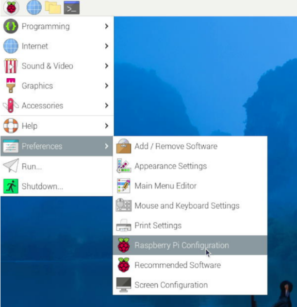
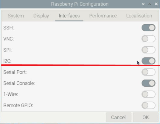
Select the items in the order shown in the following diagram, enable I2C, and then restart the Raspberry Pi OS. | |||
http://www.mcuzone.com/wiki/0002_MPS2280iPoE/MPS2280iPoE_08.png | http://www.mcuzone.com/wiki/0002_MPS2280iPoE/MPS2280iPoE_08.png | ||
| 第327行: | 第326行: | ||
http://www.mcuzone.com/wiki/0002_MPS2280iPoE/MPS2280iPoE_09.png | http://www.mcuzone.com/wiki/0002_MPS2280iPoE/MPS2280iPoE_09.png | ||
=== 5.3 | === 5.3 Install tools === | ||
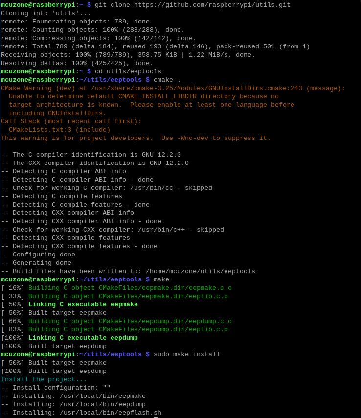
Execute the following commands to install tools: | |||
<code>git clone <nowiki>https://github.com/raspberrypi/utils.git</nowiki></code> | <code>git clone <nowiki>https://github.com/raspberrypi/utils.git</nowiki></code> | ||
| 第342行: | 第341行: | ||
http://www.mcuzone.com/wiki/0025_MPDTPU/0025_MPDTPU_08.jpg | http://www.mcuzone.com/wiki/0025_MPDTPU/0025_MPDTPU_08.jpg | ||
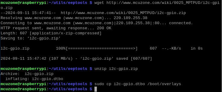
Download and put the i2c-gpio.dtbo file: | |||
<code>wget <nowiki>http://www.mcuzone.com/wiki/0025_MPDTPU/i2c-gpio.zip</nowiki></code> | <code>wget <nowiki>http://www.mcuzone.com/wiki/0025_MPDTPU/i2c-gpio.zip</nowiki></code> | ||
| 第352行: | 第351行: | ||
http://www.mcuzone.com/wiki/0025_MPDTPU/0025_MPDTPU_33.jpg | http://www.mcuzone.com/wiki/0025_MPDTPU/0025_MPDTPU_33.jpg | ||
Reboot the system after completion: | |||
<code>sudo reboot</code> | <code>sudo reboot</code> | ||
=== 5.4 | === 5.4 Edit the configuration file === | ||
Execute the following commands: | |||
<code>cd utils/eeptools</code> | <code>cd utils/eeptools</code> | ||
| 第367行: | 第366行: | ||
http://www.mcuzone.com/wiki/0025_MPDTPU/0025_MPDTPU_11.jpg | http://www.mcuzone.com/wiki/0025_MPDTPU/0025_MPDTPU_11.jpg | ||
Copy all the content of the eeprom_settings.txt and then exit. | |||
Then execute: | |||
<code>sudo mousepad myhat_eeprom.txt</code> | <code>sudo mousepad myhat_eeprom.txt</code> | ||
| 第375行: | 第374行: | ||
http://www.mcuzone.com/wiki/0025_MPDTPU/0025_MPDTPU_12.jpg | http://www.mcuzone.com/wiki/0025_MPDTPU/0025_MPDTPU_12.jpg | ||
Create a file named myhat_eeprom.txt, paste the text you just copied into it, and you can customize the content of the red section. In this demonstration, we will modify the device tree file to disable Bluetooth, which means changing the device tree to <code>disable-bt-pi5</code>. After making these changes, save the file and exit: | |||
http://www.mcuzone.com/wiki/0025_MPDTPU/0025_MPDTPU_27.jpg | http://www.mcuzone.com/wiki/0025_MPDTPU/0025_MPDTPU_27.jpg | ||
Then use the eepmake tool to generate the UUID: | |||
<code>eepmake myhat_eeprom.txt myhat.eep</code> | <code>eepmake myhat_eeprom.txt myhat.eep</code> | ||
| 第385行: | 第384行: | ||
http://www.mcuzone.com/wiki/0025_MPDTPU/0025_MPDTPU_28.jpg | http://www.mcuzone.com/wiki/0025_MPDTPU/0025_MPDTPU_28.jpg | ||
Modify the generated UUID in myhat_eeprom.txt, then save and exit: | |||
http://www.mcuzone.com/wiki/0025_MPDTPU/0025_MPDTPU_29.jpg | http://www.mcuzone.com/wiki/0025_MPDTPU/0025_MPDTPU_29.jpg | ||
Execute the following commands to enable I2C-9 and view the result: | |||
<code>sudo dtoverlay i2c-gpio i2c_gpio_sda=0 i2c_gpio_scl=1 bus=9</code> | <code>sudo dtoverlay i2c-gpio i2c_gpio_sda=0 i2c_gpio_scl=1 bus=9</code> | ||
| 第397行: | 第396行: | ||
http://www.mcuzone.com/wiki/0025_MPDTPU/0025_MPDTPU_16.jpg | http://www.mcuzone.com/wiki/0025_MPDTPU/0025_MPDTPU_16.jpg | ||
Please modify the address within the eepflash.sh script so that it points to 0050: | |||
<code>sudo nano eepflash.sh</code> | <code>sudo nano eepflash.sh</code> | ||
| 第405行: | 第404行: | ||
http://www.mcuzone.com/wiki/0025_MPDTPU/0025_MPDTPU_18.jpg | http://www.mcuzone.com/wiki/0025_MPDTPU/0025_MPDTPU_18.jpg | ||
Then save and exit. | |||
=== 5.5 | === 5.5 Programming the EEPROM === | ||
Execute the following command to program the EEPROM: | |||
sudo ./eepflash.sh -w -t=24c32 -a=0x50 -f=myhat.eep | sudo ./eepflash.sh -w -t=24c32 -a=0x50 -f=myhat.eep | ||
| 第414行: | 第413行: | ||
http://www.mcuzone.com/wiki/0025_MPDTPU/0025_MPDTPU_19.jpg | http://www.mcuzone.com/wiki/0025_MPDTPU/0025_MPDTPU_19.jpg | ||
After programming is complete, reboot the system, and you will see that Bluetooth is disabled. | |||
http://www.mcuzone.com/wiki/0025_MPDTPU/0025_MPDTPU_20.jpg | http://www.mcuzone.com/wiki/0025_MPDTPU/0025_MPDTPU_20.jpg | ||
== ''' | == '''VI. Voltage and current monitoring function demonstration''' == | ||
The MPDTPU expansion board adds voltage and current detection functionality. Using this expansion board, you can monitor real-time voltage, current, and power data of the dual-TPU. | |||
1. | 1. Follow Section 5.2 to enable I2C in the Raspberry Pi OS. | ||
2. 执行下列命令,安装python库: | 2. 执行下列命令,安装python库: | ||
2024年10月17日 (四) 16:34的版本
Keywords
Raspberry Pi5, PCIe, TPU, DTPU, Edge TPU, Driver installation, Operation demonstration, AI, google, Coral, PCIe Switch, M.2 E key
I. Introduction
The MPDTPU is a dedicated dual-TPU expansion board designed for the Raspberry Pi 5. It connects to the Raspberry Pi 5 via a 16-pin FPC interface. On the expansion board, a PCIe Switch chip that expands one port into two is used to drive the dual-TPU modules. The Coral dual-TPU module is equipped with two Google Edge TPU processors and uses a non-standard M.2 E key interface. The dual-TPU module provides a total performance of 8 TOPS, with an efficiency of 2 TOPS/W.
II. Hardware Resources
1. Using a 16-pin PCIe interface, the board is equipped with a one-to-two PCIe Switch chip.
2. On-board M.2 E-key connector 2230, supporting dual-TPU modules.
3. The TPU module is powered through a 16-pin PCIe interface and can also be powered through a 40-pin interface.
4. Equipped with an INA219 voltage and current sampling circuit, it can monitor the power consumption of dual-TPU operations.
5. Equipped with a 40-pin SMT receptacle, it can be connected to the 40-pin header of the Raspberry Pi 5 using a PC104 connector.
6. An optional 24C32 E2PROM can be used to store device initialization information.
7. Size: 56x65mm, the PCB board is certified by UL and ROHS, and has a fire rating of 94V-0.
8. Designed with four layers for efficient heat conduction, it includes standard thermal silicone pads and optional heat sinks.
9. Optional aluminum alloy enclosure.

III. System flashing
3.1 The Raspberry Pi OS used in this document is: 2024-07-04-raspios-bookworm-armhf.img.xz(Raspberry Pi OS with desktop)。
You can download it in:
https://www.raspberrypi.com/software/operating-systems/#raspberry-pi-os-64-bit
3.2 Use Imager or balenaEtcher to flash the OS image in TF card. Click here to read the instructions for System flashing
Note: The TF card used for flashing the system should have a space of at least 16GB, otherwise, it will display space errors during the installation and configuration process!
IV. Driver installation, configuration and demonstration in Raspberry Pi OS
Note: The operation requires a stable internet connection to the regions out of China (you may need to find your own method). Otherwise, many files may not download or may only partially download, which could ultimately lead to the code failing to run.
4.1 Config config.txt
After the system starts, open the Raspberry Pi terminal and enter the command:
sudo nano /boot/firmware/config.txt
Or:
sudo mousepad /boot/firmware/config.txt
Add the codes in the ending of this file:
dtparam=pciex1
kernel=kernel8.img
dtoverlay=pineboards-hat-ai

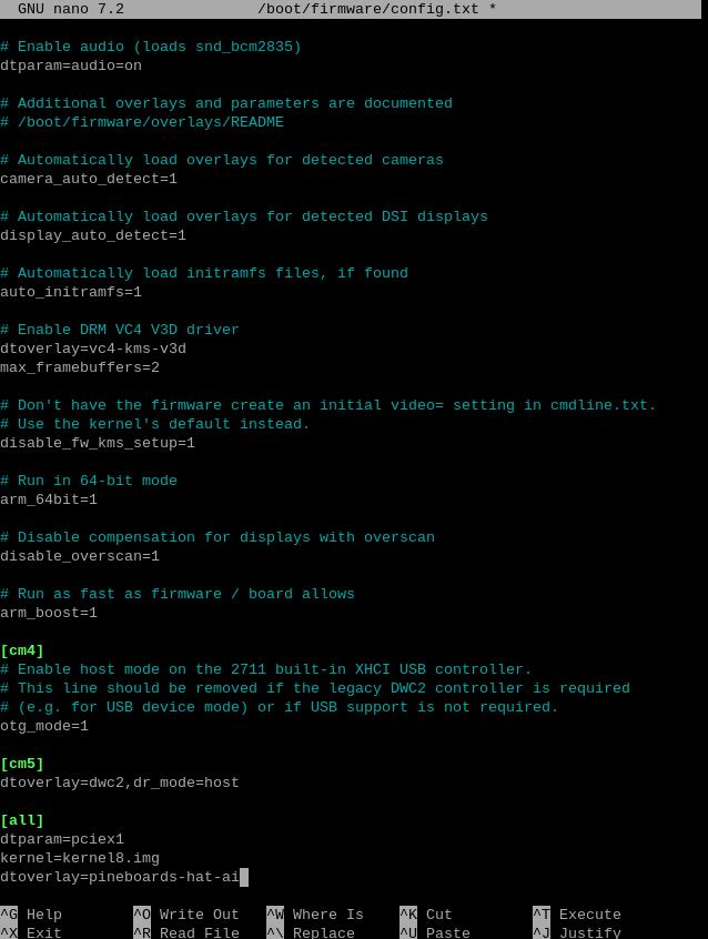
Then, save the file and reboot the system:
sudo reboot
4.2 Ensuring software environment
After reboot the system, open the Raspberry Pi terminal and enter the command:
uname -r
After ensuring the kernel version is greater than 4.18, enter:
lsmod | grep apex
Ensure there is no output, then you can begin installing the TPU driver.

4.3 Install necessary software
Ensure the network is connected to internet connection to the regions out of China (you may need to find your own method), and then add the Google TPU software library:
echo "deb https://packages.cloud.google.com/apt coral-edgetpu-stable main" | sudo tee /etc/apt/sources.list.d/coral-edgetpu.list
curl https://packages.cloud.google.com/apt/doc/apt-key.gpg | sudo apt-key add -

Update the software list after adding:
sudo apt-get update
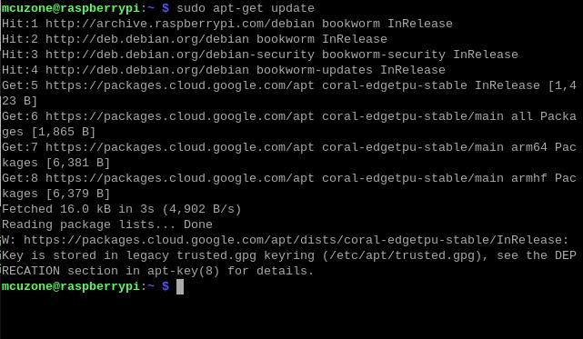
Install the necessary software after the update is completed:
sudo apt-get install cmake libedgetpu1-std devscripts debhelper dkms dh-dkms
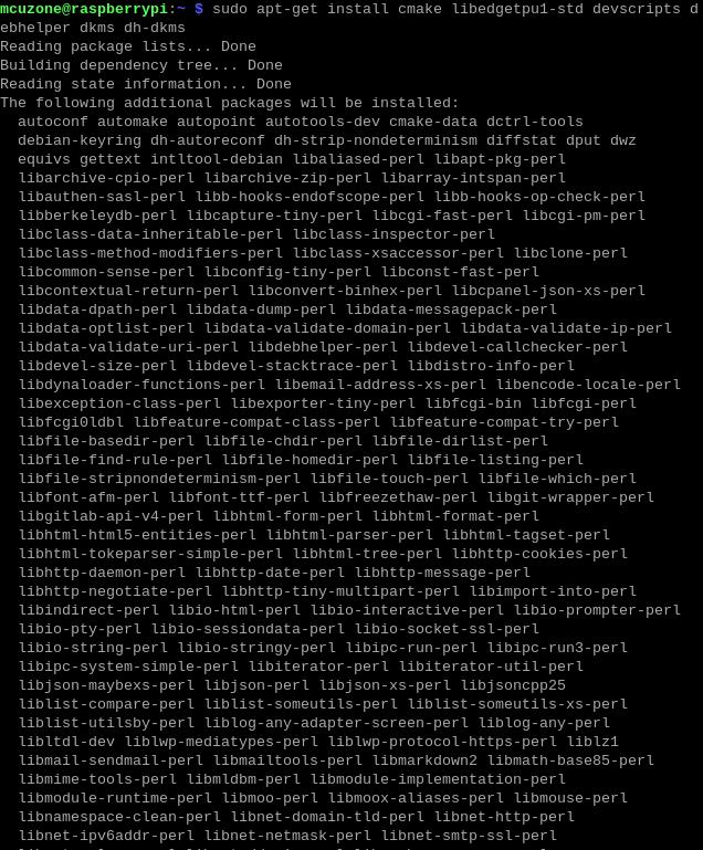

4.4 Install Gasket Driver
Enter the following commands in sequence to install the Gasket Driver:
git clone https://github.com/google/gasket-driver.git
cd gasket-driver
sudo debuild -us -uc -tc -b
cd ..
sudo dpkg -i gasket-dkms_1.0-18_all.deb

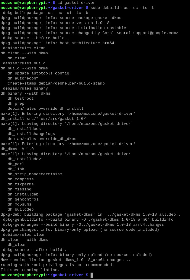
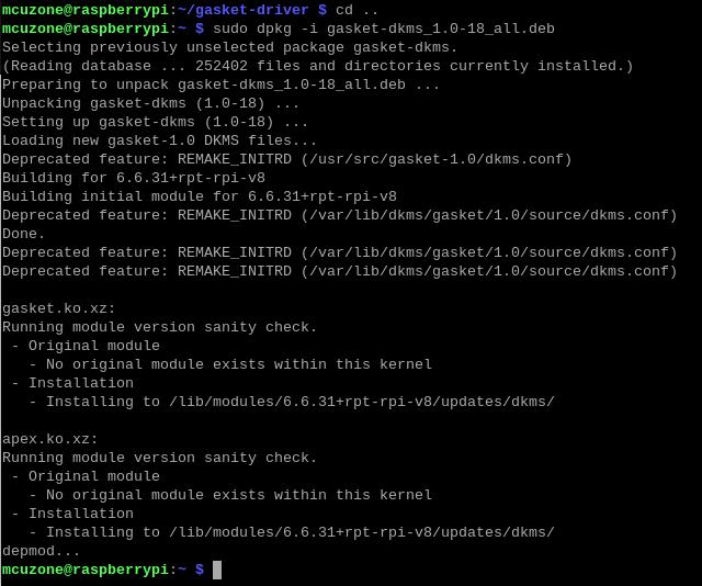
After the installation is complete, enter the following command to ensure that the driver and software were installed successfully:
sudo apt-get install gasket-dkms libedgetpu1-std

Then, add a udev rule to obtain device operation permissions:
sudo sh -c "echo 'SUBSYSTEM==\"apex\", MODE=\"0660\", GROUP=\"apex\"' >> /etc/udev/rules.d/65-apex.rules"
add user to apex:
sudo groupadd apex
sudo adduser $USER apex

Reboot the system after the setup is complete:
sudo reboot
4.5 Verification module testing and driver installation
After system starting, verification module testing and driver installation:
lspci -nn | grep 089a
ls /dev/apex_0

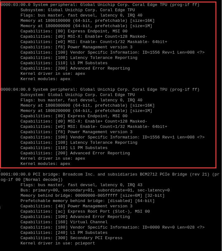
This board has a dual-TPU onboard, so you can see two TPU modules:
By entering sudo lspci -v, you can see the driver loading. There are also drivers for the two TPU modules.
4.6 Configuration of the Code Execution Environment
Running Google TPU module code requires Python versions between 3.6 and 3.9, while the latest Raspberry Pi system is Python 3.11. Therefore, we need to use Pyenv to download an older version of Python.
First, install the depends:
sudo apt-get install -y make build-essential libssl-dev zlib1g-dev \libbz2-dev libreadline-dev libsqlite3-dev wget curl llvm libncurses5-dev \libncursesw5-dev xz-utils tk-dev libffi-dev liblzma-dev python3-openssl

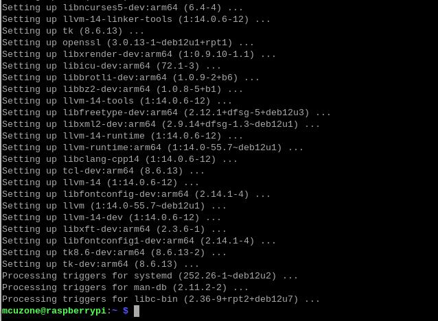
Install pyenv after the depends are installed:
curl https://pyenv.run | bash

Enter the command:
sudo nano ~/.bashrc
Or:
sudo mousepad ~/.bashrc
Add the codes in the ending of this file:
export PYENV_ROOT="$HOME/.pyenv"
[[ -d $PYENV_ROOT/bin ]] && export PATH="$PYENV_ROOT/bin:$PATH"
eval "$(pyenv init -)"

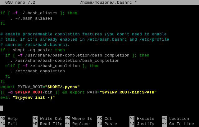
Save and exit after adding, then reload the shell:
exec "$SHELL"

Then, we can use pyenv to install an older version of Python:
pyenv install -v 3.8.8


After the installation is successful, we will change the system Python version to 3.8.8:
pyenv global 3.8.8
After the change is successful, you can check the current Python version is 3.8.8:
pyenv versions
python3 -V

4.7 Download the code and run the module
Enter the following commands in sequence to download:
mkdir coral && cd coral
git clone https://github.com/google-coral/pycoral.git
cd pycoral
cd test_data
git clone https://github.com/google-coral/test_data.git


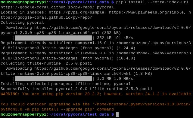
Then, download the code and run the module:
pip3 install numpy
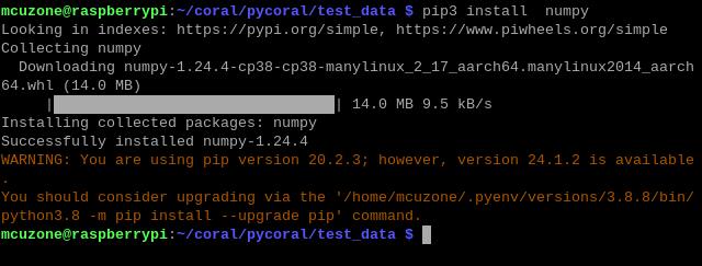
pip3 install Pillow

pip3 install --extra-index-url https://google-coral.github.io/py-repo/ pycoral
4.8 Run the code
4.8.1 Single-TPU running a single model
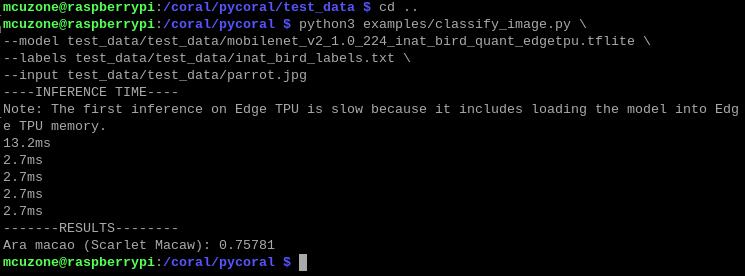
Enter the following code to run it:

Note: You can copy the following code, but please paste it into a text editor first. Then, following the format shown above, remove any extra enter. After that, copy it again and paste it into the terminal to run.
python3 examples/classify_image.py \
--model test_data/test_data/mobilenet_v2_1.0_224_inat_bird_quant_edgetpu.tflite \
--labels test_data/test_data/inat_bird_labels.txt \
--input test_data/test_data/parrot.jpg
4.8.2 Dul-TPU running multiple model
Enter the following code to run it:

Note: You can copy the following code, but please paste it into a text editor first. Then, following the format shown above, remove any extra enter. After that, copy it again and paste it into the terminal to run.
python3 examples/two_models_inference.py \
--classification_model test_data/mobilenet_v2_1.0_224_quant_edgetpu.tflite \
--detection_model \
test_data/ssd_mobilenet_v2_face_quant_postprocess_edgetpu.tflite \
--image test_data/parrot.jpg

4.8.3 Dul-TPU running a single model
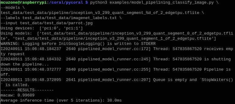
Enter the following code to run it:

Note: You can copy the following code, but please paste it into a text editor first. Then, following the format shown above, remove any extra enter. After that, copy it again and paste it into the terminal to run.
python3 examples/model_pipelining_classify_image.py \
--models \
test_data/pipeline/inception_v3_299_quant_segment_%d_of_2_edgetpu.tflite \
--labels test_data/imagenet_labels.txt \
--input test_data/parrot.jpg
You should downloading a large amount of data from the internet out of China to use the testing of this development board, so users can contact our company after buying this development board to obtain a pre-configured Raspberry Pi OS image.
V. E2PROM chip flashing operation demonstration
5.1 Overview
The MPDTPU expansion board is equipped with an E2PROM chip. During the boot process, the Raspberry Pi system will search for the E2PROM via the I2C pins and read the E2PROM information. Therefore, we can write the information and device tree files we need into the E2PROM chip to achieve the functionality of automatic configuration loading.
Note: The operation requires a stable internet connection to the regions out of China (you may need to find your own method). Otherwise, many files may not download or may only partially download, which could ultimately lead to the code failing to run.
5.2 Enable I2C
Select the items in the order shown in the following diagram, enable I2C, and then restart the Raspberry Pi OS.
5.3 Install tools
Execute the following commands to install tools:
git clone https://github.com/raspberrypi/utils.git
cd utils/eeptools
cmake .
make
sudo make install
Download and put the i2c-gpio.dtbo file:
wget http://www.mcuzone.com/wiki/0025_MPDTPU/i2c-gpio.zip
unzip i2c-gpio.zip
sudo cp i2c-gpio.dtbo /boot/overlays
Reboot the system after completion:
sudo reboot
5.4 Edit the configuration file
Execute the following commands:
cd utils/eeptools
sudo mousepad eeprom_settings.txt

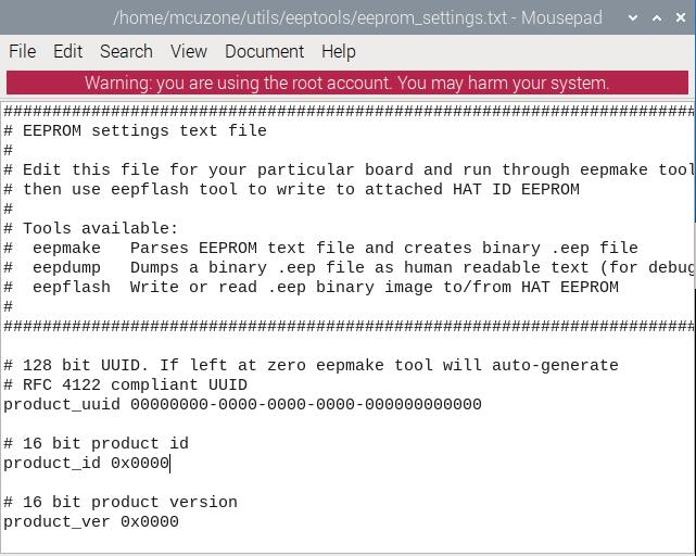
Copy all the content of the eeprom_settings.txt and then exit.
Then execute:
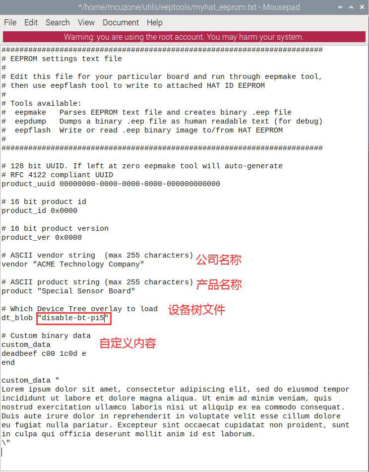
sudo mousepad myhat_eeprom.txt

Create a file named myhat_eeprom.txt, paste the text you just copied into it, and you can customize the content of the red section. In this demonstration, we will modify the device tree file to disable Bluetooth, which means changing the device tree to disable-bt-pi5. After making these changes, save the file and exit:
Then use the eepmake tool to generate the UUID:
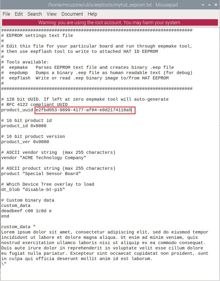
eepmake myhat_eeprom.txt myhat.eep

Modify the generated UUID in myhat_eeprom.txt, then save and exit:
Execute the following commands to enable I2C-9 and view the result:
sudo dtoverlay i2c-gpio i2c_gpio_sda=0 i2c_gpio_scl=1 bus=9
i2cdetect -y 9

Please modify the address within the eepflash.sh script so that it points to 0050:
sudo nano eepflash.sh

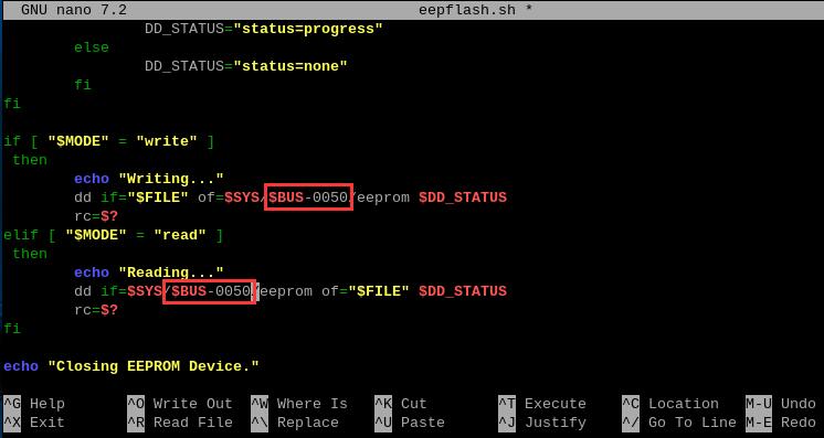
Then save and exit.
5.5 Programming the EEPROM
Execute the following command to program the EEPROM:
sudo ./eepflash.sh -w -t=24c32 -a=0x50 -f=myhat.eep

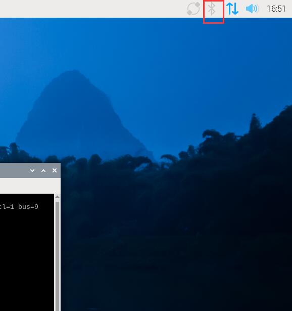
After programming is complete, reboot the system, and you will see that Bluetooth is disabled.
VI. Voltage and current monitoring function demonstration
The MPDTPU expansion board adds voltage and current detection functionality. Using this expansion board, you can monitor real-time voltage, current, and power data of the dual-TPU.
1. Follow Section 5.2 to enable I2C in the Raspberry Pi OS.
2. 执行下列命令,安装python库:
pip3 intsall smbus

3. 执行下列命令,下载监测软件:
wget http://www.mcuzone.com/wiki/0025_MPDTPU/INA219.zip
unzip INA219.zip
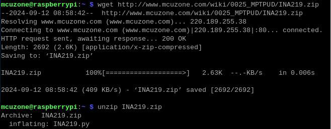
4. 运行监测软件:
python3 INA219.py
不插TPU模块:

插TPU模块静态:

单TPU运行:

双TPU同时运行:

在双TPU同时运行时,可以看到最大电流已经升至0.912A,对应约4.527W功率,双TPU同时工作时功率基本是单TPU工作的功率(最大电流0.524A,对应约2.603W功率)的大约两倍。
联系我们
电话:13957118045
如本页面有任何疏漏、错误或者侵权,请通过上述途径联系我们,谢谢!
Copyright 2004-2025 野芯科技


 QQ:8204136