1001 RPi0 4G CAT1-ETH(RS485 OPT:修订间差异
无编辑摘要 |
|||
| (未显示2个用户的64个中间版本) | |||
| 第1行: | 第1行: | ||
[[1001 RPi0 4G Cat1-ETH(百兆网络 4G Cat1 USB2.0-A 485版本可选)|切换语言为中文]] | |||
== '''Keywords''' == | == '''Keywords''' == | ||
Raspberry Pi, Raspberry Pi Zero, Cat1 4G LTE, USB2.0-A, Ethernet, Expansion Board, USB HUB | Raspberry Pi Zero,Raspberry Pi Zero W,Raspberry Pi Zero WH,Raspberry Pi Zero 2 W, Cat1 4G LTE, USB2.0-A, Ethernet, Expansion Board, USB HUB, RS485, driver-free | ||
== ''' | == '''I. Introduction''' == | ||
The Raspberry Pi Zero series (including Zero, Zero W(H), and Zero 2W) is a | The Raspberry Pi Zero series (including Zero, Zero W(H), and Zero 2W) is a low cost-effective embedded system platform with a compact size, low power consumption, and decent performance, making it suitable for many lightweight application scenarios. The Zero series, despite its compact size, offers many expansion interfaces. The underside of the board features gold-plated test points for USB and power connections. These USB and power test points allow us to connect various types of peripherals for expansion. | ||
This expansion board is a USB hub, connecting the expansion board to the USB port of the Zero via pogo pins. It extends four USB ports through the USB connection: one USB port is converted to a 100Mbps wired Ethernet connection, one USB port is connected to a 4G Cat1 module, and two USB2.0-A host interfaces are provided. There is also an RS485 version available, which can convert one USB port to an RS485 interface. | |||
4G Cat1 is a cost-effective module designed for low-speed IoT applications around 10Mbps. The 10Mbps downlink and 5Mbps uplink speeds can meet the vast majority of networking and transmission needs.This module is plug-and-play on Raspberry Pi and Ubuntu OS, automatically recognized as a 4G connection without needing drivers or dial-up configurations, making it convenient for users to develop applications.It have two verison, CAT.1 and CAT.1-EU . | |||
2. | == '''II. Hardware Spec''' == | ||
2.1 One USB-C power input, similar to the micro USB PWR on the Raspberry Pi Zero; choose one of the two options. | |||
2. | 2.2 One 10/100Mbps Ethernet. | ||
2. | 2.3 One 4G LTE Cat1 module. | ||
2. | 2.4 One Nano SIM card and one IPEX-1 antenna. | ||
2. | 2.5 Two USB2.0-A HS. | ||
2. | 2.6 Four LEDs: PWR/MODE/ACT LED | ||
2. | 2.7 One reset button for 4G module. | ||
2. | 2.8 '''''The RS485 version with industrial-grade power isolation,''''' it is USB to RS485, so only one USB2.0 on board. | ||
2. | 2.9 Aluminum alloy enclosure(OPT). | ||
Note 1: After connecting this expansion board, the Micro USB port on the Zero will no longer be usable. | Note 1: After connecting this expansion board, the Micro USB port on the Zero will no longer be usable. | ||
| 第32行: | 第34行: | ||
Note 2: In some systems, it is necessary to disable the OTG function and set the USB mode to Host mode. | Note 2: In some systems, it is necessary to disable the OTG function and set the USB mode to Host mode. | ||
Note 3: The | Note 3: The board supports all versions of the Raspberry Pi Zero, including the Zero, Zero W, Zero WH, and Zero 2W. | ||
Note 4: The board supportsother Pi with USB contacts in the same position, such as the Orange Pi Zero 2W. | |||
http://www.mcuzone.com/wiki/0007_Zero_4G_Cat1/ | http://www.mcuzone.com/wiki/0007_Zero_4G_Cat1/0007_Zero_4G_Cat1_78.jpg | ||
http://www.mcuzone.com/wiki/0007_Zero_4G_Cat1/ | http://www.mcuzone.com/wiki/0007_Zero_4G_Cat1/0007_Zero_4G_Cat1_79.jpg | ||
http://www.mcuzone.com/wiki/0007_Zero_4G_Cat1/ | http://www.mcuzone.com/wiki/0007_Zero_4G_Cat1/0007_Zero_4G_Cat1_80.jpg | ||
http://www.mcuzone.com/wiki/0007_Zero_4G_Cat1/0007_Zero_4G_Cat1_81.jpg | |||
http://www.mcuzone.com/wiki/0007_Zero_4G_Cat1/0007_Zero_4G_Cat1_82.jpg | |||
http://www.mcuzone.com/wiki/0007_Zero_4G_Cat1/0007_Zero_4G_Cat1_83.jpg | |||
{| class="wikitable" | |||
|+4G Parameters | |||
!model | |||
!CAT1 | |||
!CAT1-EU | |||
|- | |||
| rowspan="2" |Band | |||
|FDD:B1/B3/B5/B8 | |||
|FDD:B1/B3/B5/B7/B8/B20/28 | |||
|- | |||
|TDD:B34/B38/B39/B40/B41 | |||
|TDD:B38/B40/B41 | |||
|- | |||
|DATA | |||
| colspan="2" |FDD: Max 10Mbps(DL)/Max 5Mbps(UL) | |||
TDD:Max 8Mbps(DL)/Max 2Mbps(UL) | |||
Max 6Mbps(DL)/Max 4Mbps(UL) | |||
|} | |||
== '''III. Work with Raspberry Pi OS''' == | |||
We conducted tests based on the Raspberry Pi Zero 2W. | |||
The Raspberry Pi OS:(Raspberry Pi OS with desktop) 2024-07-04-raspios-bookworm-arm64.img.xz. | |||
You can download the Raspberry Pi OS in: | |||
https://www.raspberrypi.com/software/operating-systems/#raspberry-pi-os-64-bit | |||
(If you are using the Raspberry Pi Zero (1st generation) series boards, they only support 32-bit systems. Please be sure to download the correct version.) | |||
=== | === 3.1 View hardware devices === | ||
==== | ==== 3.1.1 View USB devices ==== | ||
Open the terminal in Raspberry Pi OS and enter the command<code>lsusb</code>, as shown in the image below: | Open the terminal in Raspberry Pi OS and enter the command<code>lsusb</code>, as shown in the image below: | ||
'''RPi0_RS485CAT1:''' | |||
http://www.mcuzone.com/wiki/0007_Zero_4G_Cat1/0007_Zero_4G_Cat1_86.jpg | |||
'''RPi0_RS485CAT1EU:''' | |||
http://www.mcuzone.com/wiki/0007_Zero_4G_Cat1/0007_Zero_4G_Cat1_87.jpg | |||
'''RPi0_CAT1-ETH/RPi0_CAT1-EU_ETH:''' | |||
http://www.mcuzone.com/wiki/0007_Zero_4G_Cat1/0007_Zero_4G_Cat1_88.jpg | |||
If the system stop at the Raspberry Pi logo and fails to boot: | |||
http://www.mcuzone.com/wiki/0007_Zero_4G_Cat1/0007_Zero_4G_Cat1_58.jpg | |||
or if after booting, the keyboard, mouse, and 4G module cannot be used, please carefully check whether the pogo pins are aligned with the gold-plated contacts. Additionally, on the PC, open the <code>config.txt</code> file located in the root directory of the TF card to check the USB initialization script. | |||
http://www.mcuzone.com/wiki/0007_Zero_4G_Cat1/0007_Zero_4G_Cat1_41.jpg | http://www.mcuzone.com/wiki/0007_Zero_4G_Cat1/0007_Zero_4G_Cat1_41.jpg | ||
You need to confirm that the three red-boxed areas in the following image are all configured completely. If not, please manually add the missing parts and save the file: | |||
<code># otg_mode=1</code> (It is recommended to comment out as follow) | |||
<code> | <code>dtoverlay=dwc2,dr_mode=host</code> (These two areas must be ensured to be included.) | ||
http://www.mcuzone.com/wiki/0007_Zero_4G_Cat1/0007_Zero_4G_Cat1_57.jpg | |||
==== 3.1.2 View network devices ==== | |||
The 4G module is automatically recognized in the Raspberry Pi OS, requires no drivers, and is plug-and-play. | |||
Open the terminal in Raspberry Pi OS and enter the command <code>ifconfig -a</code>, as shown in the image below: | Open the terminal in Raspberry Pi OS and enter the command <code>ifconfig -a</code>, as shown in the image below: | ||
http://www.mcuzone.com/wiki/0007_Zero_4G_Cat1/0007_Zero_4G_Cat1_24.jpg | http://www.mcuzone.com/wiki/0007_Zero_4G_Cat1/0007_Zero_4G_Cat1_24.jpg | ||
We can see that eth0 is a USB-to-Ethernet | We can see that eth0 is a USB-to-Ethernet, and eth1 is a 4G Cat1 connection (with the IP address in the image above is 192.168.5.8). | ||
=== | === 3.2 Test network devices === | ||
==== | ==== 3.2.1 ping tests ==== | ||
When testing, there is a priority order: if eth0 is connected, it will be used first. If there are specific requirements for internal and external networks, please adjust the metric values of each network and the DNS server settings. | When testing, there is a priority order: if eth0 is connected, it will be used first. If there are specific requirements for internal and external networks, please adjust the metric values of each network and the DNS server settings. | ||
| 第124行: | 第147行: | ||
<code>sudo ifconfig eth0 up</code> | <code>sudo ifconfig eth0 up</code> | ||
==== | ==== 3.2.2 Set network adapter priority ==== | ||
To set the priority of network cards, you need to modify the metric value of the network card. First, we need to install the ifmetric software. | To set the priority of network cards, you need to modify the metric value of the network card. First, we need to install the ifmetric software. | ||
| 第163行: | 第186行: | ||
Check if the current nameserver is correct. If it is not, please change it to the nameserver of the network card with higher priority or to some common nameserver addresses (such as 8.8.8.8, etc.). | Check if the current nameserver is correct. If it is not, please change it to the nameserver of the network card with higher priority or to some common nameserver addresses (such as 8.8.8.8, etc.). | ||
==== | ==== 3.2.3 Using udhcpc to specify DNS servers ==== | ||
In the previous section, we discussed specifying DNS servers by modifying the nameserver. In fact, we can also achieve this by using udhcpc. | In the previous section, we discussed specifying DNS servers by modifying the nameserver. In fact, we can also achieve this by using udhcpc. | ||
| 第184行: | 第207行: | ||
http://www.mcuzone.com/wiki/0007_Zero_4G_Cat1/0007_Zero_4G_Cat1_50.jpg | http://www.mcuzone.com/wiki/0007_Zero_4G_Cat1/0007_Zero_4G_Cat1_50.jpg | ||
==== | ==== 3.2.4 Examples of how to use udhcpc ==== | ||
Example 1: The 100Mbps Ethernet port is connected to the Internet, and the 4G Cat1 is connected normally. In this case, if we ping a certain domain name, it will succeed: | Example 1: The 100Mbps Ethernet port is connected to the Internet, and the 4G Cat1 is connected normally. In this case, if we ping a certain domain name, it will succeed: | ||
| 第205行: | 第228行: | ||
http://www.mcuzone.com/wiki/0007_Zero_4G_Cat1/0007_Zero_4G_Cat1_55.jpg | http://www.mcuzone.com/wiki/0007_Zero_4G_Cat1/0007_Zero_4G_Cat1_55.jpg | ||
==== | ==== 3.2.5 Test speed by iperf3 ==== | ||
You can download iperf3 (Windows version) in: | You can download iperf3 (Windows version) in: | ||
| 第224行: | 第247行: | ||
4G CAT1 speed test results: | 4G CAT1 speed test results: | ||
http://www.mcuzone.com/wiki/0007_Zero_4G_Cat1/ | http://www.mcuzone.com/wiki/0007_Zero_4G_Cat1/0007_Zero_4G_Cat1_66.jpg | ||
'''''Note: Network speed tests are affected by network conditions and testing methods. The actual speed may vary; this test is for reference only.''''' | '''''Note: Network speed tests are affected by network conditions and testing methods. The actual speed may vary; this test is for reference only.''''' | ||
== | === 3.3 AT Command for 4G Cat1 Module === | ||
==== | ==== 3.3.1 Open AT Command serial port ==== | ||
To operate 4G Cat1 Module using AT commands on a Raspberry Pi, you first need to open the AT command serial port. The method to open it is as follows: | |||
Input the following command: <code>lsusb</code>, to open ttyUSB serial port: | |||
If you use '''RPi0_RS485CAT1''': | |||
http://www.mcuzone.com/wiki/0007_Zero_4G_Cat1/0007_Zero_4G_Cat1_23.jpg | http://www.mcuzone.com/wiki/0007_Zero_4G_Cat1/0007_Zero_4G_Cat1_23.jpg | ||
Record the ID value of the 4G module: 1782 4e00 | |||
Use the following command to open the ttyUSB serial port, where the value after echo is the ID recorded above: | |||
<code>sudo modprobe option</code> | <code>sudo modprobe option</code> | ||
| 第247行: | 第272行: | ||
http://www.mcuzone.com/wiki/0007_Zero_4G_Cat1/0007_Zero_4G_Cat1_12.jpg | http://www.mcuzone.com/wiki/0007_Zero_4G_Cat1/0007_Zero_4G_Cat1_12.jpg | ||
If you use '''RPi0_RS485CAT1EU, RPi0_CAT1-ETH, RPi0_CAT1-EU_ETH''': | |||
http://www.mcuzone.com/wiki/0007_Zero_4G_Cat1/0007_Zero_4G_Cat1_68.jpg | |||
Record the ID value of the 4G module: 19d1 0001 | |||
Use the following command to open the ttyUSB serial port, where the value after echo is the ID recorded above: | |||
<code>sudo modprobe option</code> | |||
<code>sudo sh -c 'echo 19d1 0001 > /sys/bus/usb-serial/drivers/option1/new_id'</code> | |||
http://www.mcuzone.com/wiki/0007_Zero_4G_Cat1/0007_Zero_4G_Cat1_69.jpg | |||
After execution is complete, the system should have three additional devices: ttyUSB0, ttyUSB1, and ttyUSB2. | |||
Then Open serial port by serial port tool. | |||
Install minicom: | |||
<code>sudo apt-get install minicom</code> | <code>sudo apt-get install minicom</code> | ||
| 第256行: | 第296行: | ||
http://www.mcuzone.com/wiki/0007_Zero_4G_Cat1/0007_Zero_4G_Cat1_13.jpg | http://www.mcuzone.com/wiki/0007_Zero_4G_Cat1/0007_Zero_4G_Cat1_13.jpg | ||
Open AT Command serial port by minicom: | |||
<code>sudo minicom -D /dev/ttyUSB0</code> | <code>sudo minicom -D /dev/ttyUSB0</code> | ||
Or | |||
<code>sudo minicom -D /dev/ttyUSB1</code> | <code>sudo minicom -D /dev/ttyUSB1</code> | ||
| 第266行: | 第306行: | ||
http://www.mcuzone.com/wiki/0007_Zero_4G_Cat1/0007_Zero_4G_Cat1_14.jpg | http://www.mcuzone.com/wiki/0007_Zero_4G_Cat1/0007_Zero_4G_Cat1_14.jpg | ||
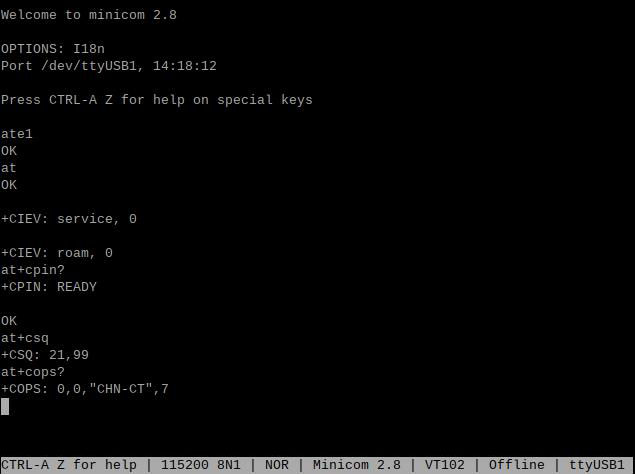
Then directly type the AT command and press Enter to see the result. If you need to view the echo, please type the command: <code>ate1.</code> | |||
Note: The model of the 4G module may change, but the process remains the same. You only need to use <code>lsusb</code> to check the actual USB ID and replace it with the actual value in subsequent commands. Additionally, some 4G Cat1 modules's chipset IDs have already been included in the kernel's supported list, so these Cat1 modules can be automatically recognized as ttyAMAx without the need to add a USB ID. | |||
=== | ==== 3.3.2 Common AT commands ==== | ||
1) | 1) Check if the SIM card is detected: | ||
<code>at+cpin?</code> | <code>at+cpin?</code> | ||
Return ready to indicate the card has been recognized, if return error, you need to check the hardware. | |||
2) | 2) Check antenna signal quality: | ||
<code>at+csq</code> | <code>at+csq</code> | ||
Return values between 26 and 31 indicate a good signal, with 31 representing a full signal strength; return values between 20 and 25 indicate a barely acceptable signal; return values below 20 indicate a poor signal or that the antenna might not be connected. | |||
3) | 3) Check network registration status: | ||
<code>at+cops?</code> | <code>at+cops?</code> | ||
Normally, it should return the network supporter's code: 7, where 7 represents 4G. | |||
Note: The above command <code>at+csq</code> should not include a question mark, while the other two commands require a question mark. | |||
4) | 4) View the SIM card's IMEI code: | ||
<code>at+cgsn</code> | <code>at+cgsn</code> | ||
5) | 5) Reset 4G module (Sometimes, if you reinsert the SIM card, hot swapping may not work; in such cases, you can use this reset command to reset the module.): | ||
<code>at+reset</code> | <code>at+reset</code> | ||
6) | 6) Disable radio frequency: | ||
<code>at+cfun=0</code> | <code>at+cfun=0</code> | ||
Enable radio frequency: | |||
<code>at+cfun=1</code> | <code>at+cfun=1</code> | ||
The two commands mentioned above can be used in pairs to allow the module to re-register with the network without restarting the 4G module. | |||
http://www.mcuzone.com/wiki/0007_Zero_4G_Cat1/0007_Zero_4G_Cat1_15.jpg | http://www.mcuzone.com/wiki/0007_Zero_4G_Cat1/0007_Zero_4G_Cat1_15.jpg | ||
== ''' | === 3.4 RS485 serial test === | ||
If you are using '''''the RS485 version''''', it has one fewer USB2.0-A host interface, which is replaced by an RS485 interface. | |||
=== | First, you need to install the serial port software CuteCom; the installation command is: | ||
Ubuntu | |||
<code>sudo apt install cutecom</code> | |||
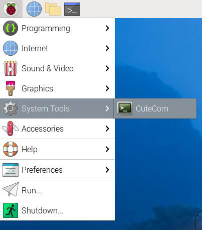
After installation, click on the Raspberry Pi icon in the top left corner of the desktop, and under "System Tools," there will be a shortcut to CuteCom: | |||
http://www.mcuzone.com/wiki/0012_MPUUART_MP4232/0012_MPUUART_MP4232_01.jpg | |||
If there are permission issues during use, please open the Raspberry Pi OS terminal and enter: | |||
<code>sudo cutecom</code> | |||
to run the CuteCom. | |||
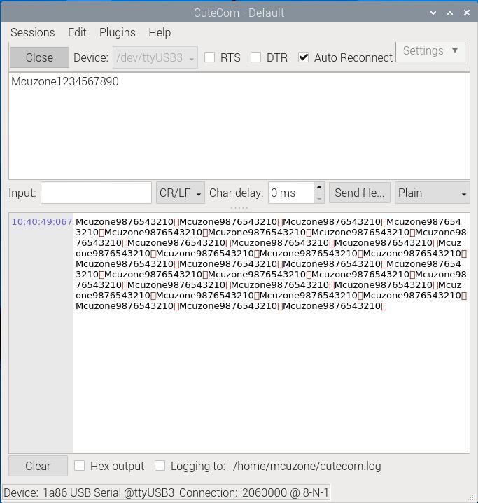
This expansion board comes with a 4G module, which occupies three serial ports ttyUSB0-2. Therefore, the serial port number for the RS485 serial port is shifted to ttyUSB3. | |||
Plug a USB to RS485 converter into the PC and connect it to the RS485 port on the expansion board. Open the serial port software on each end for transmission and reception. The result is as follows: | |||
Raspberry Pi OS: | |||
http://www.mcuzone.com/wiki/0007_Zero_4G_Cat1/0007_Zero_4G_Cat1_61.jpg | |||
Windows: | |||
http://www.mcuzone.com/wiki/0007_Zero_4G_Cat1/0007_Zero_4G_Cat1_62.jpg | |||
Through practical testing, the baud rate can reach up to 2.06M (based on the criterion that transmitted data does not become garbled). | |||
== '''IV. Work with Ubuntu OS''' == | |||
The hardware in this document is based on the Raspberry Pi Zero 2W. | |||
Ubuntu system: Ubuntu Server 24.04 LTS. (The Raspberry Pi Zero 2W cannot use the Desktop version due to performance limitations.) | |||
The image is: ubuntu-24.04-preinstalled-server-arm64+raspi.img.xz | |||
You can download the Ubuntu system in: | |||
https://ubuntu.com/download/raspberry-pi | |||
=== 4.1 Edit the initialization script === | |||
After flashing Ubuntu Server, please open the <code>config.txt</code> file located in the root directory of the system partition on the TF card on your PC to check the initialization script for USB. Ubuntu Server initializes the USB twice, but the first initialization does not configure it in host mode. Please verify that the area highlighted in red in the following image is configured properly. If it is not, please manually add the complete configuration: | |||
<code>dtoverlay=dwc2,dr_mode=host</code> | <code>dtoverlay=dwc2,dr_mode=host</code> | ||
| 第320行: | 第400行: | ||
http://www.mcuzone.com/wiki/0007_Zero_4G_Cat1/0007_Zero_4G_Cat1_32.jpg | http://www.mcuzone.com/wiki/0007_Zero_4G_Cat1/0007_Zero_4G_Cat1_32.jpg | ||
http://www.mcuzone.com/wiki/0007_Zero_4G_Cat1/ | http://www.mcuzone.com/wiki/0007_Zero_4G_Cat1/0007_Zero_4G_Cat1_75.jpg | ||
=== | === 4.2 Configure username and password === | ||
Insert the TF card into Zero 2W and boot up the system. Upon the first startup, you will be prompted to log in; both the username and password are "ubuntu." After logging in successfully, you will be asked to change the password. | |||
http://www.mcuzone.com/wiki/0007_Zero_4G_Cat1/0007_Zero_4G_Cat1_31.jpg | http://www.mcuzone.com/wiki/0007_Zero_4G_Cat1/0007_Zero_4G_Cat1_31.jpg | ||
Once the password is changed, you will automatically enter the system. | |||
=== | === 4.3 Configure network === | ||
After system startup, there is no network available, and further configuration is needed before it can be used. | |||
''''' | '''''Note: the system does not integrate the ifconfig tool by default; only the ip command is available.''''' | ||
Execute <code>ip addr</code> to view and record the name of the network interface card: | |||
http://www.mcuzone.com/wiki/0007_Zero_4G_Cat1/0007_Zero_4G_Cat1_33.jpg | http://www.mcuzone.com/wiki/0007_Zero_4G_Cat1/0007_Zero_4G_Cat1_33.jpg | ||
The second network interface card (enx00e0996df1cd) is a USB-to-100Mbps Ethernet adapter, and the third network interface card (enxac4bb3b9ebe5) is the 4G module. | |||
Then run the following command to open the network interface card configuration file: | |||
<code>sudo nano /etc/netplan/50-cloud-init.yaml</code> | <code>sudo nano /etc/netplan/50-cloud-init.yaml</code> | ||
Edit the network interface card configuration file according to the diagram below: | |||
http://www.mcuzone.com/wiki/0007_Zero_4G_Cat1/0007_Zero_4G_Cat1_34.jpg | http://www.mcuzone.com/wiki/0007_Zero_4G_Cat1/0007_Zero_4G_Cat1_34.jpg | ||
Save and exit, then reset the system. | |||
After rebooting, you can connect to the network. Install the <code>net-tools</code> to facilitate usage: | |||
<code>sudo apt install net-tools</code> | <code>sudo apt install net-tools</code> | ||
| 第356行: | 第436行: | ||
http://www.mcuzone.com/wiki/0007_Zero_4G_Cat1/0007_Zero_4G_Cat1_35.jpg | http://www.mcuzone.com/wiki/0007_Zero_4G_Cat1/0007_Zero_4G_Cat1_35.jpg | ||
=== | === 4.4 Test network and 4G module === | ||
Run the command <code>ifconfig -a</code> to view the information of network: | |||
http://www.mcuzone.com/wiki/0007_Zero_4G_Cat1/0007_Zero_4G_Cat1_36.jpg | http://www.mcuzone.com/wiki/0007_Zero_4G_Cat1/0007_Zero_4G_Cat1_36.jpg | ||
The first network interface card is a USB-to-100Mbps Ethernet adapter, and the second network interface card is the 4G module. | |||
By using the -I parameter, you can specify the network interface name when sending ping packets, thus determining which interface to use for the ping. Through ping tests to Tencent's website using these two network interfaces, we can know that the second network interface (4G module) supports IPv6: | |||
http://www.mcuzone.com/wiki/0007_Zero_4G_Cat1/0007_Zero_4G_Cat1_37.jpg | http://www.mcuzone.com/wiki/0007_Zero_4G_Cat1/0007_Zero_4G_Cat1_37.jpg | ||
=== | === 4.5 AT command interaction test === | ||
Install minicom: | |||
<code>sudo apt-get install minicom</code> | <code>sudo apt-get install minicom</code> | ||
| 第374行: | 第454行: | ||
http://www.mcuzone.com/wiki/0007_Zero_4G_Cat1/0007_Zero_4G_Cat1_38.jpg | http://www.mcuzone.com/wiki/0007_Zero_4G_Cat1/0007_Zero_4G_Cat1_38.jpg | ||
Open AT Command serial port by minicom: | |||
<code>sudo minicom -D /dev/ttyUSB0</code> | <code>sudo minicom -D /dev/ttyUSB0</code> | ||
Or | |||
<code>sudo minicom -D /dev/ttyUSB1</code> | <code>sudo minicom -D /dev/ttyUSB1</code> | ||
| 第384行: | 第464行: | ||
http://www.mcuzone.com/wiki/0007_Zero_4G_Cat1/0007_Zero_4G_Cat1_39.jpg | http://www.mcuzone.com/wiki/0007_Zero_4G_Cat1/0007_Zero_4G_Cat1_39.jpg | ||
Now you can use common AT commands for interaction: | |||
http://www.mcuzone.com/wiki/0007_Zero_4G_Cat1/0007_Zero_4G_Cat1_40.jpg | http://www.mcuzone.com/wiki/0007_Zero_4G_Cat1/0007_Zero_4G_Cat1_40.jpg | ||
== | === 4.6 RS485 serial test === | ||
This expansion board comes with a 4G module, which occupies three serial ports ttyUSB0-2. Therefore, the serial port number for the RS485 serial port is shifted to ttyUSB3. | |||
Plug a USB to RS485 converter into the PC and connect it to the RS485 port on the expansion board. Open the serial port software on each end for transmission and reception. We use minicom on Ubuntu system: | |||
<code>sudo minicom -D /dev/ttyUSB3</code> | |||
Through practical testing, the baud rate can reach up to 2.00M (based on the criterion that transmitted data does not become garbled). | |||
Ubuntu system: | |||
http://www.mcuzone.com/wiki/0007_Zero_4G_Cat1/0007_Zero_4G_Cat1_63.jpg | |||
Windows: | |||
http://www.mcuzone.com/wiki/0007_Zero_4G_Cat1/0007_Zero_4G_Cat1_64.jpg | |||
== | == '''V. Work with OpenWrt''' == | ||
=== 5.1 Overview === | |||
This expansion board, when paired with the Raspberry Pi Zero 2W running OpenWrt, can be configured as a one-in-one-out switch mode. The 4G module on the expansion board can serve as the WAN port (for direct 4G internet access), while the Ethernet port is configured as the LAN port for connecting to a PC. | |||
=== 5.2 Preparation === | |||
The OpenWrt which be used in this document is: openwrt-bcm27xx-bcm2709-rpi-2-squashfs-sysupgrade-linux-6.1.98-20240723.img.gz | |||
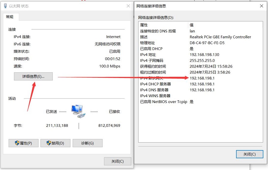
After flashing the OpenWrt system and powering it up, we connect an Ethernet cable from the Raspberry Pi's built-in Ethernet port to the PC's Ethernet port. Once the connection between the PC's network card and the Raspberry Pi's Ethernet port is successful, we find Network and Internet settings in Windows, then open the connected network under Ethernet to view the default gateway IP address. This address is the backend configuration page address for the OpenWrt system. As shown in the figure, the address for this test is 192.168.198.1: | |||
http://www.mcuzone.com/wiki/0007_Zero_4G_Cat1/ | http://www.mcuzone.com/wiki/0007_Zero_4G_Cat1/0007_Zero_4G_Cat1_18.jpg | ||
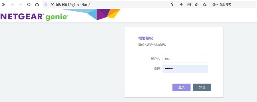
Then open a web browser and enter 192.168.198.1 to access the OpenWrt system. The default username is <code>root</code>, and the default password is <code>password</code>. | |||
http://www.mcuzone.com/wiki/0007_Zero_4G_Cat1/0007_Zero_4G_Cat1_19.jpg | |||
=== 5.3 Configure the OpenWrt system === | |||
After entering the OpenWrt system, connect the Raspberry Pi's Ethernet port directly to the PC's Ethernet port using an Ethernet cable. Once the PC's network card has acquired an IP address, the PC can directly access the internet through the 4G module (no additional settings required). | |||
=== | === 5.4 Test the network speed of 4G module === | ||
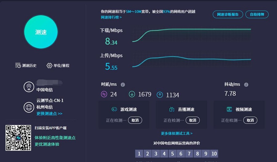
On the PC, open https://www.speedtest.cn/ to perform a speed test. At this point, the traffic goes through the 4G module, and the test results are as follows: | |||
http://www.mcuzone.com/wiki/0007_Zero_4G_Cat1/ | http://www.mcuzone.com/wiki/0007_Zero_4G_Cat1/0007_Zero_4G_Cat1_46.jpg | ||
'''''Note: The speed of 4G network testing is influenced by network signal strength and the testing method, so actual speeds may vary.''''' | |||
=== 5.5 Mounting USB drive and file operations === | |||
When you insert a USB drive into a USB port, you can directly see the information and mounting status of the USB drive in "System - Disk Management": | |||
http://www.mcuzone.com/wiki/0007_Zero_4G_Cat1/0007_Zero_4G_Cat1_20.jpg | |||
In the "System - Mount Points" section, you can see the status of all mount points and can configure them on this page. | |||
In the "Network Storage - File Assistant" section, you can perform operations on files within the system. | |||
http://www.mcuzone.com/wiki/ | http://www.mcuzone.com/wiki/0007_Zero_4G_Cat1/0007_Zero_4G_Cat1_21.jpg | ||
=== 5.6 TTYD terminal === | |||
The OpenWrt system comes with a web-based TTYD terminal, which can be accessed in the "System - TTYD Terminal" section. The default username is <code>root</code>, and the default password is <code>password</code>. Since you log in with the root account, you will have root privileges upon logging in. | |||
http://www.mcuzone.com/wiki/0007_Zero_4G_Cat1/0007_Zero_4G_Cat1_22.jpg | |||
== '''VI. Expansion board selection guide''' == | |||
http://www.mcuzone.com/wiki/1006_RPi0_4G_MiniPCIe/1006_RPi0_4G_MiniPCIe_65.jpg | |||
{{Contact_Us_icon}} | |||
[http://wiki.mcuzone.com/index.php?title=1001_RPi0_4G_Cat1-ETH(100M_ETH_4G_Cat1_USB2.0-A_RS485_version_optional) T] | |||
2025年3月5日 (三) 12:02的最新版本
Keywords
Raspberry Pi Zero,Raspberry Pi Zero W,Raspberry Pi Zero WH,Raspberry Pi Zero 2 W, Cat1 4G LTE, USB2.0-A, Ethernet, Expansion Board, USB HUB, RS485, driver-free
I. Introduction
The Raspberry Pi Zero series (including Zero, Zero W(H), and Zero 2W) is a low cost-effective embedded system platform with a compact size, low power consumption, and decent performance, making it suitable for many lightweight application scenarios. The Zero series, despite its compact size, offers many expansion interfaces. The underside of the board features gold-plated test points for USB and power connections. These USB and power test points allow us to connect various types of peripherals for expansion.
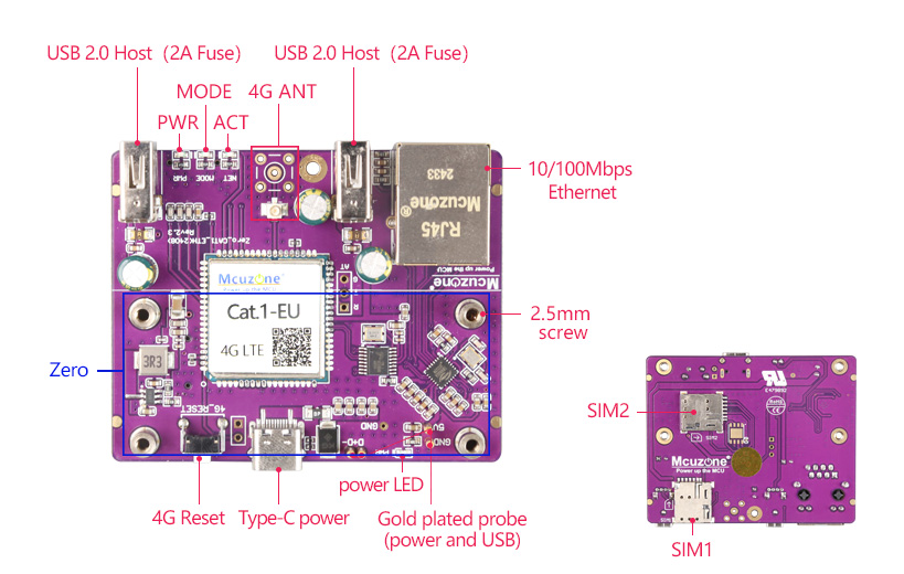
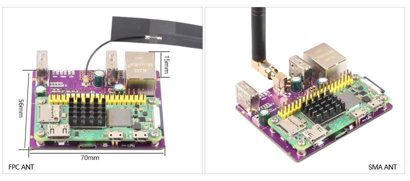
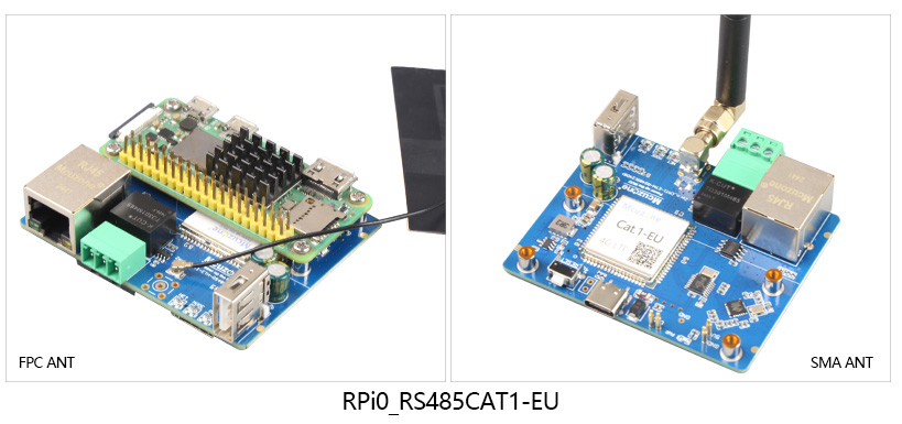
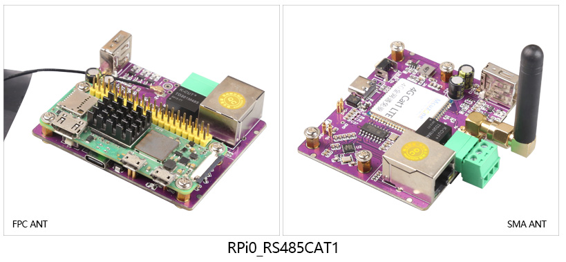
This expansion board is a USB hub, connecting the expansion board to the USB port of the Zero via pogo pins. It extends four USB ports through the USB connection: one USB port is converted to a 100Mbps wired Ethernet connection, one USB port is connected to a 4G Cat1 module, and two USB2.0-A host interfaces are provided. There is also an RS485 version available, which can convert one USB port to an RS485 interface.
4G Cat1 is a cost-effective module designed for low-speed IoT applications around 10Mbps. The 10Mbps downlink and 5Mbps uplink speeds can meet the vast majority of networking and transmission needs.This module is plug-and-play on Raspberry Pi and Ubuntu OS, automatically recognized as a 4G connection without needing drivers or dial-up configurations, making it convenient for users to develop applications.It have two verison, CAT.1 and CAT.1-EU .
II. Hardware Spec
2.1 One USB-C power input, similar to the micro USB PWR on the Raspberry Pi Zero; choose one of the two options.
2.2 One 10/100Mbps Ethernet.
2.3 One 4G LTE Cat1 module.
2.4 One Nano SIM card and one IPEX-1 antenna.
2.5 Two USB2.0-A HS.
2.6 Four LEDs: PWR/MODE/ACT LED
2.7 One reset button for 4G module.
2.8 The RS485 version with industrial-grade power isolation, it is USB to RS485, so only one USB2.0 on board.
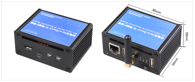
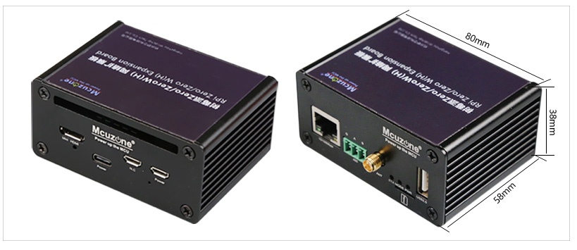
2.9 Aluminum alloy enclosure(OPT).
Note 1: After connecting this expansion board, the Micro USB port on the Zero will no longer be usable.
Note 2: In some systems, it is necessary to disable the OTG function and set the USB mode to Host mode.
Note 3: The board supports all versions of the Raspberry Pi Zero, including the Zero, Zero W, Zero WH, and Zero 2W.
Note 4: The board supportsother Pi with USB contacts in the same position, such as the Orange Pi Zero 2W.
| model | CAT1 | CAT1-EU |
|---|---|---|
| Band | FDD:B1/B3/B5/B8 | FDD:B1/B3/B5/B7/B8/B20/28 |
| TDD:B34/B38/B39/B40/B41 | TDD:B38/B40/B41 | |
| DATA | FDD: Max 10Mbps(DL)/Max 5Mbps(UL)
TDD:Max 8Mbps(DL)/Max 2Mbps(UL) Max 6Mbps(DL)/Max 4Mbps(UL) | |
III. Work with Raspberry Pi OS
We conducted tests based on the Raspberry Pi Zero 2W.
The Raspberry Pi OS:(Raspberry Pi OS with desktop) 2024-07-04-raspios-bookworm-arm64.img.xz.
You can download the Raspberry Pi OS in:
https://www.raspberrypi.com/software/operating-systems/#raspberry-pi-os-64-bit
(If you are using the Raspberry Pi Zero (1st generation) series boards, they only support 32-bit systems. Please be sure to download the correct version.)
3.1 View hardware devices
3.1.1 View USB devices
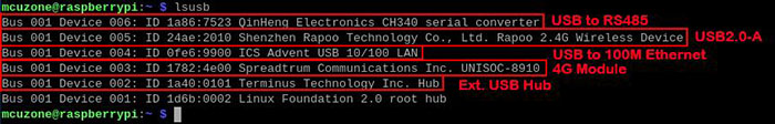
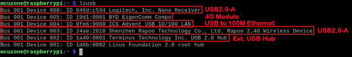
Open the terminal in Raspberry Pi OS and enter the commandlsusb, as shown in the image below:
RPi0_RS485CAT1:
RPi0_RS485CAT1EU:
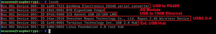
RPi0_CAT1-ETH/RPi0_CAT1-EU_ETH:
If the system stop at the Raspberry Pi logo and fails to boot:
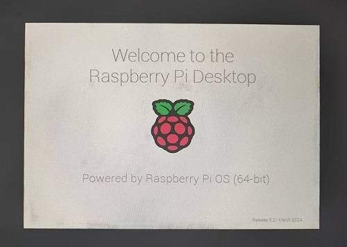
or if after booting, the keyboard, mouse, and 4G module cannot be used, please carefully check whether the pogo pins are aligned with the gold-plated contacts. Additionally, on the PC, open the config.txt file located in the root directory of the TF card to check the USB initialization script.
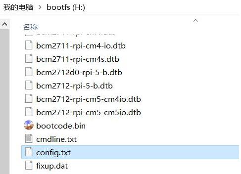
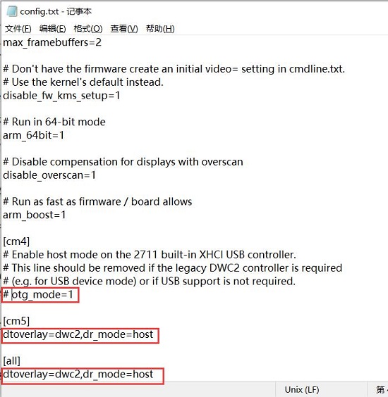
You need to confirm that the three red-boxed areas in the following image are all configured completely. If not, please manually add the missing parts and save the file:
# otg_mode=1 (It is recommended to comment out as follow)
dtoverlay=dwc2,dr_mode=host (These two areas must be ensured to be included.)
3.1.2 View network devices
The 4G module is automatically recognized in the Raspberry Pi OS, requires no drivers, and is plug-and-play.
Open the terminal in Raspberry Pi OS and enter the command ifconfig -a, as shown in the image below:
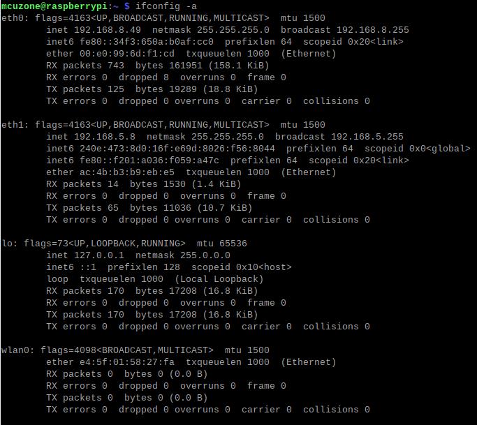
We can see that eth0 is a USB-to-Ethernet, and eth1 is a 4G Cat1 connection (with the IP address in the image above is 192.168.5.8).
3.2 Test network devices
3.2.1 ping tests
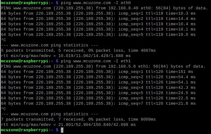
When testing, there is a priority order: if eth0 is connected, it will be used first. If there are specific requirements for internal and external networks, please adjust the metric values of each network and the DNS server settings.
Use the -I parameter to specify which network interface to start the ping packet from, as shown below:
ping www.mcuzone.com -I eth0
ping www.mcuzone.com -I eth1
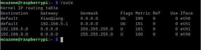
Priority can be checked by executing the route command; the network card with the smaller metric value will be preferred for communication.
We can also force communication through another network by disabling a specific network card. For example, to disable eth0, you can execute the following command:
sudo ifconfig eth0 down
And enable eth0 by the following command:
sudo ifconfig eth0 up
3.2.2 Set network adapter priority
To set the priority of network cards, you need to modify the metric value of the network card. First, we need to install the ifmetric software.
sudo apt install ifmetric

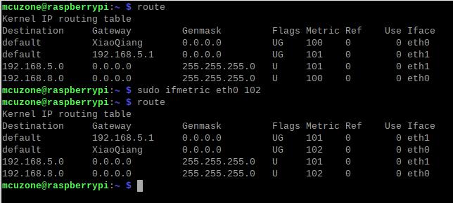
After the installation is complete, you can modify the metric value of the network card. If you need to change the metric value of eth0 to 102, you can execute:
sudo ifmetric eth0 102
After making the changes, use the route command to check, and we can see that the metric value of eth0 has been updated to 102:
However, this modification is only temporary; if the system is restarted, it will revert to its original state. To permanently change the metric value of eth0 to 102, you need to edit the startup file to achieve this.
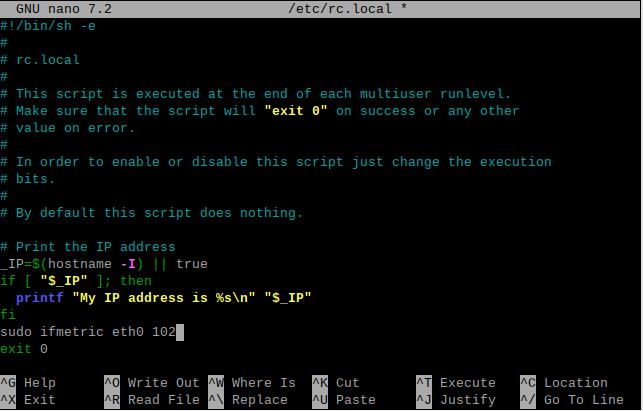
Open rc.local by the following command:
sudo nano /etc/rc.local
Add the command you want to execute at startup above exit 0, such as sudo ifmetric eth0 102, then save the file. You can modify the metric of eth0 every time the system starts by this way.

After modifying the metric values, it is possible that the system's nameserver (i.e., DNS server) is still using the previous higher-priority network card's nameserver. Since the default network card has now changed, this can lead to domain name resolution issues. So we also need to update the nameserver.
Open resolv.conf by the following command:
sudo nano /etc/resolv.conf

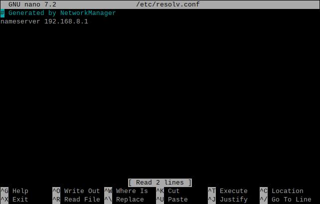
Check if the current nameserver is correct. If it is not, please change it to the nameserver of the network card with higher priority or to some common nameserver addresses (such as 8.8.8.8, etc.).
3.2.3 Using udhcpc to specify DNS servers
In the previous section, we discussed specifying DNS servers by modifying the nameserver. In fact, we can also achieve this by using udhcpc.
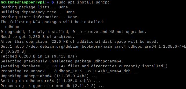
Install the udhcpc software:
sudo apt install udhcpc
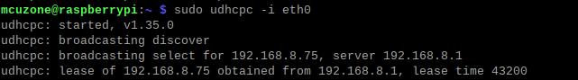
In this section, in the example we are testing, eth0 is a USB-to-Ethernet adapter, and usb0 is a 4G Cat1 (which corresponds to eth1 in the previous section). If we need to use the network DNS of the USB-to-Ethernet adapter (eth0), please use the following command:
sudo udhcpc -i eth0
If we need to use the network DNS of the 4G Cat1 (usb0), please use the following command:
sudo udhcpc -i usb0

3.2.4 Examples of how to use udhcpc
Example 1: The 100Mbps Ethernet port is connected to the Internet, and the 4G Cat1 is connected normally. In this case, if we ping a certain domain name, it will succeed:
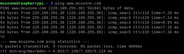
At this point, unplugging the 100M network port cable will make the ping fail:

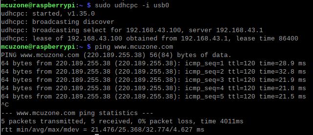
Run sudo udhcpc -i usb0 and switch the DNS server to 4G Cat1, then you should be able to ping normally:
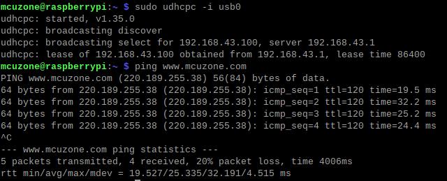
Example 2: The 100Mbps Ethernet port is connected to the internal network (not connected to the Internet), 4G Cat1 is connected normally. In this case, if we ping a certain domain name, it will failed:

Execute sudo udhcpc -i usb0, switch the DNS server to the 4G Cat1, and then you should be able to ping normally, and access internal network devices via the IP addresses:
3.2.5 Test speed by iperf3
You can download iperf3 (Windows version) in:
http://www.mcuzone.com/down/Software.asp?ID=10000634
Install iperf3 (Linux version) by using the following command:
sudo apt-get install iperf3
100M Ethernet speed test results: It is about 70Mbps in client mode and it is about 90Mbps in server mode:
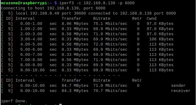
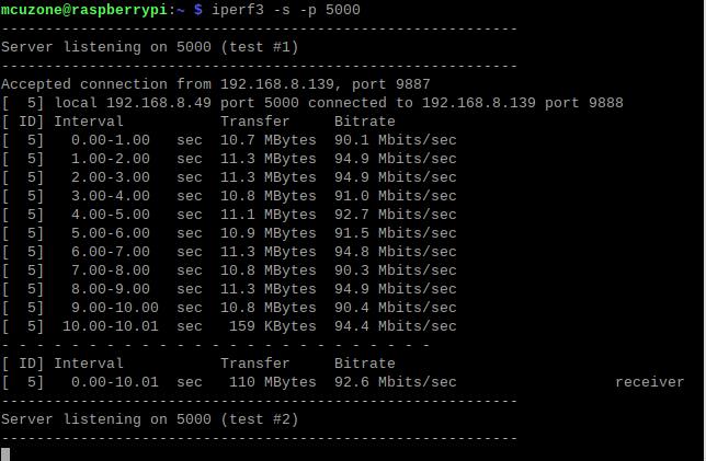
Note: The USB to 100M Ethernet adapter may not reach full speed due to the performance limitations of the Zero 2W, the USB hub, and the bandwidth usage of the 4G Cat1.
4G CAT1 speed test results:
Note: Network speed tests are affected by network conditions and testing methods. The actual speed may vary; this test is for reference only.
3.3 AT Command for 4G Cat1 Module
3.3.1 Open AT Command serial port
To operate 4G Cat1 Module using AT commands on a Raspberry Pi, you first need to open the AT command serial port. The method to open it is as follows:
Input the following command: lsusb, to open ttyUSB serial port:
If you use RPi0_RS485CAT1:
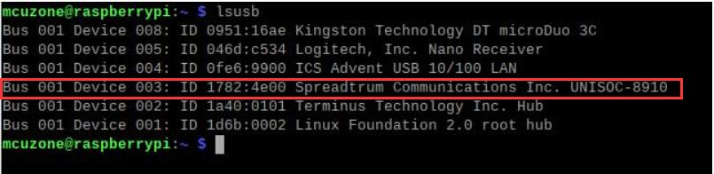
Record the ID value of the 4G module: 1782 4e00
Use the following command to open the ttyUSB serial port, where the value after echo is the ID recorded above:
sudo modprobe option
sudo sh -c 'echo 1782 4e00 > /sys/bus/usb-serial/drivers/option1/new_id'

If you use RPi0_RS485CAT1EU, RPi0_CAT1-ETH, RPi0_CAT1-EU_ETH:
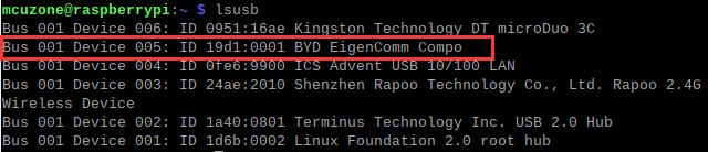
Record the ID value of the 4G module: 19d1 0001
Use the following command to open the ttyUSB serial port, where the value after echo is the ID recorded above:
sudo modprobe option
sudo sh -c 'echo 19d1 0001 > /sys/bus/usb-serial/drivers/option1/new_id'

After execution is complete, the system should have three additional devices: ttyUSB0, ttyUSB1, and ttyUSB2.
Then Open serial port by serial port tool.
Install minicom:
sudo apt-get install minicom

Open AT Command serial port by minicom:
sudo minicom -D /dev/ttyUSB0
Or
sudo minicom -D /dev/ttyUSB1

Then directly type the AT command and press Enter to see the result. If you need to view the echo, please type the command: ate1.
Note: The model of the 4G module may change, but the process remains the same. You only need to use lsusb to check the actual USB ID and replace it with the actual value in subsequent commands. Additionally, some 4G Cat1 modules's chipset IDs have already been included in the kernel's supported list, so these Cat1 modules can be automatically recognized as ttyAMAx without the need to add a USB ID.
3.3.2 Common AT commands
1) Check if the SIM card is detected:
at+cpin?
Return ready to indicate the card has been recognized, if return error, you need to check the hardware.
2) Check antenna signal quality:
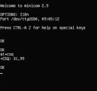
at+csq
Return values between 26 and 31 indicate a good signal, with 31 representing a full signal strength; return values between 20 and 25 indicate a barely acceptable signal; return values below 20 indicate a poor signal or that the antenna might not be connected.
3) Check network registration status:
at+cops?
Normally, it should return the network supporter's code: 7, where 7 represents 4G.
Note: The above command at+csq should not include a question mark, while the other two commands require a question mark.
4) View the SIM card's IMEI code:
at+cgsn
5) Reset 4G module (Sometimes, if you reinsert the SIM card, hot swapping may not work; in such cases, you can use this reset command to reset the module.):
at+reset
6) Disable radio frequency:
at+cfun=0
Enable radio frequency:
at+cfun=1
The two commands mentioned above can be used in pairs to allow the module to re-register with the network without restarting the 4G module.
3.4 RS485 serial test
If you are using the RS485 version, it has one fewer USB2.0-A host interface, which is replaced by an RS485 interface.
First, you need to install the serial port software CuteCom; the installation command is:
sudo apt install cutecom
After installation, click on the Raspberry Pi icon in the top left corner of the desktop, and under "System Tools," there will be a shortcut to CuteCom:
If there are permission issues during use, please open the Raspberry Pi OS terminal and enter:
sudo cutecom
to run the CuteCom.
This expansion board comes with a 4G module, which occupies three serial ports ttyUSB0-2. Therefore, the serial port number for the RS485 serial port is shifted to ttyUSB3.
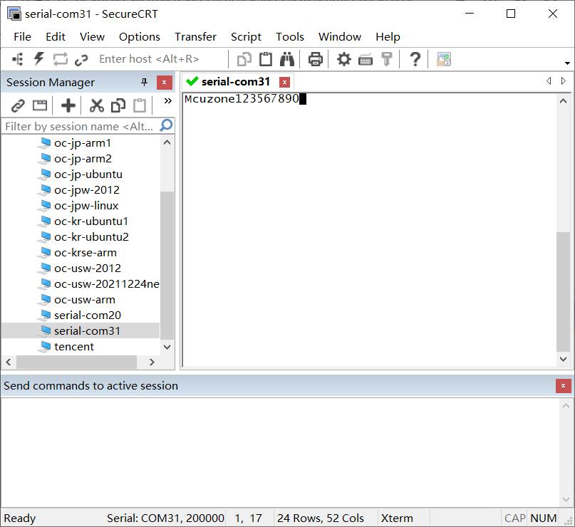
Plug a USB to RS485 converter into the PC and connect it to the RS485 port on the expansion board. Open the serial port software on each end for transmission and reception. The result is as follows:
Raspberry Pi OS:
Windows:
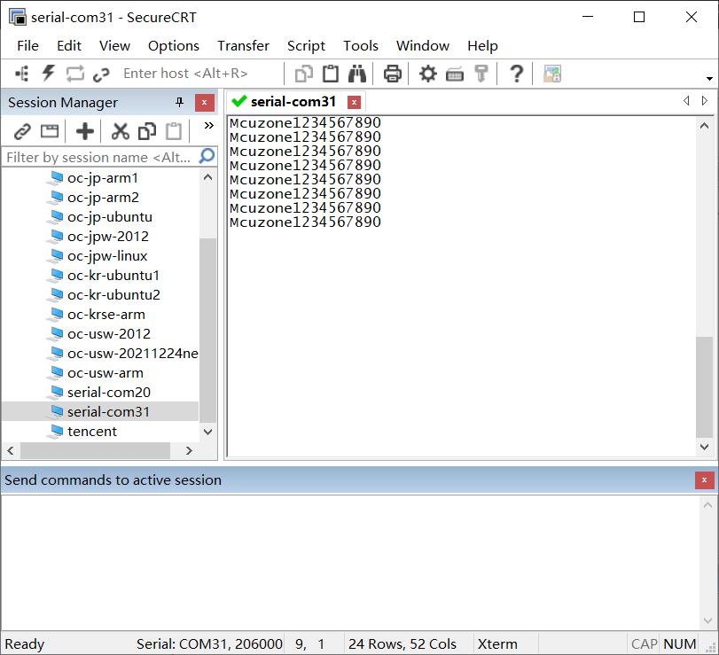
Through practical testing, the baud rate can reach up to 2.06M (based on the criterion that transmitted data does not become garbled).
IV. Work with Ubuntu OS
The hardware in this document is based on the Raspberry Pi Zero 2W.
Ubuntu system: Ubuntu Server 24.04 LTS. (The Raspberry Pi Zero 2W cannot use the Desktop version due to performance limitations.)
The image is: ubuntu-24.04-preinstalled-server-arm64+raspi.img.xz
You can download the Ubuntu system in:
https://ubuntu.com/download/raspberry-pi
4.1 Edit the initialization script
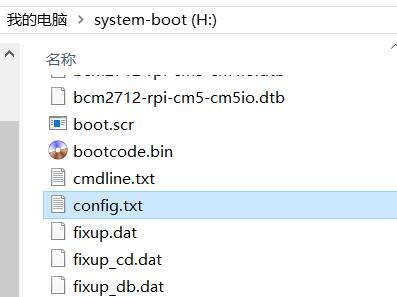
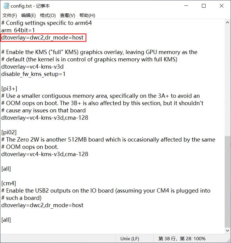
After flashing Ubuntu Server, please open the config.txt file located in the root directory of the system partition on the TF card on your PC to check the initialization script for USB. Ubuntu Server initializes the USB twice, but the first initialization does not configure it in host mode. Please verify that the area highlighted in red in the following image is configured properly. If it is not, please manually add the complete configuration:
dtoverlay=dwc2,dr_mode=host
4.2 Configure username and password
Insert the TF card into Zero 2W and boot up the system. Upon the first startup, you will be prompted to log in; both the username and password are "ubuntu." After logging in successfully, you will be asked to change the password.
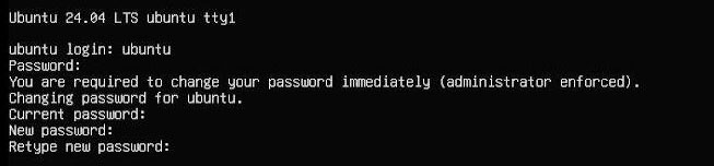
Once the password is changed, you will automatically enter the system.
4.3 Configure network
After system startup, there is no network available, and further configuration is needed before it can be used.
Note: the system does not integrate the ifconfig tool by default; only the ip command is available.
Execute ip addr to view and record the name of the network interface card:
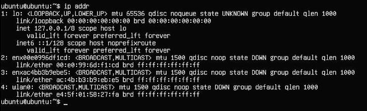
The second network interface card (enx00e0996df1cd) is a USB-to-100Mbps Ethernet adapter, and the third network interface card (enxac4bb3b9ebe5) is the 4G module.
Then run the following command to open the network interface card configuration file:
sudo nano /etc/netplan/50-cloud-init.yaml
Edit the network interface card configuration file according to the diagram below:
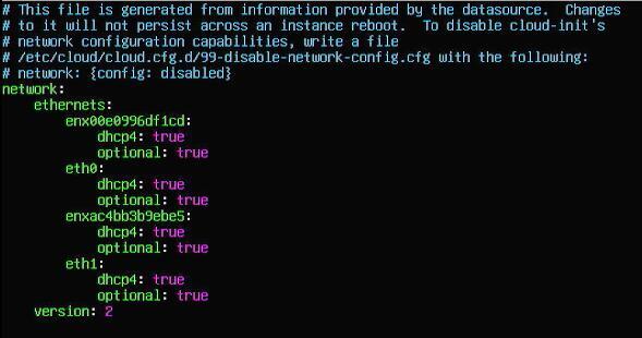
Save and exit, then reset the system.
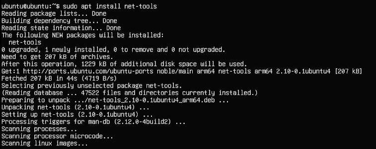
After rebooting, you can connect to the network. Install the net-tools to facilitate usage:
sudo apt install net-tools
4.4 Test network and 4G module
Run the command ifconfig -a to view the information of network:
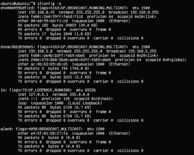
The first network interface card is a USB-to-100Mbps Ethernet adapter, and the second network interface card is the 4G module.
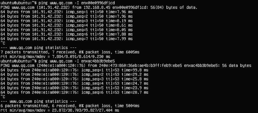
By using the -I parameter, you can specify the network interface name when sending ping packets, thus determining which interface to use for the ping. Through ping tests to Tencent's website using these two network interfaces, we can know that the second network interface (4G module) supports IPv6:
4.5 AT command interaction test
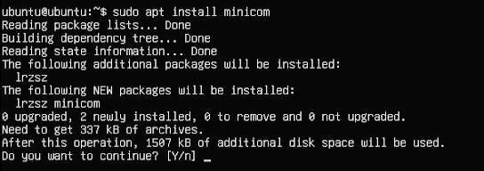
Install minicom:
sudo apt-get install minicom
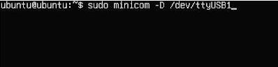
Open AT Command serial port by minicom:
sudo minicom -D /dev/ttyUSB0
Or
sudo minicom -D /dev/ttyUSB1
Now you can use common AT commands for interaction:
4.6 RS485 serial test
This expansion board comes with a 4G module, which occupies three serial ports ttyUSB0-2. Therefore, the serial port number for the RS485 serial port is shifted to ttyUSB3.
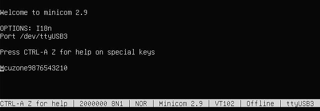
Plug a USB to RS485 converter into the PC and connect it to the RS485 port on the expansion board. Open the serial port software on each end for transmission and reception. We use minicom on Ubuntu system:
sudo minicom -D /dev/ttyUSB3
Through practical testing, the baud rate can reach up to 2.00M (based on the criterion that transmitted data does not become garbled).
Ubuntu system:
Windows:
V. Work with OpenWrt
5.1 Overview
This expansion board, when paired with the Raspberry Pi Zero 2W running OpenWrt, can be configured as a one-in-one-out switch mode. The 4G module on the expansion board can serve as the WAN port (for direct 4G internet access), while the Ethernet port is configured as the LAN port for connecting to a PC.
5.2 Preparation
The OpenWrt which be used in this document is: openwrt-bcm27xx-bcm2709-rpi-2-squashfs-sysupgrade-linux-6.1.98-20240723.img.gz
After flashing the OpenWrt system and powering it up, we connect an Ethernet cable from the Raspberry Pi's built-in Ethernet port to the PC's Ethernet port. Once the connection between the PC's network card and the Raspberry Pi's Ethernet port is successful, we find Network and Internet settings in Windows, then open the connected network under Ethernet to view the default gateway IP address. This address is the backend configuration page address for the OpenWrt system. As shown in the figure, the address for this test is 192.168.198.1:
Then open a web browser and enter 192.168.198.1 to access the OpenWrt system. The default username is root, and the default password is password.
5.3 Configure the OpenWrt system
After entering the OpenWrt system, connect the Raspberry Pi's Ethernet port directly to the PC's Ethernet port using an Ethernet cable. Once the PC's network card has acquired an IP address, the PC can directly access the internet through the 4G module (no additional settings required).
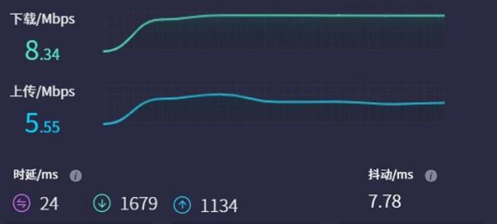
5.4 Test the network speed of 4G module
On the PC, open https://www.speedtest.cn/ to perform a speed test. At this point, the traffic goes through the 4G module, and the test results are as follows:
Note: The speed of 4G network testing is influenced by network signal strength and the testing method, so actual speeds may vary.
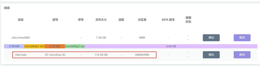
5.5 Mounting USB drive and file operations
When you insert a USB drive into a USB port, you can directly see the information and mounting status of the USB drive in "System - Disk Management":
In the "System - Mount Points" section, you can see the status of all mount points and can configure them on this page.
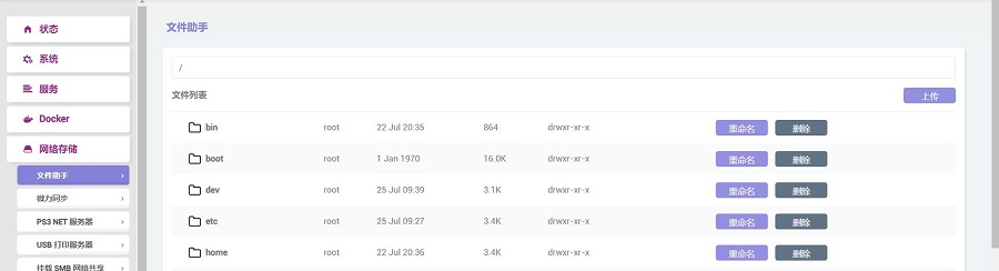
In the "Network Storage - File Assistant" section, you can perform operations on files within the system.
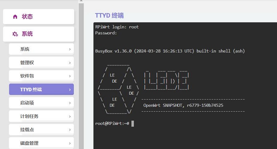
5.6 TTYD terminal
The OpenWrt system comes with a web-based TTYD terminal, which can be accessed in the "System - TTYD Terminal" section. The default username is root, and the default password is password. Since you log in with the root account, you will have root privileges upon logging in.
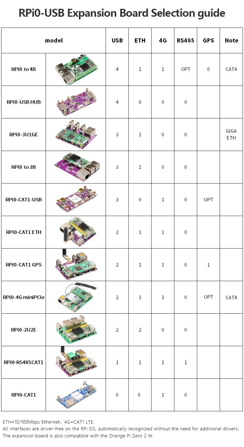
VI. Expansion board selection guide
Contact Us


 QQ:8204136
Email: mcuzone@vip.qq.com
Tel: +86(0)13957118045
If there are any omissions, errors, or infringements on this page, please contact us through the above methods. Thank you!
Copyright 2004-2025 Wildchip