1009 RPi0 DRS485 EN:修订间差异
无编辑摘要 |
|||
| (未显示同一用户的9个中间版本) | |||
| 第1行: | 第1行: | ||
[[1009 RPi0 DRS485|切换语言为中文]] | |||
== '''Keywords''' == | == '''Keywords''' == | ||
Raspberry Pi, Raspberry Pi Zero, Zero W, Zero WH, Zero 2W, USB2.0-A, Ethernet, Expansion Board, Dual RS485 | Raspberry Pi, Raspberry Pi Zero, Zero W, Zero WH, Zero 2W, USB2.0-A, Ethernet, Expansion Board, Dual RS485 | ||
| 第12行: | 第14行: | ||
1. 2*gold-plated pogo pins are used for power supply and USB communication on the expansion board, respectively. | 1. 2*gold-plated pogo pins are used for power supply and USB communication on the expansion board, respectively. | ||
2. 1*USB-C power supply interface is provided, which can be used to power the | 2. 1*USB-C power supply interface is provided, which can be used to power the OS (in this case, the Raspberry Pi Zero's Micro USB power port doesn't need additional power supply). Alternatively, you can use the Micro USB power port on the Zero for power supply (choose one power supply method). | ||
3. 1*100M Ethernet port. | 3. 1*100M Ethernet port. | ||
| 第18行: | 第20行: | ||
4. 1*USB 2.0 Type-A port. | 4. 1*USB 2.0 Type-A port. | ||
5. 1*RS485 module, industrial grade, with power isolation | 5. 1*RS485 module, industrial grade, with power isolation. | ||
6. | 6. Size: 69*55mm. | ||
7. | 7. The PCB material is UL and RoHS certified with a flammability rating of 94V-0. | ||
Note 1: The MicroUSB on the Zero will be unavailable after connecting this expansion board. | |||
Note 2: On some OSs, it is necessary to disable the OTG function and set the USB mode to Host mode. | |||
http://www.mcuzone.com/wiki/1009_RPi0_DRS485/1009_RPi0_DRS485_17.jpg | http://www.mcuzone.com/wiki/1009_RPi0_DRS485/1009_RPi0_DRS485_17.jpg | ||
| 第34行: | 第36行: | ||
http://www.mcuzone.com/wiki/1009_RPi0_DRS485/1009_RPi0_DRS485_19.jpg | http://www.mcuzone.com/wiki/1009_RPi0_DRS485/1009_RPi0_DRS485_19.jpg | ||
== ''' | == '''III. Work with Raspberry Pi OS''' == | ||
Hardware: Raspberry Pi Zero 2W, RPi0 DRS485 expansion board | |||
Software: The Raspberry Pi OS:(Raspberry Pi OS with desktop): 2024-07-04-raspios-bookworm-arm64.img.xz | |||
You can download the Raspberry Pi OS in: | |||
https://www.raspberrypi.com/software/operating-systems/#raspberry-pi-os-64-bit | https://www.raspberrypi.com/software/operating-systems/#raspberry-pi-os-64-bit | ||
(For Raspberry Pi Zero Gen 1 series, only 32-bit OS is supported. Please download the correct version.) | |||
=== 3.1 | === 3.1 View hardware devices === | ||
==== 3.1.1 | ==== 3.1.1 View USB devices ==== | ||
The USB-A port on the expansion board is connected to a wireless keyboard and mouse. Open the terminal, enter the command <code>lsusb</code>, as shown in the figure below: | |||
http://www.mcuzone.com/wiki/1009_RPi0_DRS485/1009_RPi0_DRS485_01.jpg | <html><img src="http://www.mcuzone.com/wiki/1009_RPi0_DRS485/1009_RPi0_DRS485_01.jpg" width=640></html> | ||
Device | Device 006: 100 Mbps Ethernet port. | ||
Device 005/ | Device 005/004: 2*USB to RS485 serial ports. | ||
Device | Device 003: USB 2.0-A port (for wireless keyboard/mouse). | ||
Device | Device 002: External USB Hub. | ||
''''' | '''''Note: If no device is connected to the USB port, the corresponding device ID will not appear in the <code>lsusb</code> output.''''' | ||
If the OS hangs on the Raspberry Pi logo and won't boot: | |||
http://www.mcuzone.com/wiki/0007_Zero_4G_Cat1/0007_Zero_4G_Cat1_58.jpg | http://www.mcuzone.com/wiki/0007_Zero_4G_Cat1/0007_Zero_4G_Cat1_58.jpg | ||
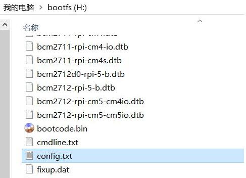
If the keyboard or mouse fails to work after startup, please carefully check whether the pogo pins are correctly positioned against the gold-plated contact points. Also, open the <code>config.txt</code> file in the root directory of the system partition on the TF card via a PC and verify the USB initialization script. | |||
http://www.mcuzone.com/wiki/0007_Zero_4G_Cat1/0007_Zero_4G_Cat1_41.jpg | <html><img src="http://www.mcuzone.com/wiki/0007_Zero_4G_Cat1/0007_Zero_4G_Cat1_41.jpg" style="border: 1px solid black;"></html> | ||
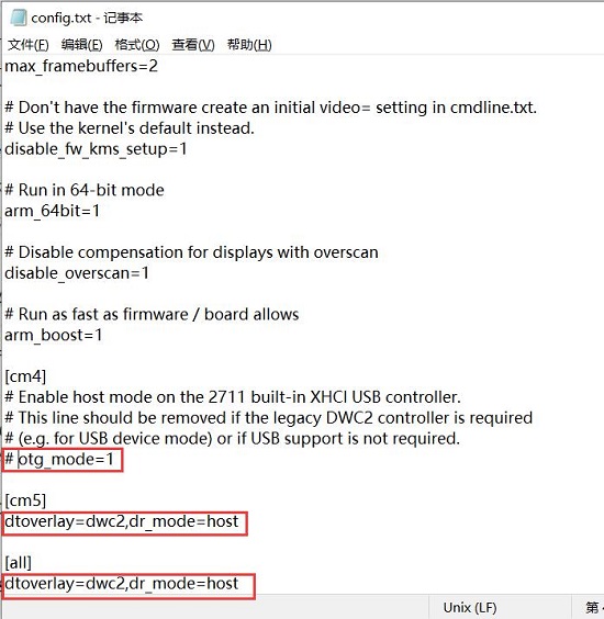
Please check if all three red-boxed areas in the image are fully configured. If not, manually complete them and save the file. | |||
<code># otg_mode=1</code> | <code># otg_mode=1</code> (Recommended to comment out) | ||
<code>dtoverlay=dwc2,dr_mode=host</code> | <code>dtoverlay=dwc2,dr_mode=host</code> (Must be added in both places) | ||
http://www.mcuzone.com/wiki/0007_Zero_4G_Cat1/0007_Zero_4G_Cat1_57.jpg | <html><img src="http://www.mcuzone.com/wiki/0007_Zero_4G_Cat1/0007_Zero_4G_Cat1_57.jpg" style="border: 1px solid black;"></html> | ||
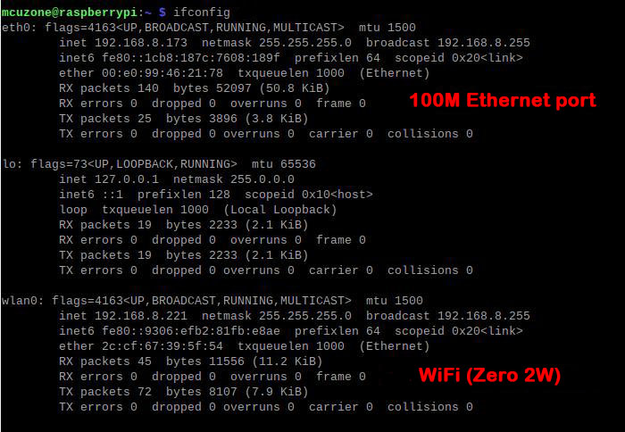
==== 3.1.2 | ==== 3.1.2 View network devices ==== | ||
Open the terminal, enter the command <code>ifconfig</code>, as shown in the following image: | |||
http://www.mcuzone.com/wiki/1009_RPi0_DRS485/ | <html><img src="http://www.mcuzone.com/wiki/1009_RPi0_DRS485/1009_RPi0_DRS485_23.jpg" width=640></html> | ||
=== 3.2 | === 3.2 Test network devices === | ||
==== 3.2.1 | ==== 3.2.1 ping tests ==== | ||
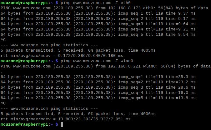
Use the -I parameter to specify which network interface to start the ping packet from, as shown below: | |||
<code>ping www.mcuzone.com -I eth0</code> | <code>ping www.mcuzone.com -I eth0</code> | ||
| 第90行: | 第94行: | ||
<code>ping www.mcuzone.com -I wlan0</code> | <code>ping www.mcuzone.com -I wlan0</code> | ||
http://www.mcuzone.com/wiki/1009_RPi0_DRS485/1009_RPi0_DRS485_03.jpg | <html><img src="http://www.mcuzone.com/wiki/1009_RPi0_DRS485/1009_RPi0_DRS485_03.jpg" width=640></html> | ||
We can also force communication through another network by disabling a specific network card. For example, to disable eth0, you can execute the following command: | |||
<code>sudo ifconfig eth0 down</code> | <code>sudo ifconfig eth0 down</code> | ||
And enable eth0 by the following command: | |||
<code>sudo ifconfig eth0 up</code> | <code>sudo ifconfig eth0 up</code> | ||
==== 3.2.3 | ==== 3.2.3 Test speed by iperf3 ==== | ||
You can download iperf3 (Windows version) in: | |||
http://www.mcuzone.com/down/Software.asp?ID=10000634 | http://www.mcuzone.com/down/Software.asp?ID=10000634 | ||
Install iperf3 (Linux version) by using the following command: | |||
<code>sudo apt-get install iperf3</code> | <code>sudo apt-get install iperf3</code> | ||
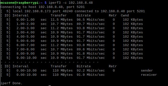
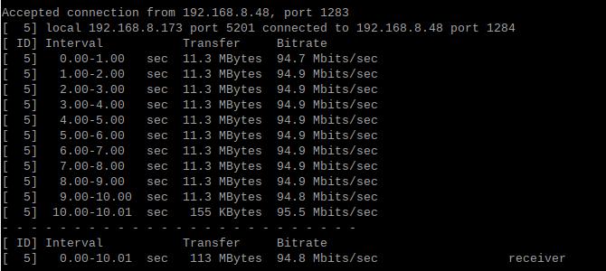
100M Ethernet speed test results: It is about 92Mbps in client mode and it is about 95Mbps in server mode: | |||
<html><img src="http://www.mcuzone.com/wiki/1009_RPi0_DRS485/1009_RPi0_DRS485_04.jpg" width=640></html> | |||
http://www.mcuzone.com/wiki/1009_RPi0_DRS485/1009_RPi0_DRS485_05.jpg | <html><img src="http://www.mcuzone.com/wiki/1009_RPi0_DRS485/1009_RPi0_DRS485_05.jpg" width=640></html> | ||
''''' | '''''Note: The speed of the USB to 100M Ethernet is limited by the performance of the Zero 2W and the bandwidth usage of the USB Hub. Actual speeds may vary. This speed test result is for reference only.''''' | ||
=== 3.3 | === 3.3 Dual RS485 Interface Test === | ||
For the test, the serial port software CuteCom needs to be installed. The installation command is: | |||
<code>sudo apt install cutecom</code> | <code>sudo apt install cutecom</code> | ||
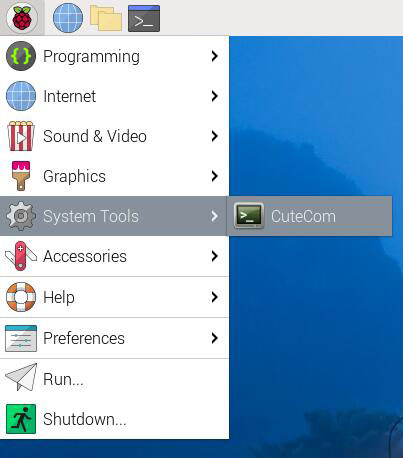
Once the installation is finished, click the Raspberry Pi icon at the top-left of the desktop, and the CuteCom shortcut can be found in "System Tools". | |||
http://www.mcuzone.com/wiki/0012_MPUUART_MP4232/0012_MPUUART_MP4232_01.jpg | http://www.mcuzone.com/wiki/0012_MPUUART_MP4232/0012_MPUUART_MP4232_01.jpg | ||
If you encounter insufficient permissions during use, please open the terminal and enter the following shortcut: | |||
<code>sudo cutecom</code> | <code>sudo cutecom</code> | ||
Please start CuteCom later. Two RS485 interfaces, as shown in the figure below. | |||
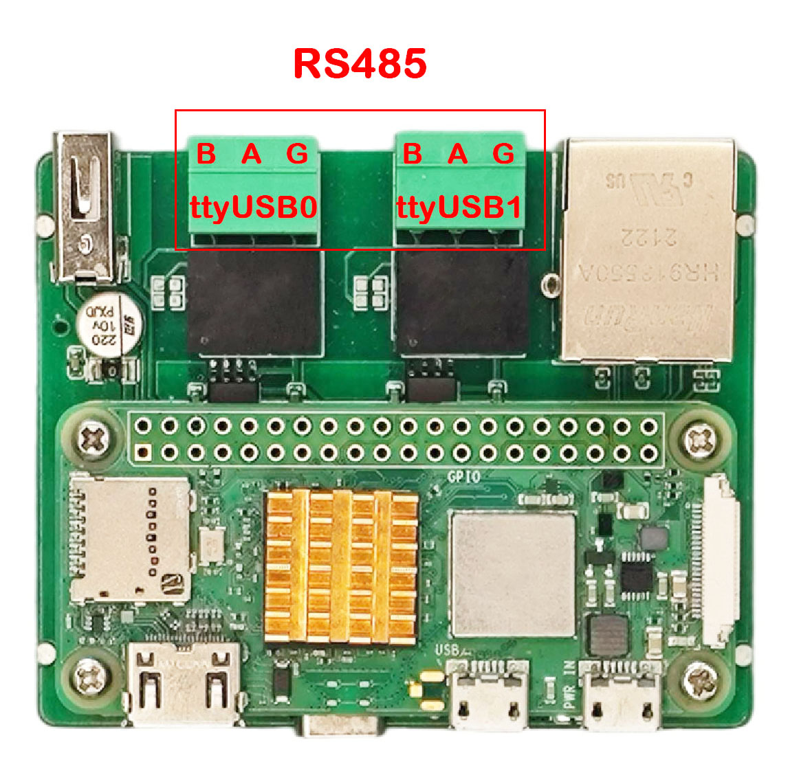
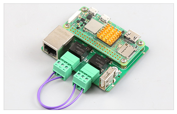
<html><img src="http://www.mcuzone.com/wiki/1009_RPi0_DRS485/1009_RPi0_DRS485_16.jpg" width=440></html> | <html><img src="http://www.mcuzone.com/wiki/1009_RPi0_DRS485/1009_RPi0_DRS485_16.jpg" width=440></html> | ||
==== 3.3.1 | ==== 3.3.1 Testing data transfer between RS485 and PC ==== | ||
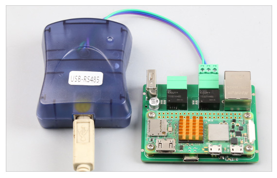
http://www.mcuzone.com/wiki/1009_RPi0_DRS485/1009_RPi0_DRS485_21.jpg | http://www.mcuzone.com/wiki/1009_RPi0_DRS485/1009_RPi0_DRS485_21.jpg | ||
''' | '''Testing data transfer between ttyUSB0 and the PC:''' | ||
On the PC side, plug in a USB-to-485 converter and connect it to the RS485 interface (ttyUSB0) on the expansion board. Then, open serial port software on both sides for sending and receiving data. The results are as follows: | |||
Raspberry Pi OS/Windows: | |||
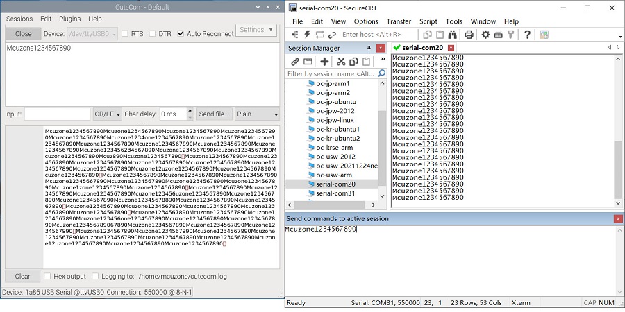
http://www.mcuzone.com/wiki/1009_RPi0_DRS485/1009_RPi0_DRS485_07.jpg | http://www.mcuzone.com/wiki/1009_RPi0_DRS485/1009_RPi0_DRS485_07.jpg | ||
Through actual testing, the maximum baud rate can reach 550kbps (based on the condition that no data corruption or loss occurs during transmission). | |||
''' | '''Testing data transfer between ttyUSB1 and the PC:''' | ||
On the PC side, plug in a USB-to-485 converter and connect it to the RS485 interface (ttyUSB1) on the expansion board. Then, open serial port software on both sides for sending and receiving data. The results are as follows: | |||
Raspberry Pi OS/Windows: | |||
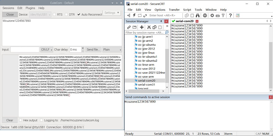
http://www.mcuzone.com/wiki/1009_RPi0_DRS485/1009_RPi0_DRS485_08.jpg | http://www.mcuzone.com/wiki/1009_RPi0_DRS485/1009_RPi0_DRS485_08.jpg | ||
Through actual testing, the maximum baud rate can reach 600kbps (based on the condition that no data corruption or loss occurs during transmission). | |||
==== 3.2.2 | ==== 3.2.2 Testing data transfer between two RS485 ports ==== | ||
http://www.mcuzone.com/wiki/1009_RPi0_DRS485/1009_RPi0_DRS485_20.jpg | http://www.mcuzone.com/wiki/1009_RPi0_DRS485/1009_RPi0_DRS485_20.jpg | ||
Connect the two RS485 ports (ttyUSB0 and ttyUSB1) on the expansion board, open serial port software on each for sending and receiving, with the following results: | |||
Raspberry Pi OS(ttyUSB0)/Raspberry Pi OS(ttyUSB1): | |||
http://www.mcuzone.com/wiki/1009_RPi0_DRS485/1009_RPi0_DRS485_09.jpg | http://www.mcuzone.com/wiki/1009_RPi0_DRS485/1009_RPi0_DRS485_09.jpg | ||
Through actual testing, the maximum baud rate can reach 2.5Mbps (based on the condition that no data corruption or loss occurs during transmission). | |||
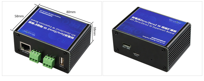
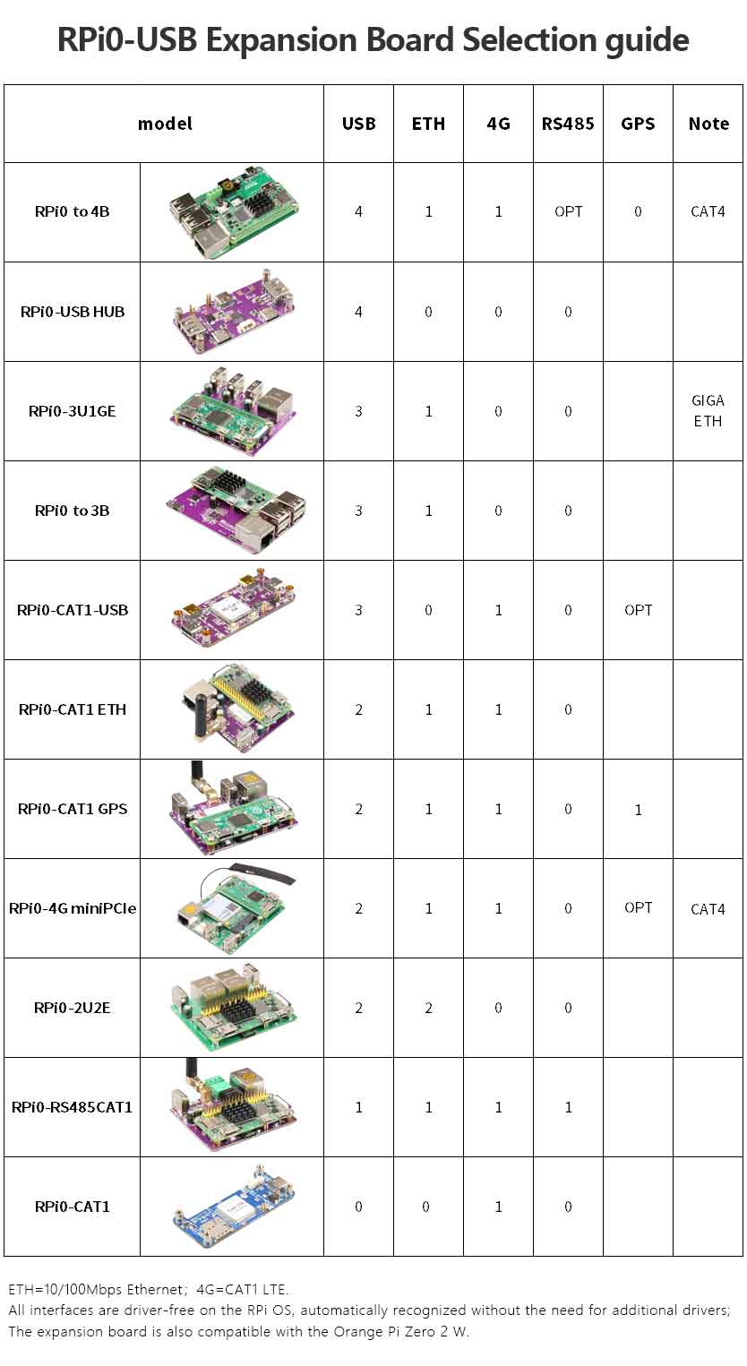
== '''IV. Expansion board selection guide''' == | |||
http://www.mcuzone.com/wiki/1006_RPi0_4G_MiniPCIe/1006_RPi0_4G_MiniPCIe_65.jpg | |||
{{Contact_Us_icon}} | |||
2025年4月14日 (一) 16:02的最新版本
Keywords
Raspberry Pi, Raspberry Pi Zero, Zero W, Zero WH, Zero 2W, USB2.0-A, Ethernet, Expansion Board, Dual RS485
I. Introduction
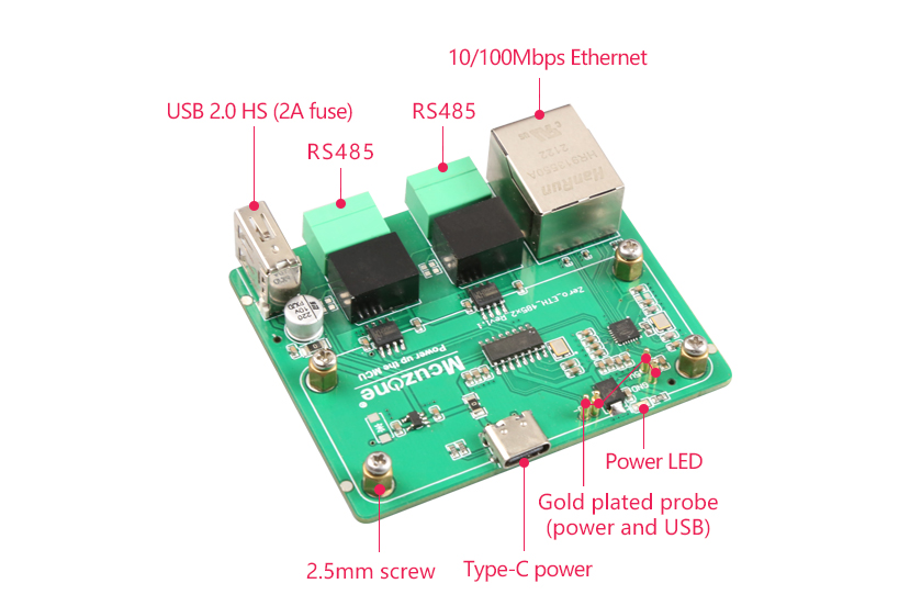
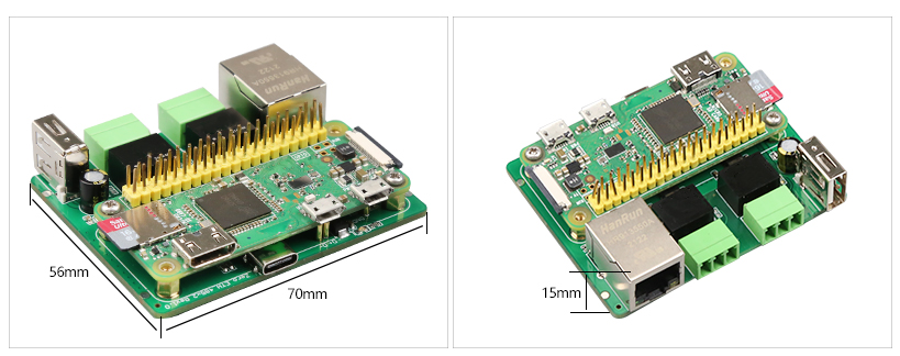
This expansion board is based on the Raspberry Pi Zero series development board. Utilizing the USB and power contacts on the reverse side of the Zero, it connects to the Zero via gold-plated pogo pins, expanding two RS485 interfaces, one 100M Ethernet port, and one USB 2.0 port. The expansion board acts as a USB hub, using the Zero's native USB port as a host. Thus, the Raspberry Pi Zero's built-in USB port cannot support additional external devices. The entire system is powered via USB-C, requiring no additional power for the Raspberry Pi Zero, and without occupying the 40-pin GPIO port of the Zero.
The expansion board supports the full range of Raspberry Pi Zero series development boards, including the Zero, Zero W, Zero WH, and Zero 2W.
The RS845 module is industrial-grade with power isolation, supporting speeds up to 600Kbps and 64 nodes.
II. Hardware Spec
1. 2*gold-plated pogo pins are used for power supply and USB communication on the expansion board, respectively.
2. 1*USB-C power supply interface is provided, which can be used to power the OS (in this case, the Raspberry Pi Zero's Micro USB power port doesn't need additional power supply). Alternatively, you can use the Micro USB power port on the Zero for power supply (choose one power supply method).
3. 1*100M Ethernet port.
4. 1*USB 2.0 Type-A port.
5. 1*RS485 module, industrial grade, with power isolation.
6. Size: 69*55mm.
7. The PCB material is UL and RoHS certified with a flammability rating of 94V-0.
Note 1: The MicroUSB on the Zero will be unavailable after connecting this expansion board.
Note 2: On some OSs, it is necessary to disable the OTG function and set the USB mode to Host mode.
III. Work with Raspberry Pi OS
Hardware: Raspberry Pi Zero 2W, RPi0 DRS485 expansion board
Software: The Raspberry Pi OS:(Raspberry Pi OS with desktop): 2024-07-04-raspios-bookworm-arm64.img.xz
You can download the Raspberry Pi OS in:
https://www.raspberrypi.com/software/operating-systems/#raspberry-pi-os-64-bit
(For Raspberry Pi Zero Gen 1 series, only 32-bit OS is supported. Please download the correct version.)
3.1 View hardware devices
3.1.1 View USB devices
The USB-A port on the expansion board is connected to a wireless keyboard and mouse. Open the terminal, enter the command lsusb, as shown in the figure below:
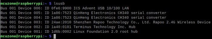
Device 006: 100 Mbps Ethernet port.
Device 005/004: 2*USB to RS485 serial ports.
Device 003: USB 2.0-A port (for wireless keyboard/mouse).
Device 002: External USB Hub.
Note: If no device is connected to the USB port, the corresponding device ID will not appear in the lsusb output.
If the OS hangs on the Raspberry Pi logo and won't boot:
If the keyboard or mouse fails to work after startup, please carefully check whether the pogo pins are correctly positioned against the gold-plated contact points. Also, open the config.txt file in the root directory of the system partition on the TF card via a PC and verify the USB initialization script.
Please check if all three red-boxed areas in the image are fully configured. If not, manually complete them and save the file.
# otg_mode=1 (Recommended to comment out)
dtoverlay=dwc2,dr_mode=host (Must be added in both places)
3.1.2 View network devices
Open the terminal, enter the command ifconfig, as shown in the following image:
3.2 Test network devices
3.2.1 ping tests
Use the -I parameter to specify which network interface to start the ping packet from, as shown below:
ping www.mcuzone.com -I eth0
ping www.mcuzone.com -I wlan0
We can also force communication through another network by disabling a specific network card. For example, to disable eth0, you can execute the following command:
sudo ifconfig eth0 down
And enable eth0 by the following command:
sudo ifconfig eth0 up
3.2.3 Test speed by iperf3
You can download iperf3 (Windows version) in:
http://www.mcuzone.com/down/Software.asp?ID=10000634
Install iperf3 (Linux version) by using the following command:
sudo apt-get install iperf3
100M Ethernet speed test results: It is about 92Mbps in client mode and it is about 95Mbps in server mode:
Note: The speed of the USB to 100M Ethernet is limited by the performance of the Zero 2W and the bandwidth usage of the USB Hub. Actual speeds may vary. This speed test result is for reference only.
3.3 Dual RS485 Interface Test
For the test, the serial port software CuteCom needs to be installed. The installation command is:
sudo apt install cutecom
Once the installation is finished, click the Raspberry Pi icon at the top-left of the desktop, and the CuteCom shortcut can be found in "System Tools".
If you encounter insufficient permissions during use, please open the terminal and enter the following shortcut:
sudo cutecom
Please start CuteCom later. Two RS485 interfaces, as shown in the figure below.
3.3.1 Testing data transfer between RS485 and PC
Testing data transfer between ttyUSB0 and the PC:
On the PC side, plug in a USB-to-485 converter and connect it to the RS485 interface (ttyUSB0) on the expansion board. Then, open serial port software on both sides for sending and receiving data. The results are as follows:
Raspberry Pi OS/Windows:
Through actual testing, the maximum baud rate can reach 550kbps (based on the condition that no data corruption or loss occurs during transmission).
Testing data transfer between ttyUSB1 and the PC:
On the PC side, plug in a USB-to-485 converter and connect it to the RS485 interface (ttyUSB1) on the expansion board. Then, open serial port software on both sides for sending and receiving data. The results are as follows:
Raspberry Pi OS/Windows:
Through actual testing, the maximum baud rate can reach 600kbps (based on the condition that no data corruption or loss occurs during transmission).
3.2.2 Testing data transfer between two RS485 ports
Connect the two RS485 ports (ttyUSB0 and ttyUSB1) on the expansion board, open serial port software on each for sending and receiving, with the following results:
Raspberry Pi OS(ttyUSB0)/Raspberry Pi OS(ttyUSB1):
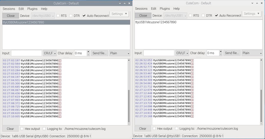
Through actual testing, the maximum baud rate can reach 2.5Mbps (based on the condition that no data corruption or loss occurs during transmission).
IV. Expansion board selection guide
Contact Us


 QQ:8204136
Email: mcuzone@vip.qq.com
Tel: +86(0)13957118045
If there are any omissions, errors, or infringements on this page, please contact us through the above methods. Thank you!
Copyright 2004-2025 Wildchip