0001 MPRG4(Designed based on Raspberry Pi 5 PCIe):修订间差异
无编辑摘要 |
|||
| (未显示同一用户的6个中间版本) | |||
| 第1行: | 第1行: | ||
[[MPRG4(基于树莓派5 PCIE设计)|切换语言为中文]] | [[MPRG4(基于树莓派5 PCIE设计)|切换语言为中文]] | ||
== | =='''Keywords'''== | ||
Raspberry Pi 5 MPRG4 Quad-Gigabit Ethernet Expansion Board Pi OS Ubuntu OpenWrt software router switch | Raspberry Pi 5 MPRG4 Quad-Gigabit Ethernet Expansion Board Pi OS Ubuntu OpenWrt software router switch | ||
== | =='''I. Introduction'''== | ||
The MPRG4 (also known as MPG4) is a Quad-Gigabit Ethernet expansion board designed specifically for the Raspberry Pi 5, utilizing the PCIe interface. This expansion board connects the RTL8111H PCIe Ethernet controller via the PCIe interface, and then extends into four Gigabit Ethernet ports through a switch chip. It can be used in the following scenarios: | The MPRG4 (also known as MPG4) is a Quad-Gigabit Ethernet expansion board designed specifically for the Raspberry Pi 5, utilizing the PCIe interface. This expansion board connects the RTL8111H PCIe Ethernet controller via the PCIe interface, and then extends into four Gigabit Ethernet ports through a switch chip. It can be used in the following scenarios: | ||
| 第13行: | 第13行: | ||
Note2: In the Raspberry Pi or Ubuntu system, if the network cable is not plugged in at startup, the system will obtain an IP address like 169.254.xx.xx after a while. At this time, even if you plug in a network cable from an upstream router, the system will not obtain a valid IP address. You need to press the reset button on the expansion board's switch to acquire a valid IP address again. | Note2: In the Raspberry Pi or Ubuntu system, if the network cable is not plugged in at startup, the system will obtain an IP address like 169.254.xx.xx after a while. At this time, even if you plug in a network cable from an upstream router, the system will not obtain a valid IP address. You need to press the reset button on the expansion board's switch to acquire a valid IP address again. | ||
== | =='''II. Hardware Resources'''== | ||
1. It connected via a 16-pin 0.5mm FPC to Raspberry Pi 5. | 1. It connected via a 16-pin 0.5mm FPC to Raspberry Pi 5. | ||
| 第32行: | 第32行: | ||
9. Board size: about 86mm*75mm. | 9. Board size: about 86mm*75mm. | ||
http://www.mcuzone.com/wiki/0001_MPRG4/MPRG4_35.jpg | |||
http://www.mcuzone.com/wiki/0001_MPRG4/ | http://www.mcuzone.com/wiki/0001_MPRG4/MPRG4_36.jpg | ||
http://www.mcuzone.com/wiki/0001_MPRG4/ | http://www.mcuzone.com/wiki/0001_MPRG4/MPRG4_37.jpg | ||
http://www.mcuzone.com/wiki/0001_MPRG4/ | http://www.mcuzone.com/wiki/0001_MPRG4/MPRG4_38.jpg | ||
A 4G module can be installed on top of the Raspberry Pi 5 to set up a 4G router. The 4G module is an optional module. | |||
Note: Four network ports cannot be used to connect to upstream routing devices in different network segments, it can not achieve such as multi-carrier aggregation with connections both from China Telecom and China Unicom. It also can not achieve to prevents bridge applications with one port connects to the Internet and another to an internal network. | |||
== '''III. Work with Raspberry Pi OS''' == | |||
Under the Raspberry Pi system, the necessary drivers are integrated by default, so no additional driver installation is required, and you can use it directly. | |||
You can download the Raspberry Pi OS in: | |||
https://www.raspberrypi.com/software/operating-systems/ | |||
=== 3.1 System flashing === | |||
Please flash the Raspberry Pi system as needed, supporting both 32-bit and 64-bit systems. Since the PCIe interface is occupied, it can be booted from a TF card. | |||
2 | [[0005 MPS2242 2280 2280P(Single SSD Expansion Board)#3.2 Boot from TF card|Click here to read the instructions for System flashing]] | ||
3. After the system starts, execute <code>ifconfig -a</code>, and you will see an <code>eth1</code> device, which is the extended RTL8111H network card. | === 3.2 View network === | ||
After the system starts, execute <code>ifconfig -a</code>, and you will see an <code>eth1</code> device, which is the extended RTL8111H network card. | |||
http://www.mcuzone.com/wiki/0001_MPRG4/ | http://www.mcuzone.com/wiki/0001_MPRG4/MPRG4_32.jpg | ||
=== 3.3 Test network === | |||
Connect the PC to any of the four network ports. Run iperf3 on both the Raspberry Pi and the PC to measure the speed. It can run the full speed. | |||
Download iperf3(Windows version): | Download iperf3(Windows version): | ||
| 第63行: | 第70行: | ||
Install iperf3 on Linux: | Install iperf3 on Linux: | ||
sudo apt-get install iperf3 | |||
http://www.mcuzone.com/wiki/0001_MPRG4/MPRG4_03.jpg | http://www.mcuzone.com/wiki/0001_MPRG4/MPRG4_03.jpg | ||
The iperf3 test between the four network ports can also run at full speed. | The iperf3 test between the four network ports can also run at full speed. | ||
| 第75行: | 第79行: | ||
Note2:If there is no network cable plugged into the upstream router before booting up, even if you plug the cable later, you won't be able to access the network (IP address will be obtained an IP address as 169.254.xx.xx). You need to press the reset button on the switch (marked as Switch RST). | Note2:If there is no network cable plugged into the upstream router before booting up, even if you plug the cable later, you won't be able to access the network (IP address will be obtained an IP address as 169.254.xx.xx). You need to press the reset button on the switch (marked as Switch RST). | ||
== '''IV. Work with Ubuntu System''' == | |||
== | The process of loading network card drivers in Ubuntu 23.10 is relatively complex and cumbersome, and it is not recommended for use. | ||
The version of the Ubuntu system is: ubuntu-24.04-preinstalled-desktop-arm64+raspi.img.xz | |||
You can download the Ubuntu system in: | |||
https://ubuntu.com/download/raspberry-pi | |||
===4.1 Install drivers=== | |||
=== | |||
On Ubuntu 24.04, you can directly download driver source code and compile it. The steps are as follows: | On Ubuntu 24.04, you can directly download driver source code and compile it. The steps are as follows: | ||
| 第157行: | 第102行: | ||
<code>sudo modprobe r8168</code> | <code>sudo modprobe r8168</code> | ||
=== 4.2 Test network === | |||
Run the following command to view the wired network interface which is named enxxx: | Run the following command to view the wired network interface which is named enxxx: | ||
<code>ifconfig -a</code> | <code>ifconfig -a</code> | ||
http://www.mcuzone.com/wiki/0001_MPRG4/MPRG4_05. | http://www.mcuzone.com/wiki/0001_MPRG4/MPRG4_05.pngUsing iperf3 for speed testing, it can be run on gigabit speed. | ||
http://www.mcuzone.com/wiki/0001_MPRG4/MPRG4_06.png | http://www.mcuzone.com/wiki/0001_MPRG4/MPRG4_06.png | ||
| 第171行: | 第113行: | ||
'''''Note: On an Ubuntu system, the RTL8111H network card is recognized with a name like enxxxx, while the same switch used as a physical layer chip does not appear in the network card list.''''' | '''''Note: On an Ubuntu system, the RTL8111H network card is recognized with a name like enxxxx, while the same switch used as a physical layer chip does not appear in the network card list.''''' | ||
== ''' | == '''V. Work with OpenWrt System''' == | ||
=== | === 5.1 Overview === | ||
The MPRG4 expansion board can be configured in OpenWrt system as a switch with one input and four outputs. | The MPRG4 expansion board can be configured in OpenWrt system as a switch with one input and four outputs. We can configure the Raspberry Pi's built-in Ethernet port as the WAN port, and use the four Ethernet ports on the expansion board as LAN ports, which can be used by other devices to obtain IP addresses within the same subnet. | ||
System version: openwrt-bcm27xx-bcm2712-rpi-5-squashfs-sysupgrade-linux-6.1.92-20240530a.img.gz | System version: openwrt-bcm27xx-bcm2712-rpi-5-squashfs-sysupgrade-linux-6.1.92-20240530a.img.gz | ||
=== 5.2 Preparation === | |||
By default, the Raspberry Pi's built-in Ethernet port is configured as a LAN port. We can connect an Ethernet cable from the Raspberry Pi's built-in Ethernet port to the PC's Ethernet port. After powering on and booting the system, open a web browser and enter 192.168.198.1 to access the OpenWrt system. | |||
Default username is<code>root</code>, Default password is<code>password</code>. | Default username is<code>root</code>, Default password is<code>password</code>. | ||
| 第189行: | 第131行: | ||
http://www.mcuzone.com/wiki/0001_MPRG4/MPRG4_18.png | http://www.mcuzone.com/wiki/0001_MPRG4/MPRG4_18.png | ||
On the computer, use a terminal software (such as SecureCRT) to connect to the development board, and you will see that the network devices have been successfully recognized. By default, eth0 is configured as the LAN port, which is the Raspberry Pi's built-in Ethernet port. Here, it is set to bridge mode, and the network address can be found in br-lan. | |||
http://www.mcuzone.com/wiki/0001_MPRG4/MPRG4_21.png | http://www.mcuzone.com/wiki/0001_MPRG4/MPRG4_21.png | ||
| 第201行: | 第143行: | ||
http://www.mcuzone.com/wiki/0001_MPRG4/MPRG4_20.png | http://www.mcuzone.com/wiki/0001_MPRG4/MPRG4_20.png | ||
=== Configure the OpenWrt system | === 5.3 Configure the OpenWrt system === | ||
After the device is properly recognized, we open the "network - interface". | After the device is properly recognized, we open the "network - interface". | ||
| 第224行: | 第166行: | ||
http://www.mcuzone.com/wiki/0001_MPRG4/MPRG4_27.png | http://www.mcuzone.com/wiki/0001_MPRG4/MPRG4_27.png | ||
After setting up, we click "Save & Apply". Please note that since the network settings are being changed, it will continuously display "Applying changes". This is not a malfunction, and after waiting for a while, we can proceed to the next step. | After setting up, we click "Save & Apply". Please note that since the network settings are being changed, it will continuously display "Applying changes". This is not a malfunction, and after waiting for a while, we can proceed to the next step.http://www.mcuzone.com/wiki/0001_MPRG4/MPRG4_28.png | ||
http://www.mcuzone.com/wiki/0001_MPRG4/MPRG4_28.png | |||
=== Network test | === 5.4 Network test === | ||
Restart the device and connect the new WAN port, which is the Raspberry Pi's built-in Ethernet port, to the upstream router. The four Ethernet ports on the expansion board will now act as LAN ports and can be used to connect other network devices to obtain network access. We'll connect two of the LAN ports to two PCs to simply test the network bandwidth. | |||
Using iperf3 to test between two computers shows that the test results are normal. | Using iperf3 to test between two computers shows that the test results are normal. | ||
| 第237行: | 第177行: | ||
http://www.mcuzone.com/wiki/0001_MPRG4/MPRG4_30.png | http://www.mcuzone.com/wiki/0001_MPRG4/MPRG4_30.png | ||
== ''' | == '''VI. Radxa Rock 5C (RK3588S2) with MPRG4 expansion board''' == | ||
=== | === 6.1 Overview === | ||
The Radxa Rock 5C is designed based on the RK3588S2, it have one gigabit ethernet port and four USB ports, along with a PCIe interface compatible with the Raspberry Pi 5. This interface allows us to expand with various PCIe extension boards originally designed for the Raspberry Pi 5. In this demonstration, we are using a four-network-port expansion board. | The Radxa Rock 5C is designed based on the RK3588S2, it have one gigabit ethernet port and four USB ports, along with a PCIe interface compatible with the Raspberry Pi 5. This interface allows us to expand with various PCIe extension boards originally designed for the Raspberry Pi 5. In this demonstration, we are using a four-network-port expansion board. | ||
=== The software and hardware platform used in this | === 6.2 The software and hardware platform used in this demonstration === | ||
System version: debian bullseye kde b3, you can download it on github: | System version: debian bullseye kde b3, you can download it on github: | ||
| 第253行: | 第193行: | ||
http://www.mcuzone.com/wiki/0001_MPRG4/MPRG4_10.png | http://www.mcuzone.com/wiki/0001_MPRG4/MPRG4_10.png | ||
=== Preparation === | === 6.3 Preparation === | ||
1. Connect the Rock 5C and the MPRG4. | 1. Connect the Rock 5C and the MPRG4. | ||
| 第276行: | 第216行: | ||
http://www.mcuzone.com/wiki/0001_MPRG4/MPRG4_11.png | http://www.mcuzone.com/wiki/0001_MPRG4/MPRG4_11.png | ||
=== Install drivers === | === 6.4 Install drivers === | ||
1. Using DKMS to install the drivers. | 1. Using DKMS to install the drivers. | ||
2024年11月15日 (五) 11:01的最新版本
Keywords
Raspberry Pi 5 MPRG4 Quad-Gigabit Ethernet Expansion Board Pi OS Ubuntu OpenWrt software router switch
I. Introduction
The MPRG4 (also known as MPG4) is a Quad-Gigabit Ethernet expansion board designed specifically for the Raspberry Pi 5, utilizing the PCIe interface. This expansion board connects the RTL8111H PCIe Ethernet controller via the PCIe interface, and then extends into four Gigabit Ethernet ports through a switch chip. It can be used in the following scenarios:
1. In Raspberry Pi or Ubuntu system, one network port connected to the upstream router, and the remaining three network ports providing network access to other nearby devices (all four network ports should be in the same subnet), it can save an additional external switch and power supply.
2. In OpenWrt software router system, configure the native gigabit port as the WAN port, and the four extended ports as LAN ports, providing network access for up to four devices.
Note1: Four gigabit ports are located on the same subnet, with the upstream router assigning the address pool. If the upstream router is not connected, Raspberry Pi or Ubuntu system will be unable to obtain a valid IP address (they will receive an IP address in the range of 169.254.xx.xx, indicating that there is only a physical connection but no valid IP address).
Note2: In the Raspberry Pi or Ubuntu system, if the network cable is not plugged in at startup, the system will obtain an IP address like 169.254.xx.xx after a while. At this time, even if you plug in a network cable from an upstream router, the system will not obtain a valid IP address. You need to press the reset button on the expansion board's switch to acquire a valid IP address again.
II. Hardware Resources
1. It connected via a 16-pin 0.5mm FPC to Raspberry Pi 5.
2. Onboard RTL8111H chip, enabling PCIe to Gigabit Ethernet.
3. Onboard switch chip, it extends the RTL8111H network port to four ports, each one with a unique IP address, but all of them in the same subnet.
4. A power indicator light.
5. A switch reset button (Switch RST), suitable for Raspberry Pi or Ubuntu system, if the system not obtaining a valid IP address after plugging in the network cable some time after booting, you can press this button to reset.
6. Optional 3D-printed base to protect your desk from scratches.
7. Optional metal housing, aesthetically pleasing and reliable.
8. Optional extension power button for Raspberry Pi 5 (Raspberry Pi 5 cotians a power button, with additional reserved pinholes for extension power buttons).
9. Board size: about 86mm*75mm.


A 4G module can be installed on top of the Raspberry Pi 5 to set up a 4G router. The 4G module is an optional module.
Note: Four network ports cannot be used to connect to upstream routing devices in different network segments, it can not achieve such as multi-carrier aggregation with connections both from China Telecom and China Unicom. It also can not achieve to prevents bridge applications with one port connects to the Internet and another to an internal network.
III. Work with Raspberry Pi OS
Under the Raspberry Pi system, the necessary drivers are integrated by default, so no additional driver installation is required, and you can use it directly.
You can download the Raspberry Pi OS in:
https://www.raspberrypi.com/software/operating-systems/
3.1 System flashing
Please flash the Raspberry Pi system as needed, supporting both 32-bit and 64-bit systems. Since the PCIe interface is occupied, it can be booted from a TF card.
Click here to read the instructions for System flashing
3.2 View network
After the system starts, execute ifconfig -a, and you will see an eth1 device, which is the extended RTL8111H network card.

3.3 Test network
Connect the PC to any of the four network ports. Run iperf3 on both the Raspberry Pi and the PC to measure the speed. It can run the full speed.
Download iperf3(Windows version):
http://www.mcuzone.com/down/Software.asp?ID=10000634
Install iperf3 on Linux:
sudo apt-get install iperf3
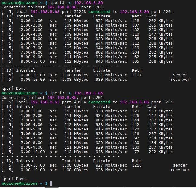
The iperf3 test between the four network ports can also run at full speed.
Note1: The four-port switch is a physical layer device, and is not visible in the system.
Note2:If there is no network cable plugged into the upstream router before booting up, even if you plug the cable later, you won't be able to access the network (IP address will be obtained an IP address as 169.254.xx.xx). You need to press the reset button on the switch (marked as Switch RST).
IV. Work with Ubuntu System
The process of loading network card drivers in Ubuntu 23.10 is relatively complex and cumbersome, and it is not recommended for use.
The version of the Ubuntu system is: ubuntu-24.04-preinstalled-desktop-arm64+raspi.img.xz
You can download the Ubuntu system in:
https://ubuntu.com/download/raspberry-pi
4.1 Install drivers
On Ubuntu 24.04, you can directly download driver source code and compile it. The steps are as follows:
Preparing the build environment:
sudo apt-get install --reinstall linux-headers-$(uname -r) linux-headers-generic build-essential dkms
Download and compile driver:
sudo apt install r8168-dkms
sudo modprobe r8168
4.2 Test network
Run the following command to view the wired network interface which is named enxxx:
ifconfig -a
http://www.mcuzone.com/wiki/0001_MPRG4/MPRG4_05.pngUsing iperf3 for speed testing, it can be run on gigabit speed.
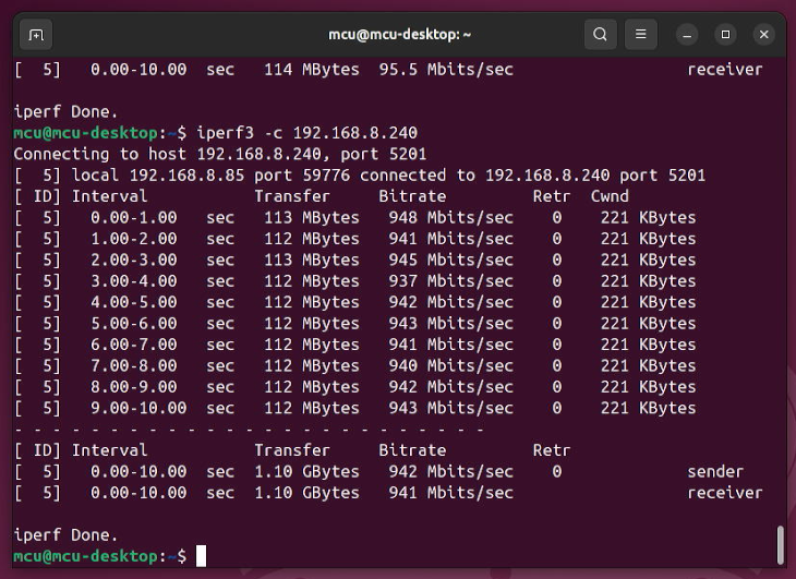
Note: On an Ubuntu system, the RTL8111H network card is recognized with a name like enxxxx, while the same switch used as a physical layer chip does not appear in the network card list.
V. Work with OpenWrt System
5.1 Overview
The MPRG4 expansion board can be configured in OpenWrt system as a switch with one input and four outputs. We can configure the Raspberry Pi's built-in Ethernet port as the WAN port, and use the four Ethernet ports on the expansion board as LAN ports, which can be used by other devices to obtain IP addresses within the same subnet.
System version: openwrt-bcm27xx-bcm2712-rpi-5-squashfs-sysupgrade-linux-6.1.92-20240530a.img.gz
5.2 Preparation
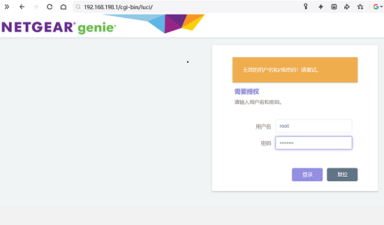
By default, the Raspberry Pi's built-in Ethernet port is configured as a LAN port. We can connect an Ethernet cable from the Raspberry Pi's built-in Ethernet port to the PC's Ethernet port. After powering on and booting the system, open a web browser and enter 192.168.198.1 to access the OpenWrt system.
Default username isroot, Default password ispassword.
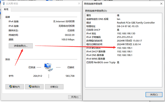
You can view the IP address of the connected network by opening the network in the "Network & Internet - Ethernet" settings in Windows.
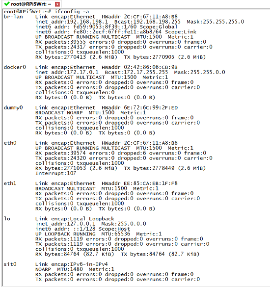
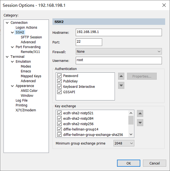
On the computer, use a terminal software (such as SecureCRT) to connect to the development board, and you will see that the network devices have been successfully recognized. By default, eth0 is configured as the LAN port, which is the Raspberry Pi's built-in Ethernet port. Here, it is set to bridge mode, and the network address can be found in br-lan.

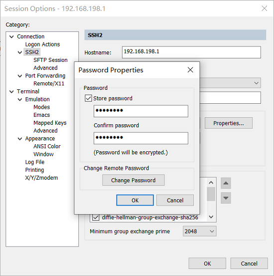
SecureCRT can be configured as follows:
5.3 Configure the OpenWrt system
After the device is properly recognized, we open the "network - interface".
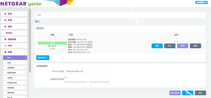
Then we click to add a new interface, set the name and interface protocol, and set the WAN port to eth0.
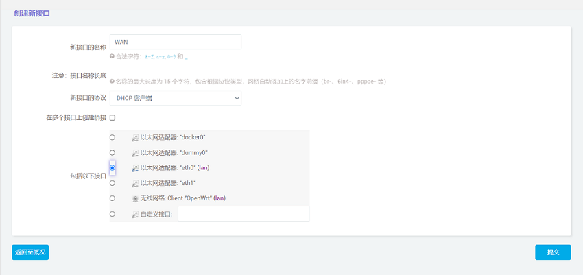
Click "Submit" and then select "WAN" in the firewall settings.
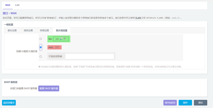
After setting it complete, click "Save". Be careful, do not click "Save & Apply", or you will not be able to enter the system.
Click "Back" to return to the overview, then click on LAN port modification.

Set the interface to eth1 in the "Physical Settings".
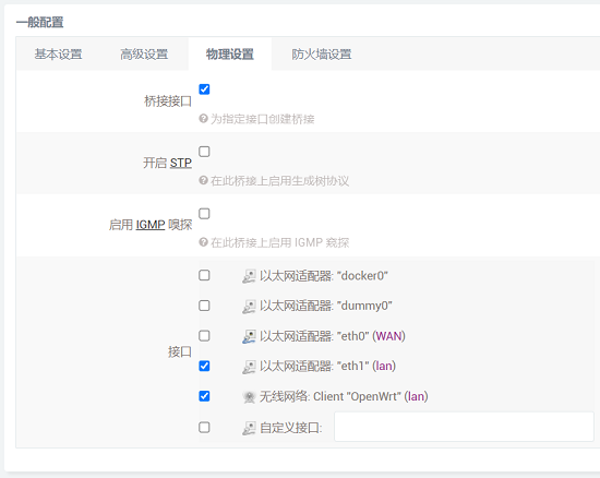
After setting up, we click "Save & Apply". Please note that since the network settings are being changed, it will continuously display "Applying changes". This is not a malfunction, and after waiting for a while, we can proceed to the next step.
5.4 Network test
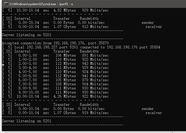
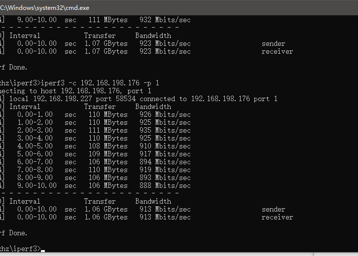
Restart the device and connect the new WAN port, which is the Raspberry Pi's built-in Ethernet port, to the upstream router. The four Ethernet ports on the expansion board will now act as LAN ports and can be used to connect other network devices to obtain network access. We'll connect two of the LAN ports to two PCs to simply test the network bandwidth.
Using iperf3 to test between two computers shows that the test results are normal.
VI. Radxa Rock 5C (RK3588S2) with MPRG4 expansion board
6.1 Overview
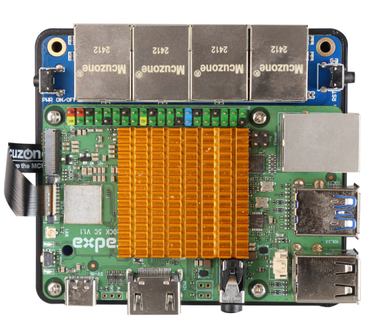
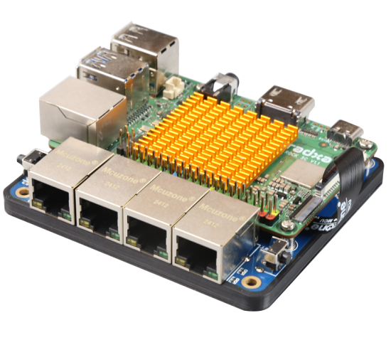
The Radxa Rock 5C is designed based on the RK3588S2, it have one gigabit ethernet port and four USB ports, along with a PCIe interface compatible with the Raspberry Pi 5. This interface allows us to expand with various PCIe extension boards originally designed for the Raspberry Pi 5. In this demonstration, we are using a four-network-port expansion board.
6.2 The software and hardware platform used in this demonstration
System version: debian bullseye kde b3, you can download it on github:
https://github.com/radxa-build/rock-5c/releases/
Expansion Board: MPRG4 Expansion Board with four ethernet ports.
6.3 Preparation
1. Connect the Rock 5C and the MPRG4.
2. Flashing the system to the TF card and inserting the card to boot, the default account login password is radxa.
2. Entering the system, find Konsole in the menu to access the terminal.
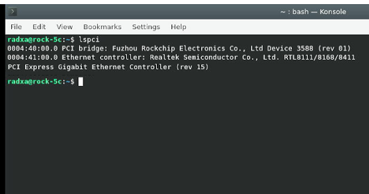
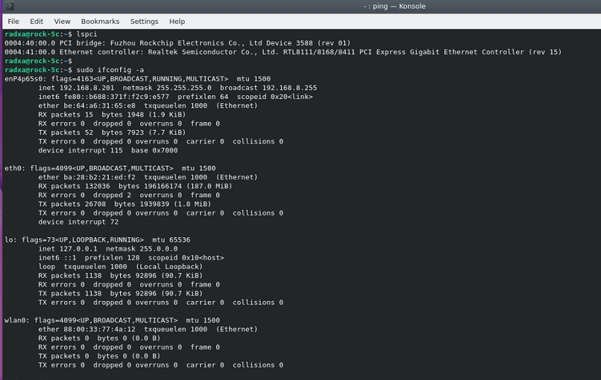
3. Execute lspci to ensure that the device information for RTL8111 is visible (if visible, it indicates that the expansion board hardware is functioning correctly; if not visible, check the reliability of the FPC connection. Note that the FPC cable has an orientation, and one side marked with RPi5 should be connected to Rock 5C).
4. Connect the network cable to the native gigabit port, then execute:
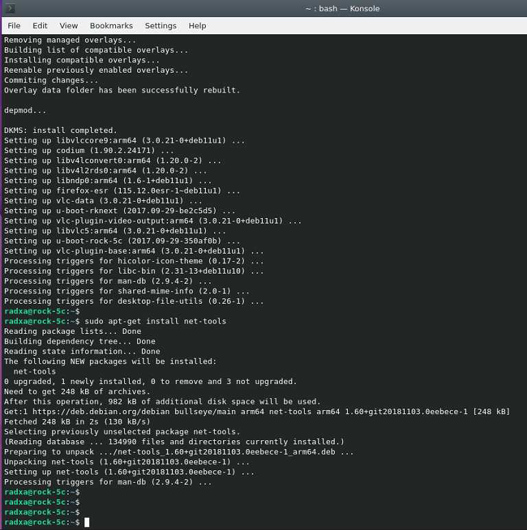
sudo apt-get update
sudo apt-get upgrade
sudo apt-get install net-tools
You can use the ifconfig after installing net-tools. Of course, you can also use other tools to operate the network.
6.4 Install drivers
1. Using DKMS to install the drivers.
sudo apt-get install r8168-dkms
sudo modprobe r8168
2. After installing the drivers, execute sudo ifconfig -a to check for network cards starting with 'enp', which indicates the RTL8111 network card. Note that the switch is a physical layer device and cannot be seen with ifconfig.
3. Confirm network connectivity by using ping packets:
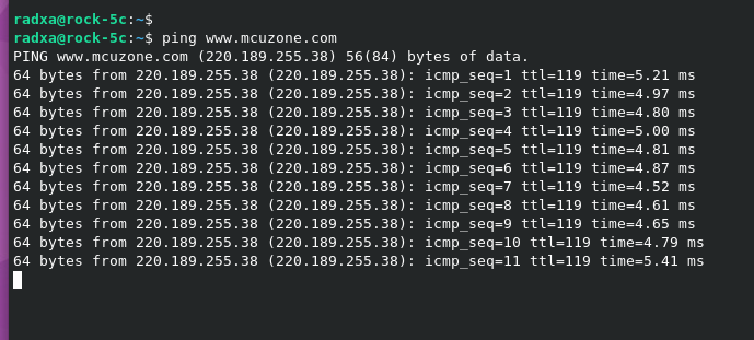
Now, the network card drivers has been successfully installed and is functioning normally.
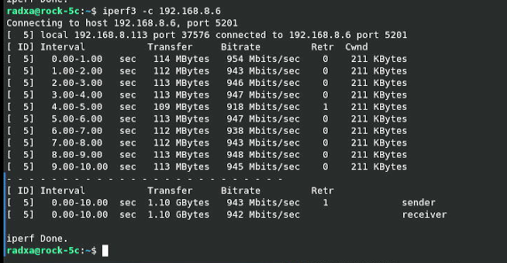
4. Using iperf3 for speed testing, it can be run on gigabit speed.
Contact Us
Email: mcuzone@vip.qq.com
Tel: +86(0)13957118045
If there are any omissions, errors, or infringements on this page, please contact us through the above methods. Thank you!
Copyright 2004-2024 Wildchip


 QQ:8204136