4001 R3S 4G EN:修订间差异
(创建页面,内容为“== '''关键词''' == 友善 NanoPi R3S、RK3566、4G LTE、FriendlyWrt、OpenWrt、Ubuntu == '''一、简介''' == R3S的4G是一款基于友善NanoPi R3S开发板设计的一款4G LTE套件。以我司CM4 4G mini(高通4G LTE)模块为基础,设计了R3S的4G载板和配套的3D打印底座而组成。3D打印底座是用于替代R3S外壳的底座,且将4G天线内置。4G模块在友善官方固件里免驱,自动识别,无需额外装驱动…”) |
小 (Mcuadm移动页面4001 R3S 4G (EN)至4001 R3S 4G EN) |
||
| (未显示同一用户的13个中间版本) | |||
| 第1行: | 第1行: | ||
[[4001 R3S 4G|切换语言为中文]] | |||
== ''' | == '''Keywords''' == | ||
FriendlyElec NanoPi R3S、RK3566、4G LTE、FriendlyWrt、OpenWrt、Ubuntu | |||
== '''I. Introduction''' == | |||
The 4G module for the R3S is a 4G LTE kit designed specifically for the FriendlyElec NanoPi R3S development board. It is based on our CM4 4G mini (Qualcomm 4G LTE) module, around which we have designed a 4G carrier board for the R3S along with a matching 3D-printed base to compose the set. The 3D printed base is designed to replace the R3S enclosure base and incorporates an integrated 4G antenna. The 4G module is supported out-of-the-box by the official Friendly firmware, with automatic detection and no need for additional driver installation. | |||
The 4G module is a USB device that connects to the USB port of the R3S. For customers who have purchased an integrated kit that includes both a 4G module and an R3S from our company, we can assist with modifications if required. The modification involves transforming the USB cable of the 4G module to be fully internal, eliminating the need for a USB adapter board. However, after this modification, the USB port on the R3S will no longer be able to connect to any other USB devices. | |||
http://www.mcuzone.com/wiki/4001_Friendly_NanoPi_R3S/4001_Friendly_NanoPi_R3S_47.jpg | http://www.mcuzone.com/wiki/4001_Friendly_NanoPi_R3S/4001_Friendly_NanoPi_R3S_47.jpg | ||
| 第12行: | 第14行: | ||
http://www.mcuzone.com/wiki/4001_Friendly_NanoPi_R3S/4001_Friendly_NanoPi_R3S_48.jpg | http://www.mcuzone.com/wiki/4001_Friendly_NanoPi_R3S/4001_Friendly_NanoPi_R3S_48.jpg | ||
http://www.mcuzone.com/wiki/4001_Friendly_NanoPi_R3S/4001_Friendly_NanoPi_R3S_130.jpg | |||
== '''II. Work with FriendlyWrt''' == | |||
The R3S development board comes in two versions: one without eMMC (which requires the system to be booted from a TF card), and another with eMMC (which allows the system to be booted either from the eMMC or from a TF card). All demonstrations in this document use the version that boots the system from a TF card. Different boot methods require corresponding different firmware packages. Please ensure that you match the correct firmware package to your boot method. | |||
The version of the FriendlyElec system we tested: rk3566-sd-friendlywrt-23.05-20240826.img.gz | |||
The 4G module is used as a WAN port in the FriendlyWrt system. Connect the R3S's LAN port to the PC's network port using an Ethernet cable. Open a web browser on the PC and navigate to 192.168.2.1 to log in to the FriendlyWrt system backend page (the default username is <code>root</code> and the password is <code>password</code>). | |||
=== 2.1 Test 4G module === | |||
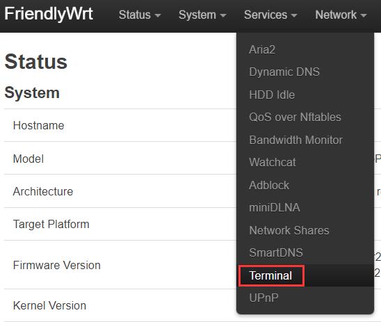
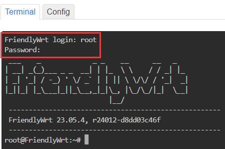
Navigate to Services - Terminal", log in to the terminal with the default username: <code>root</code> and password: <code>password</code>: | |||
http://www.mcuzone.com/wiki/4001_Friendly_NanoPi_R3S/ | http://www.mcuzone.com/wiki/4001_Friendly_NanoPi_R3S/4001_Friendly_NanoPi_R3S_108.jpg | ||
http://www.mcuzone.com/wiki/4001_Friendly_NanoPi_R3S/4001_Friendly_NanoPi_R3S_109.jpg | |||
Execute <code>ip addr</code>, and the result is as follows: | |||
http://www.mcuzone.com/wiki/4001_Friendly_NanoPi_R3S/4001_Friendly_NanoPi_R3S_36.jpg | http://www.mcuzone.com/wiki/4001_Friendly_NanoPi_R3S/4001_Friendly_NanoPi_R3S_36.jpg | ||
You can see usb0, which is our CM4 Qualcomm 4G LTE module. This indicates that the system has recognized the 4G module, but it has not yet obtained an IP address. | |||
To use the 4G module for internet access, you need to add a 4G interface. The steps are as follows: | |||
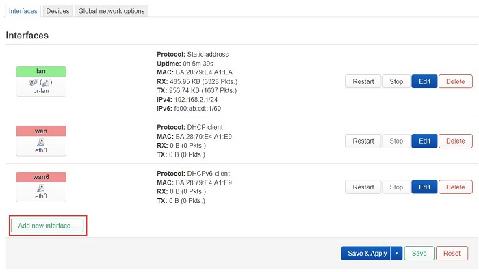
Navigate to "Network - Interfaces", and click on "Add new interface...": | |||
http://www.mcuzone.com/wiki/4001_Friendly_NanoPi_R3S/ | http://www.mcuzone.com/wiki/4001_Friendly_NanoPi_R3S/4001_Friendly_NanoPi_R3S_110.jpg | ||
Configure as shown in the figure below (the "Name" can be customized), select "usb0" for the "Device", and then click "Create interface": | |||
http://www.mcuzone.com/wiki/4001_Friendly_NanoPi_R3S/ | http://www.mcuzone.com/wiki/4001_Friendly_NanoPi_R3S/4001_Friendly_NanoPi_R3S_111.jpg | ||
Click on "Firewall Settings", in the "Create / Assign firewall-zone" section, select "wan", and then click "Save": | |||
http://www.mcuzone.com/wiki/4001_Friendly_NanoPi_R3S/ | http://www.mcuzone.com/wiki/4001_Friendly_NanoPi_R3S/4001_Friendly_NanoPi_R3S_112.jpg | ||
It automatically returns to the "Interfaces" page, then click "Save and Apply": | |||
http://www.mcuzone.com/wiki/4001_Friendly_NanoPi_R3S/ | http://www.mcuzone.com/wiki/4001_Friendly_NanoPi_R3S/4001_Friendly_NanoPi_R3S_113.jpg | ||
Wait for a moment, and we can see that the 4G module has obtained an IP address: | |||
http://www.mcuzone.com/wiki/4001_Friendly_NanoPi_R3S/ | http://www.mcuzone.com/wiki/4001_Friendly_NanoPi_R3S/4001_Friendly_NanoPi_R3S_114.jpg | ||
Back in the terminal, execute <code>ifconfig usb0</code> to check the network parameters of the 4G module: | |||
http://www.mcuzone.com/wiki/4001_Friendly_NanoPi_R3S/4001_Friendly_NanoPi_R3S_42.jpg | http://www.mcuzone.com/wiki/4001_Friendly_NanoPi_R3S/4001_Friendly_NanoPi_R3S_42.jpg | ||
A successful ping to the domain indicates that the 4G module is now able to browse the internet normally: | |||
http://www.mcuzone.com/wiki/4001_Friendly_NanoPi_R3S/4001_Friendly_NanoPi_R3S_43.jpg | http://www.mcuzone.com/wiki/4001_Friendly_NanoPi_R3S/4001_Friendly_NanoPi_R3S_43.jpg | ||
4G Module internet speed test: | |||
http://www.mcuzone.com/wiki/4001_Friendly_NanoPi_R3S/4001_Friendly_NanoPi_R3S_02.jpg | http://www.mcuzone.com/wiki/4001_Friendly_NanoPi_R3S/4001_Friendly_NanoPi_R3S_02.jpg | ||
''''' | '''''Note: Network speed testing is affected by the network environment and the testing method. The speed provided here is for reference only, please refer to the actual speed for accurate information.''''' | ||
=== 2.2 R3S with an external USB network adapter === | |||
The R3S comes equipped with two Ethernet ports. If a third Ethernet port is required, it can be added through the USB 3.0 port; however, this will disable the 4G functionality. We have tested that the R3S supports USB wired network adapters with the RTL8153 chipset, which can be used as a second LAN port. The procedure is as follows: | |||
Do not connect the USB wired network adapter first, let the system boot up normally and log in to the backend page. | |||
Insert the USB Ethernet adapter, wait for a moment, and then run <code>ifconfig -a</code> in the terminal. Once <code>eth2</code> appears in the output, it is ready: | |||
http://www.mcuzone.com/wiki/4001_Friendly_NanoPi_R3S/4001_Friendly_NanoPi_R3S_115.jpg | |||
Then navigate to "Network - Interfaces - Devices", and click "Configure..." behind "br-lan": | |||
http://www.mcuzone.com/wiki/4001_Friendly_NanoPi_R3S/4001_Friendly_NanoPi_R3S_116.jpg | |||
Click the arrow next to "Bridge ports", select both eth1 and eth2, and then click "Save": | |||
http://www.mcuzone.com/wiki/4001_Friendly_NanoPi_R3S/ | http://www.mcuzone.com/wiki/4001_Friendly_NanoPi_R3S/4001_Friendly_NanoPi_R3S_117.jpg | ||
After saving, return to the previous page and click "Save and Apply": | |||
http://www.mcuzone.com/wiki/4001_Friendly_NanoPi_R3S/ | http://www.mcuzone.com/wiki/4001_Friendly_NanoPi_R3S/4001_Friendly_NanoPi_R3S_118.jpg | ||
This sets the newly added USB Ethernet adapter as a LAN port, while the original built-in LAN port can still be used normally. | |||
=== 2.3 R3S with an external USB WiFi === | |||
The R3S has only one USB port, which can be used to connect an external USB WiFi adapter; however, in this case, the 4G functionality will not be available. For example, using an external RTL8812 USB wireless adapter: | |||
http://www.mcuzone.com/wiki/4001_Friendly_NanoPi_R3S/4001_Friendly_NanoPi_R3S_119.jpg | |||
http://www.mcuzone.com/wiki/4001_Friendly_NanoPi_R3S/ | http://www.mcuzone.com/wiki/4001_Friendly_NanoPi_R3S/4001_Friendly_NanoPi_R3S_120.jpg | ||
http://www.mcuzone.com/wiki/4001_Friendly_NanoPi_R3S/4001_Friendly_NanoPi_R3S_121.jpg | |||
http://www.mcuzone.com/wiki/4001_Friendly_NanoPi_R3S/4001_Friendly_NanoPi_R3S_122.jpg | |||
'''''Note: Connecting to the internet via a wireless network adapter can be unstable, and there might be an issue with not being able to find the AP.''''' | |||
<!-- | |||
The R3S has only one USB port, which can be used to connect an external USB WiFi adapter; however, in this case, the 4G functionality will not be available. For example, using an external MT7662 USB wireless adapter: | |||
http://www.mcuzone.com/wiki/4001_Friendly_NanoPi_R3S/4001_Friendly_NanoPi_R3S_04.jpg | http://www.mcuzone.com/wiki/4001_Friendly_NanoPi_R3S/4001_Friendly_NanoPi_R3S_04.jpg | ||
| 第100行: | 第116行: | ||
http://www.mcuzone.com/wiki/4001_Friendly_NanoPi_R3S/4001_Friendly_NanoPi_R3S_06.jpg | http://www.mcuzone.com/wiki/4001_Friendly_NanoPi_R3S/4001_Friendly_NanoPi_R3S_06.jpg | ||
'''''Note: Connecting to the internet via a wireless network adapter can be unstable, and there might be an issue with not being able to find the AP.''''' | |||
--> | |||
=== 2.4 | === 2.4 Other operations in FriendlyWrt === | ||
==== 2.4.1 Adblock ==== | ==== 2.4.1 Adblock ==== | ||
http://www.mcuzone.com/wiki/4001_Friendly_NanoPi_R3S/ | http://www.mcuzone.com/wiki/4001_Friendly_NanoPi_R3S/4001_Friendly_NanoPi_R3S_123.jpg | ||
==== 2.4.2 | ==== 2.4.2 Statistics ==== | ||
Such as temperature control statistics, processor statistics, etc.: | |||
http://www.mcuzone.com/wiki/4001_Friendly_NanoPi_R3S/ | http://www.mcuzone.com/wiki/4001_Friendly_NanoPi_R3S/4001_Friendly_NanoPi_R3S_124.jpg | ||
http://www.mcuzone.com/wiki/4001_Friendly_NanoPi_R3S/ | http://www.mcuzone.com/wiki/4001_Friendly_NanoPi_R3S/4001_Friendly_NanoPi_R3S_125.jpg | ||
== ''' | == '''III. Work with Ubuntu OS''' == | ||
The R3S development board comes in two versions: one without eMMC (which requires the system to be booted from a TF card), and another with eMMC (which allows the system to be booted either from the eMMC or from a TF card). All demonstrations in this document use the version that boots the system from a TF card. Different boot methods require corresponding different firmware packages. Please ensure that you match the correct firmware package to your boot method. | |||
=== 3.1 | === 3.1 Test the 4G module === | ||
Flash the Ubuntu system (command-line version, without a GUI) to the TF card. | |||
The version of the FriendlyElec system we tested: rk3566-sd-ubuntu-noble-core-6.1-arm64-20241114.img.gz | |||
Connect the LAN port of the R3S to the upstream router using an Ethernet cable, then connect the PC to the same upstream router. Insert the SIM card and the TF card with the pre-installed system into the R3S. After the system boots, check the IP address of the R3S through the router's backend. In this document, the address obtained by the system is: 192.168.8.35. | |||
Download and install the terminal software MobaXterm on your PC. The download link for MobaXterm is: | |||
https://mobaxterm.mobatek.net/download-home-edition.html | https://mobaxterm.mobatek.net/download-home-edition.html | ||
Then use MobaXterm to connect to the system via SSH (username: <code>root</code>, password: <code>fa</code>): | |||
http://www.mcuzone.com/wiki/4001_Friendly_NanoPi_R3S/4001_Friendly_NanoPi_R3S_27.jpg | http://www.mcuzone.com/wiki/4001_Friendly_NanoPi_R3S/4001_Friendly_NanoPi_R3S_27.jpg | ||
| 第134行: | 第151行: | ||
http://www.mcuzone.com/wiki/4001_Friendly_NanoPi_R3S/4001_Friendly_NanoPi_R3S_28.jpg | http://www.mcuzone.com/wiki/4001_Friendly_NanoPi_R3S/4001_Friendly_NanoPi_R3S_28.jpg | ||
Excecute <code>ifconfig -a</code> to view the following network parameters: | |||
http://www.mcuzone.com/wiki/4001_Friendly_NanoPi_R3S/4001_Friendly_NanoPi_R3S_29.jpg | http://www.mcuzone.com/wiki/4001_Friendly_NanoPi_R3S/4001_Friendly_NanoPi_R3S_29.jpg | ||
eth0 is the WAN port of the R3S, and since it is not connected to a network cable, it does not have an IP address. | |||
eth1 is the LAN port of the R3S, connected to the upstream router, and it has correctly obtained an IP address. | |||
usb0 is the 4G module, which has correctly obtained an IP address. | |||
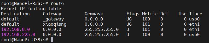
Execute <code>route</code> to view the routing table. Since usb0 is listed first, it indicates that the internet connection is currently through the 4G module: | |||
http://www.mcuzone.com/wiki/4001_Friendly_NanoPi_R3S/4001_Friendly_NanoPi_R3S_30.jpg | http://www.mcuzone.com/wiki/4001_Friendly_NanoPi_R3S/4001_Friendly_NanoPi_R3S_30.jpg | ||
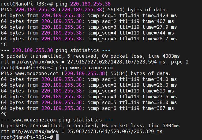
At this point, when we ping the IP address and the domain name, both are successful, indicating that the 4G module is working properly: | |||
http://www.mcuzone.com/wiki/4001_Friendly_NanoPi_R3S/4001_Friendly_NanoPi_R3S_31.jpg | http://www.mcuzone.com/wiki/4001_Friendly_NanoPi_R3S/4001_Friendly_NanoPi_R3S_31.jpg | ||
=== 3.2 | === 3.2 Modification of Network Priority === | ||
The Ubuntu system on the R3S, prioritizes connecting to the internet through the 4G network by default,. | |||
If you want to prioritize the wired network for internet access, you can execute the following command: | |||
<code>sudo ip route del default && sudo route add -net default netmask 0.0.0.0 gw 192.168.8.1</code> | <code>sudo ip route del default && sudo route add -net default netmask 0.0.0.0 gw 192.168.8.1</code> | ||
Explanation of these two commands (separated by '&&'): | |||
<code>sudo ip route del default</code> | <code>sudo ip route del default</code>: Remove the default route from the routing table. | ||
<code>sudo route add -net default netmask 0.0.0.0 gw 192.168.8.1</code> | <code>sudo route add -net default netmask 0.0.0.0 gw 192.168.8.1</code>: Add the gateway of the wired network as a new default route (ensure to use the actual gateway address). | ||
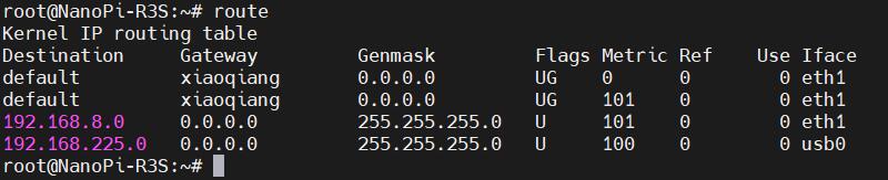
After completing the execution, execute the <code>route</code> command to view the routing table. The current default route is the gateway of the wired network (eth1 is listed first): | |||
http://www.mcuzone.com/wiki/4001_Friendly_NanoPi_R3S/4001_Friendly_NanoPi_R3S_32.jpg | http://www.mcuzone.com/wiki/4001_Friendly_NanoPi_R3S/4001_Friendly_NanoPi_R3S_32.jpg | ||
This way, the network will default to using the wired connection. If you need to switch back to defaulting to the 4G network, please execute the following command: | |||
<code>sudo ip route del default && sudo route add -net default netmask 0.0.0.0 gw 192.168.225.1</code> | <code>sudo ip route del default && sudo route add -net default netmask 0.0.0.0 gw 192.168.225.1</code> | ||
Or, you can restart the system. | |||
Note that 192.168.225.1 is the default gateway for the 4G module; please refer to the actual configuration. | |||
''''' | '''''Note: After a reboot, the routing table resets. To ensure the network continues to use the wired or wireless connection as the default route post-restart, you'll need to execute <code>sudo ip route del default && sudo route add -net default netmask 0.0.0.0 gw 192.168.8.1</code> again.''''' | ||
=== 3.3 | === 3.3 AT command operation === | ||
Please install usbutils first: | |||
<code>apt install usbutils</code> | <code>apt install usbutils</code> | ||
Use <code>lsusb</code> to view USB devices, the red-boxed entry indicates the 4G module: | |||
http://www.mcuzone.com/wiki/4001_Friendly_NanoPi_R3S/4001_Friendly_NanoPi_R3S_33.jpg | http://www.mcuzone.com/wiki/4001_Friendly_NanoPi_R3S/4001_Friendly_NanoPi_R3S_33.jpg | ||
Note down the ID value of the 4G module: 05c6 90b6. | |||
Use the following command to enable the ttyUSB serial port of the 4G module, where the value after echo is the ID value recorded earlier: | |||
<code>modprobe option</code> | <code>modprobe option</code> | ||
| 第196行: | 第213行: | ||
<code>sh -c 'echo 05c6 90b6 > /sys/bus/usb-serial/drivers/option1/new_id'</code> | <code>sh -c 'echo 05c6 90b6 > /sys/bus/usb-serial/drivers/option1/new_id'</code> | ||
After executing the above two commands, execute the following: | |||
<code>ls /dev</code> | <code>ls /dev</code> | ||
At this point, you should be able to see three devices under the dev directory: ttyUSB0, ttyUSB1, ttyUSB2. | |||
http://www.mcuzone.com/wiki/4001_Friendly_NanoPi_R3S/4001_Friendly_NanoPi_R3S_34.jpg | http://www.mcuzone.com/wiki/4001_Friendly_NanoPi_R3S/4001_Friendly_NanoPi_R3S_34.jpg | ||
Install the serial port software minicom: | |||
<code>apt install minicom</code> | <code>apt install minicom</code> | ||
Open the AT command serial port using minicom: | |||
<code>minicom -D /dev/ttyUSB0</code> | <code>minicom -D /dev/ttyUSB0</code> | ||
(Note: Which serial port to use should be determined by the ability to enter and execute AT commands without garbled or erratic output after accessing that serial port.) | |||
If you need to view echo responses, type the command: <code>ate1</code>, then press Enter. You can continue to type other commands, and after pressing Enter, you will see the results. | |||
http://www.mcuzone.com/wiki/4001_Friendly_NanoPi_R3S/4001_Friendly_NanoPi_R3S_35.jpg | http://www.mcuzone.com/wiki/4001_Friendly_NanoPi_R3S/4001_Friendly_NanoPi_R3S_35.jpg | ||
Common AT commands: | |||
1 | 1) Check if the SIM card is detected: | ||
<code>at+cpin?</code> | <code>at+cpin?</code> | ||
Return ready to indicate the card has been recognized, if return error, you need to check the hardware. | |||
2 | 2) Check antenna signal quality: | ||
<code>at+csq</code> | <code>at+csq</code> | ||
eturn values between 26 and 31 indicate a good signal, with 31 representing a full signal strength; return values between 20 and 25 indicate a barely acceptable signal; return values below 20 indicate a poor signal or that the antenna might not be connected. | |||
3 | 3) Check network registration status: | ||
<code>at+cops?</code> | <code>at+cops?</code> | ||
Normally, it should return the network supporter's code: 7, where 7 represents 4G. | |||
Note: The above command <code>at+csq</code> should not include a question mark, while the other two commands require a question mark. | |||
4 | 4) View the SIM card's IMEI code: | ||
<code>at+cgsn</code> | <code>at+cgsn</code> | ||
5. | 5) Reset 4G module (Sometimes, if you reinsert the SIM card, hot swapping may not work; in such cases, you can use this reset command to reset the module.): | ||
<code>at+reset</code> | <code>at+reset</code> | ||
6 | 6) Disable radio frequency: | ||
<code>at+cfun=0</code> | <code>at+cfun=0</code> | ||
Enable radio frequency: | |||
<code>at+cfun=1</code> | <code>at+cfun=1</code> | ||
The two commands mentioned above can be used in pairs to allow the module to re-register with the network without restarting the 4G module. | |||
=== 3.4 | === 3.4 Modify the IP address of the 4G module === | ||
If the default 4G IP address assigned at the factory conflicts with the IP address being used by the user, or if there is a need to modify the IP address, you can change the 4G module's IP to directly obtain a public IP. Please execute the AT command: | |||
Set the 4G module's IP to directly obtain a public IP. Please execute the AT command: | |||
Set the IP to public: <code>AT+GTIPPASS=1</code> | |||
Set the IP to private: <code>AT+GTIPPASS=0</code> | |||
Check whether the current IP is a public or private IP:<code>AT+GTIPPASS?</code> | |||
== ''' | |||
After modifying the IP, a power cycle reboot is required for the changes to take effect. | |||
== '''IV. Summary''' == | |||
We only introduce the usage and operations for 4G module based on NanoPi R3S, without covering the operations and software system specific to the NanoPi R3S development board itself. For information about the NanoPi R3S boards, please visit the FriendlyElec official website: | |||
https://wiki.friendlyelec.com/wiki/index.php/NanoPi_R3S/zh | https://wiki.friendlyelec.com/wiki/index.php/NanoPi_R3S/zh | ||
{{ | {{Contact_Us_icon}} | ||
[http://wiki.mcuzone.com/index.php?title=4001_R3S_4G_(EN) T] | |||
2024年12月26日 (四) 15:32的最新版本
Keywords
FriendlyElec NanoPi R3S、RK3566、4G LTE、FriendlyWrt、OpenWrt、Ubuntu
I. Introduction
The 4G module for the R3S is a 4G LTE kit designed specifically for the FriendlyElec NanoPi R3S development board. It is based on our CM4 4G mini (Qualcomm 4G LTE) module, around which we have designed a 4G carrier board for the R3S along with a matching 3D-printed base to compose the set. The 3D printed base is designed to replace the R3S enclosure base and incorporates an integrated 4G antenna. The 4G module is supported out-of-the-box by the official Friendly firmware, with automatic detection and no need for additional driver installation.
The 4G module is a USB device that connects to the USB port of the R3S. For customers who have purchased an integrated kit that includes both a 4G module and an R3S from our company, we can assist with modifications if required. The modification involves transforming the USB cable of the 4G module to be fully internal, eliminating the need for a USB adapter board. However, after this modification, the USB port on the R3S will no longer be able to connect to any other USB devices.


II. Work with FriendlyWrt
The R3S development board comes in two versions: one without eMMC (which requires the system to be booted from a TF card), and another with eMMC (which allows the system to be booted either from the eMMC or from a TF card). All demonstrations in this document use the version that boots the system from a TF card. Different boot methods require corresponding different firmware packages. Please ensure that you match the correct firmware package to your boot method.
The version of the FriendlyElec system we tested: rk3566-sd-friendlywrt-23.05-20240826.img.gz
The 4G module is used as a WAN port in the FriendlyWrt system. Connect the R3S's LAN port to the PC's network port using an Ethernet cable. Open a web browser on the PC and navigate to 192.168.2.1 to log in to the FriendlyWrt system backend page (the default username is root and the password is password).
2.1 Test 4G module
Navigate to Services - Terminal", log in to the terminal with the default username: root and password: password:
Execute ip addr, and the result is as follows:
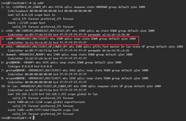
You can see usb0, which is our CM4 Qualcomm 4G LTE module. This indicates that the system has recognized the 4G module, but it has not yet obtained an IP address.
To use the 4G module for internet access, you need to add a 4G interface. The steps are as follows:
Navigate to "Network - Interfaces", and click on "Add new interface...":
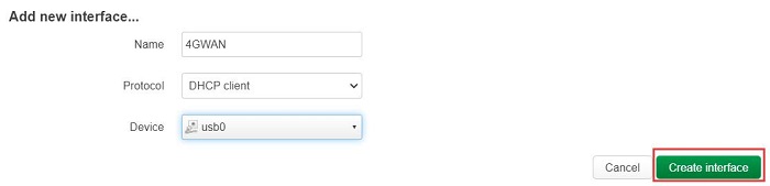
Configure as shown in the figure below (the "Name" can be customized), select "usb0" for the "Device", and then click "Create interface":
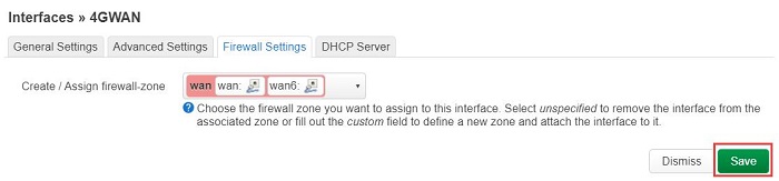
Click on "Firewall Settings", in the "Create / Assign firewall-zone" section, select "wan", and then click "Save":
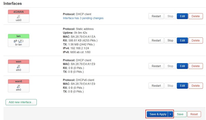
It automatically returns to the "Interfaces" page, then click "Save and Apply":
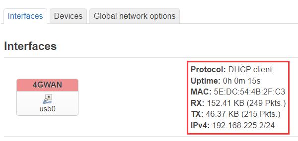
Wait for a moment, and we can see that the 4G module has obtained an IP address:
Back in the terminal, execute ifconfig usb0 to check the network parameters of the 4G module:
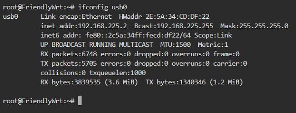
A successful ping to the domain indicates that the 4G module is now able to browse the internet normally:

4G Module internet speed test:
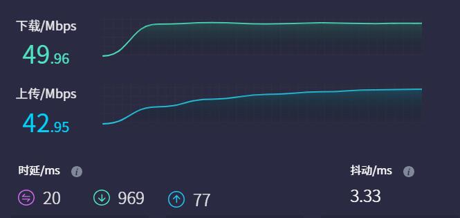
Note: Network speed testing is affected by the network environment and the testing method. The speed provided here is for reference only, please refer to the actual speed for accurate information.
2.2 R3S with an external USB network adapter
The R3S comes equipped with two Ethernet ports. If a third Ethernet port is required, it can be added through the USB 3.0 port; however, this will disable the 4G functionality. We have tested that the R3S supports USB wired network adapters with the RTL8153 chipset, which can be used as a second LAN port. The procedure is as follows:
Do not connect the USB wired network adapter first, let the system boot up normally and log in to the backend page.
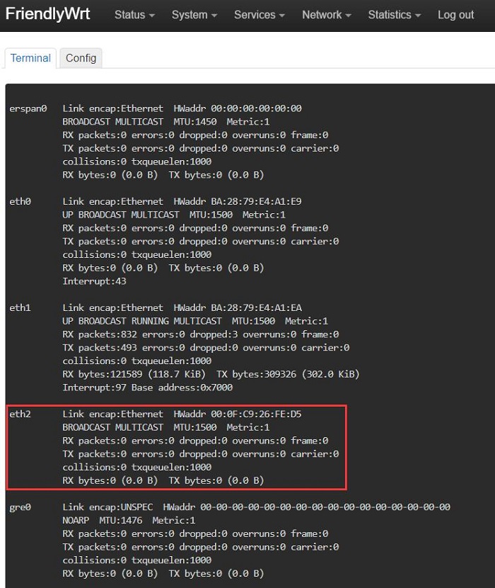
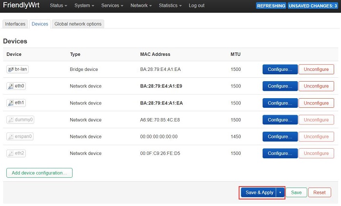
Insert the USB Ethernet adapter, wait for a moment, and then run ifconfig -a in the terminal. Once eth2 appears in the output, it is ready:
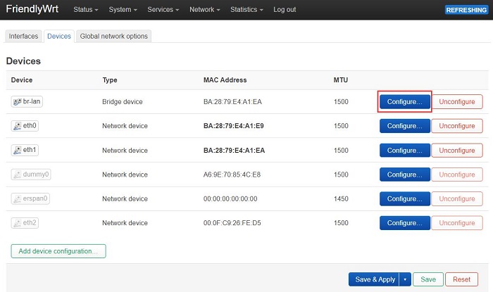
Then navigate to "Network - Interfaces - Devices", and click "Configure..." behind "br-lan":
Click the arrow next to "Bridge ports", select both eth1 and eth2, and then click "Save":
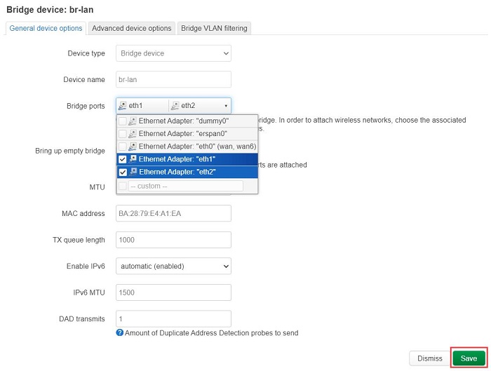
After saving, return to the previous page and click "Save and Apply":
This sets the newly added USB Ethernet adapter as a LAN port, while the original built-in LAN port can still be used normally.
2.3 R3S with an external USB WiFi
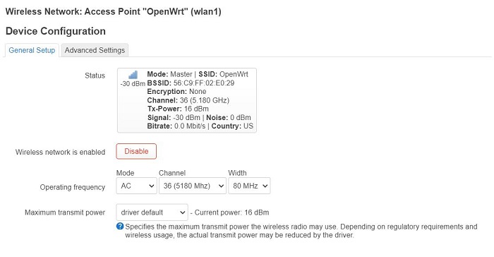
The R3S has only one USB port, which can be used to connect an external USB WiFi adapter; however, in this case, the 4G functionality will not be available. For example, using an external RTL8812 USB wireless adapter:
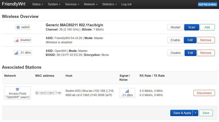
Note: Connecting to the internet via a wireless network adapter can be unstable, and there might be an issue with not being able to find the AP.
2.4 Other operations in FriendlyWrt
2.4.1 Adblock

2.4.2 Statistics
Such as temperature control statistics, processor statistics, etc.:


III. Work with Ubuntu OS
The R3S development board comes in two versions: one without eMMC (which requires the system to be booted from a TF card), and another with eMMC (which allows the system to be booted either from the eMMC or from a TF card). All demonstrations in this document use the version that boots the system from a TF card. Different boot methods require corresponding different firmware packages. Please ensure that you match the correct firmware package to your boot method.
3.1 Test the 4G module
Flash the Ubuntu system (command-line version, without a GUI) to the TF card.
The version of the FriendlyElec system we tested: rk3566-sd-ubuntu-noble-core-6.1-arm64-20241114.img.gz
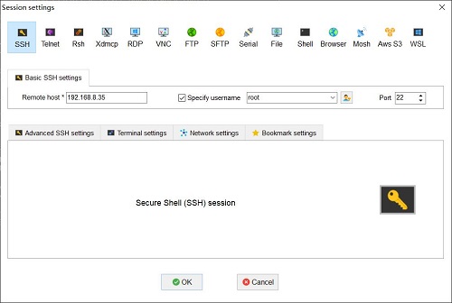
Connect the LAN port of the R3S to the upstream router using an Ethernet cable, then connect the PC to the same upstream router. Insert the SIM card and the TF card with the pre-installed system into the R3S. After the system boots, check the IP address of the R3S through the router's backend. In this document, the address obtained by the system is: 192.168.8.35.
Download and install the terminal software MobaXterm on your PC. The download link for MobaXterm is:
https://mobaxterm.mobatek.net/download-home-edition.html
Then use MobaXterm to connect to the system via SSH (username: root, password: fa):
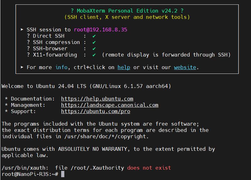
Excecute ifconfig -a to view the following network parameters:

eth0 is the WAN port of the R3S, and since it is not connected to a network cable, it does not have an IP address.
eth1 is the LAN port of the R3S, connected to the upstream router, and it has correctly obtained an IP address.
usb0 is the 4G module, which has correctly obtained an IP address.
Execute route to view the routing table. Since usb0 is listed first, it indicates that the internet connection is currently through the 4G module:
At this point, when we ping the IP address and the domain name, both are successful, indicating that the 4G module is working properly:
3.2 Modification of Network Priority
The Ubuntu system on the R3S, prioritizes connecting to the internet through the 4G network by default,.
If you want to prioritize the wired network for internet access, you can execute the following command:
sudo ip route del default && sudo route add -net default netmask 0.0.0.0 gw 192.168.8.1
Explanation of these two commands (separated by '&&'):
sudo ip route del default: Remove the default route from the routing table.
sudo route add -net default netmask 0.0.0.0 gw 192.168.8.1: Add the gateway of the wired network as a new default route (ensure to use the actual gateway address).
After completing the execution, execute the route command to view the routing table. The current default route is the gateway of the wired network (eth1 is listed first):
This way, the network will default to using the wired connection. If you need to switch back to defaulting to the 4G network, please execute the following command:
sudo ip route del default && sudo route add -net default netmask 0.0.0.0 gw 192.168.225.1
Or, you can restart the system.
Note that 192.168.225.1 is the default gateway for the 4G module; please refer to the actual configuration.
Note: After a reboot, the routing table resets. To ensure the network continues to use the wired or wireless connection as the default route post-restart, you'll need to execute sudo ip route del default && sudo route add -net default netmask 0.0.0.0 gw 192.168.8.1 again.
3.3 AT command operation
Please install usbutils first:
apt install usbutils
Use lsusb to view USB devices, the red-boxed entry indicates the 4G module:
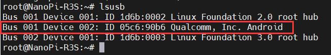
Note down the ID value of the 4G module: 05c6 90b6.
Use the following command to enable the ttyUSB serial port of the 4G module, where the value after echo is the ID value recorded earlier:
modprobe option
sh -c 'echo 05c6 90b6 > /sys/bus/usb-serial/drivers/option1/new_id'
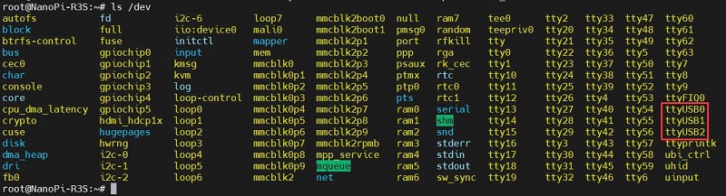
After executing the above two commands, execute the following:
ls /dev
At this point, you should be able to see three devices under the dev directory: ttyUSB0, ttyUSB1, ttyUSB2.
Install the serial port software minicom:
apt install minicom
Open the AT command serial port using minicom:
minicom -D /dev/ttyUSB0
(Note: Which serial port to use should be determined by the ability to enter and execute AT commands without garbled or erratic output after accessing that serial port.)
If you need to view echo responses, type the command: ate1, then press Enter. You can continue to type other commands, and after pressing Enter, you will see the results.
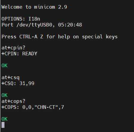
Common AT commands:
1) Check if the SIM card is detected:
at+cpin?
Return ready to indicate the card has been recognized, if return error, you need to check the hardware.
2) Check antenna signal quality:
at+csq
eturn values between 26 and 31 indicate a good signal, with 31 representing a full signal strength; return values between 20 and 25 indicate a barely acceptable signal; return values below 20 indicate a poor signal or that the antenna might not be connected.
3) Check network registration status:
at+cops?
Normally, it should return the network supporter's code: 7, where 7 represents 4G.
Note: The above command at+csq should not include a question mark, while the other two commands require a question mark.
4) View the SIM card's IMEI code:
at+cgsn
5) Reset 4G module (Sometimes, if you reinsert the SIM card, hot swapping may not work; in such cases, you can use this reset command to reset the module.):
at+reset
6) Disable radio frequency:
at+cfun=0
Enable radio frequency:
at+cfun=1
The two commands mentioned above can be used in pairs to allow the module to re-register with the network without restarting the 4G module.
3.4 Modify the IP address of the 4G module
If the default 4G IP address assigned at the factory conflicts with the IP address being used by the user, or if there is a need to modify the IP address, you can change the 4G module's IP to directly obtain a public IP. Please execute the AT command:
Set the 4G module's IP to directly obtain a public IP. Please execute the AT command:
Set the IP to public: AT+GTIPPASS=1
Set the IP to private: AT+GTIPPASS=0
Check whether the current IP is a public or private IP:AT+GTIPPASS?
After modifying the IP, a power cycle reboot is required for the changes to take effect.
IV. Summary
We only introduce the usage and operations for 4G module based on NanoPi R3S, without covering the operations and software system specific to the NanoPi R3S development board itself. For information about the NanoPi R3S boards, please visit the FriendlyElec official website:
https://wiki.friendlyelec.com/wiki/index.php/NanoPi_R3S/zh
Contact Us


 QQ:8204136
Email: mcuzone@vip.qq.com
Tel: +86(0)13957118045
If there are any omissions, errors, or infringements on this page, please contact us through the above methods. Thank you!
Copyright 2004-2025 Wildchip