3002 21700 5V3A Power Bank:修订间差异
无编辑摘要 |
无编辑摘要 |
||
| (未显示同一用户的4个中间版本) | |||
| 第37行: | 第37行: | ||
=== 2. Product Features === | === 2. Product Features === | ||
* | *The MCU is used for power management and supports serial output, which is used to indicate the battery voltage and output voltage. | ||
* | *Two MOSFETs are used for output control, supporting low-voltage shutdown. They also support manual or serial command control for turning the output on or off. | ||
* | *Charge head (input) detection function. | ||
=== 3. Serial port output characteristics === | === 3. Serial port output characteristics === | ||
* | *The system automatically reports the battery voltage and output voltage, enabling the host system to estimate the system's runtime and prepare for data protection in advance. The reporting interval can be set via a command, with a default interval of 2 seconds. | ||
* | *Automatically illuminate the battery level indicator LEDs for easy observation. The illumination interval can be set via a command, with a default of 1 minute. | ||
* | *The low-voltage protection threshold for the battery can be set, with a default setting of 3V to shut off the output. | ||
* | *The system can query the total uptime since power-on. | ||
* | *The system can turn off or turn on the two output channels via commands. | ||
* | *The system allows setting a button to control either one or both output channels. | ||
: | :Note: Current sampling is not supported. | ||
The serial cable is used for data transmission and should be connected as shown in the following diagram: | |||
http://www.mcuzone.com/wiki/3002_21700_Power_Supply/3002_21700_Power_Supply_32.jpg | http://www.mcuzone.com/wiki/3002_21700_Power_Supply/3002_21700_Power_Supply_32.jpg | ||
=== 4. Battery Description === | === 4. Battery Description === | ||
This product uses two 21700 lithium-ion power batteries in parallel to provide power, offering long-lasting operation with a reliable discharge capability of over 10A, ensuring sufficient power for dual outputs of 5V2A and 5V4A. Switch-mode charging is used, so even if the charging current reaches 2.8A, neither the chip nor the battery will trigger overheat protection. It is recommended to use an adapter with an output capability of 5V2.5A or higher for charging. If the adapter cannot meet the 2.5A output requirement, it may result in the charger's protection mechanism kicking in (preventing charging) or even cause damage. | |||
Battery polarity and installation instructions: | |||
http://www.mcuzone.com/wiki/3002_21700_Power_Supply/3002_21700_Power_Supply_33.jpg | http://www.mcuzone.com/wiki/3002_21700_Power_Supply/3002_21700_Power_Supply_33.jpg | ||
The 21700 battery has a large energy capacity. Please make sure to carefully check the orientation before inserting it into the battery holder. If inserted incorrectly, there is a risk of smoking, fire, or even explosion. For everyone's safety, please verify carefully before inserting. Do not plug or unplug unless necessary! | |||
We will not be liable for any risks resulting from incorrect battery connection. Please use with caution. Additionally, damage to components caused by incorrect battery connection is not covered under warranty. | |||
Damage caused to the battery or device due to charging with a user-supplied power adapter is not covered under warranty. Please use high-quality, genuine power supplies, or purchase one from our company. | |||
=== 5. Power indication and output control === | === 5. Power indication and output control === | ||
The remaining battery level can be checked by pressing the battery level detection button: | |||
http://www.mcuzone.com/wiki/3002_21700_Power_Supply/3002_21700_Power_Supply_34.jpg | http://www.mcuzone.com/wiki/3002_21700_Power_Supply/3002_21700_Power_Supply_34.jpg | ||
The output control button can be used to control the output of USB1 or USB2:http://www.mcuzone.com/wiki/3002_21700_Power_Supply/3002_21700_Power_Supply_35.jpg | |||
http://www.mcuzone.com/wiki/3002_21700_Power_Supply/3002_21700_Power_Supply_35.jpg | |||
=== 6. Dual output application === | === 6. Dual output application === | ||
One of the key features of this product is its support for dual output: | |||
One output is 5V2A, which is always on; it can connect to three external devices simultaneously and also supports simultaneous charging and discharging, meaning one input and two outputs. Whether connecting two or three outputs simultaneously, they all share 5V2A. | |||
One output is a high-power 5V4A output, featuring a pogo pin interface and two USB-A ports. Therefore, if using the probe version, this output port can simultaneously connect to 3 devices, sharing 5V4A. | |||
This product can connect up to six devices simultaneously; if charging and discharging at the same time, it can connect up to five devices simultaneously. It supports the simultaneous operation of a Raspberry Pi, 4G module, servos, radar modules, and more using the same power module, solving power supply issues. | |||
http://www.mcuzone.com/wiki/3002_21700_Power_Supply/3002_21700_Power_Supply_36.jpg | http://www.mcuzone.com/wiki/3002_21700_Power_Supply/3002_21700_Power_Supply_36.jpg | ||
== ''' | == '''III. Interactive serial port(Raspberry Pi OS)''' == | ||
The version of the Raspberry Pi OS is: 2024-10-22-raspios-bookworm-armhf.img.xz | |||
You can download the Raspberry Pi OS in: | |||
https://www.raspberrypi.com/software/operating-systems/#raspberry-pi-os-64-bit | https://www.raspberrypi.com/software/operating-systems/#raspberry-pi-os-64-bit | ||
=== 3.1 | === 3.1 Configure Raspberry Pi OS === | ||
The Raspberry Pi logo in the upper left corner — Preferences — Raspberry Pi Configuration — Interfaces | |||
Enable "Serial Port", disable "Serial Console", as shown in the figure: | |||
http://www.mcuzone.com/wiki/3002_21700_Power_Supply/3002_21700_Power_Supply_19.jpg | http://www.mcuzone.com/wiki/3002_21700_Power_Supply/3002_21700_Power_Supply_19.jpg | ||
This completes the serial port configuration. | |||
=== 3.2 | === 3.2 View real-time power parameters === | ||
Use serial commands for interaction, serial communication software such as minicom or CuteCom can be used. The installation commands are as follows: | |||
<code>sudo apt install minicom</code> | <code>sudo apt install minicom</code> | ||
| 第117行: | 第115行: | ||
<code>sudo apt install cutecom</code> | <code>sudo apt install cutecom</code> | ||
Under the Raspberry Pi OS, the interactive serial port is ttyS0 (note that S is uppercase). | |||
==== 3.2.1 | ==== 3.2.1 Use minicom ==== | ||
Open the Raspberry Pi terminal and run minicom: | |||
<code>sudo minicom -D /dev/ttyS0</code> | <code>sudo minicom -D /dev/ttyS0</code> | ||
You will then see the interactive information: | |||
http://www.mcuzone.com/wiki/3002_21700_Power_Supply/3002_21700_Power_Supply_15.jpg | http://www.mcuzone.com/wiki/3002_21700_Power_Supply/3002_21700_Power_Supply_15.jpg | ||
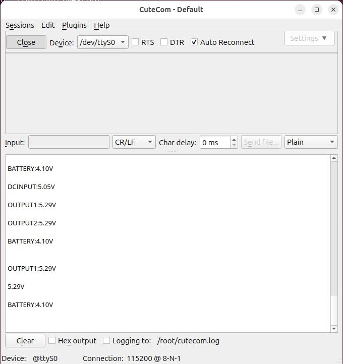
DCINPUT: DC input voltage | |||
OUTPUT1: Output voltage 1 | |||
OUTPUT2: Output voltage 2 | |||
BATTERY: Battery voltage | |||
==== 3.2.2 | ==== 3.2.2 Use CuteCom ==== | ||
Run the CuteCom, open the ttyS0 serial port, and view the interaction information in the output window: | |||
http://www.mcuzone.com/wiki/3002_21700_Power_Supply/3002_21700_Power_Supply_16.jpg | http://www.mcuzone.com/wiki/3002_21700_Power_Supply/3002_21700_Power_Supply_16.jpg | ||
=== 3.3 | === 3.3 Run the power system control commands === | ||
Run the CuteCom, open the ttyS0 serial port, enter commands in the Input window, and view the corresponding return information in the Output window. | |||
For example, <code>ATE</code> indicates that query the total system uptime: | |||
http://www.mcuzone.com/wiki/3002_21700_Power_Supply/3002_21700_Power_Supply_17.jpg | http://www.mcuzone.com/wiki/3002_21700_Power_Supply/3002_21700_Power_Supply_17.jpg | ||
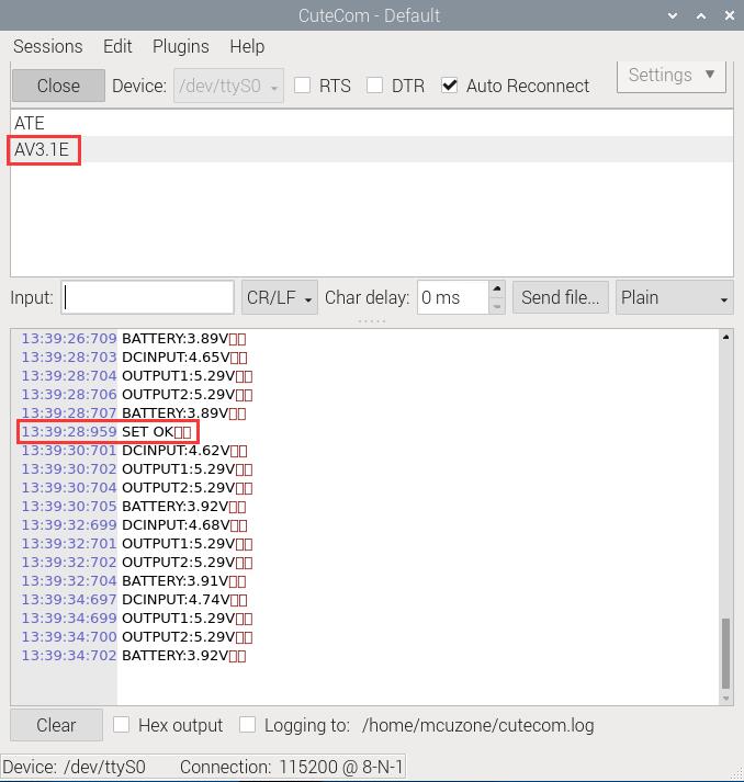
<code>AV3.1E</code> | <code>AV3.1E</code> indicates that the power output will be shut down when the battery voltage drops below 3.1V: | ||
http://www.mcuzone.com/wiki/3002_21700_Power_Supply/3002_21700_Power_Supply_18.jpg | http://www.mcuzone.com/wiki/3002_21700_Power_Supply/3002_21700_Power_Supply_18.jpg | ||
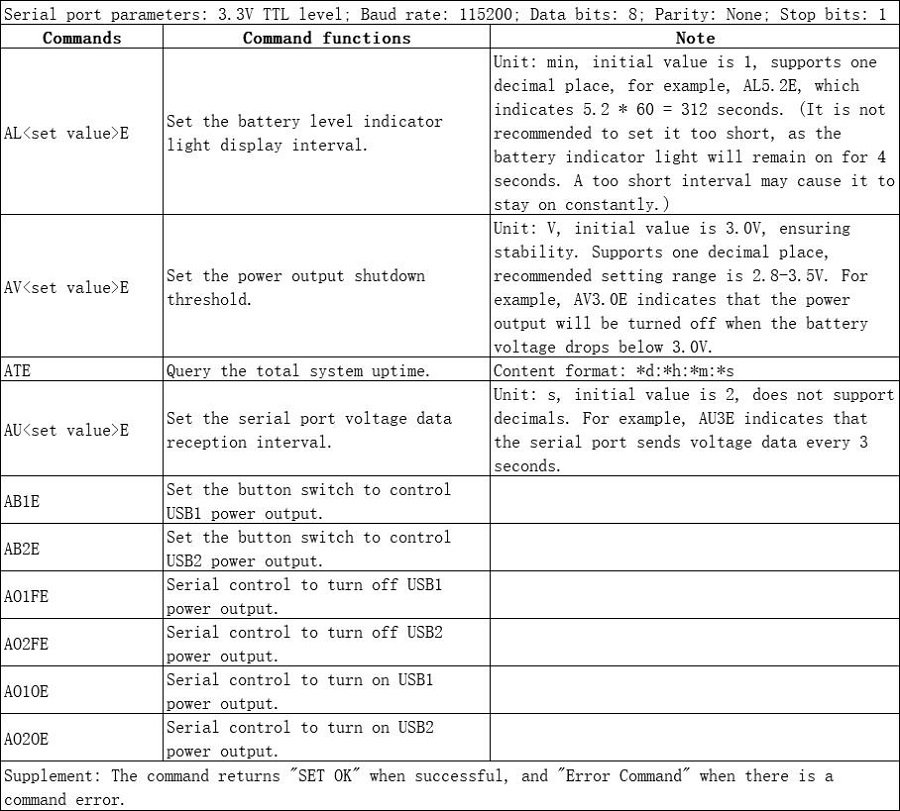
List of common control commands: | |||
http://www.mcuzone.com/wiki/3002_21700_Power_Supply/3002_21700_Power_Supply_37.jpg | |||
== '''IV. Interactive serial port(Ubuntu system)''' == | |||
The version of the Ubuntu system is: ubuntu-24.10-preinstalled-desktop-arm64+raspi.img.xz | |||
== ''' | |||
You can download the Ubuntu system in: | |||
https://ubuntu.com/download/raspberry-pi | https://ubuntu.com/download/raspberry-pi | ||
=== 4.1 | === 4.1 Set configuration === | ||
Modify the configuration of the Ubuntu system: | |||
<code>sudo nano /boot/firmware/cmdline.txt</code> | <code>sudo nano /boot/firmware/cmdline.txt</code> | ||
| 第220行: | 第168行: | ||
http://www.mcuzone.com/wiki/3002_21700_Power_Supply/3002_21700_Power_Supply_20.jpg | http://www.mcuzone.com/wiki/3002_21700_Power_Supply/3002_21700_Power_Supply_20.jpg | ||
Delete the text in the red box, then save and exit: | |||
<code>console=tty1</code> | <code>console=tty1</code> | ||
| 第230行: | 第178行: | ||
http://www.mcuzone.com/wiki/3002_21700_Power_Supply/3002_21700_Power_Supply_22.jpg | http://www.mcuzone.com/wiki/3002_21700_Power_Supply/3002_21700_Power_Supply_22.jpg | ||
Add the text in the red box, then save and exit: | |||
<code>enable_uart=1</code> | <code>enable_uart=1</code> | ||
| 第236行: | 第184行: | ||
http://www.mcuzone.com/wiki/3002_21700_Power_Supply/3002_21700_Power_Supply_23.jpg | http://www.mcuzone.com/wiki/3002_21700_Power_Supply/3002_21700_Power_Supply_23.jpg | ||
After making the changes, restart the system. | |||
=== 4.2 | === 4.2 View real-time power parameters === | ||
Serial communication software such as minicom or CuteCom can be used. The installation commands are as follows: | |||
<code>sudo apt install minicom</code> | <code>sudo apt install minicom</code> | ||
| 第245行: | 第193行: | ||
<code>sudo apt install cutecom</code> | <code>sudo apt install cutecom</code> | ||
Under the Ubuntu system, the interactive serial port is ttyS0 (note that S is uppercase). | |||
==== 4.2.1 | ==== 4.2.1 Use minicom ==== | ||
Open the Ubuntu terminal and run minicom: | |||
<code>sudo minicom -D /dev/ttyS0</code> | <code>sudo minicom -D /dev/ttyS0</code> | ||
You will then see the interactive information: | |||
http://www.mcuzone.com/wiki/3002_21700_Power_Supply/3002_21700_Power_Supply_27.jpg | http://www.mcuzone.com/wiki/3002_21700_Power_Supply/3002_21700_Power_Supply_27.jpg | ||
==== 4.2.2 | ==== 4.2.2 Use CuteCom ==== | ||
Open the Ubuntu terminal and run CuteCom, open the ttyS0 serial port, and view the interaction information in the output window: | |||
<code>sudo cutecom</code> | <code>sudo cutecom</code> | ||
| 第263行: | 第211行: | ||
http://www.mcuzone.com/wiki/3002_21700_Power_Supply/3002_21700_Power_Supply_25.jpg | http://www.mcuzone.com/wiki/3002_21700_Power_Supply/3002_21700_Power_Supply_25.jpg | ||
== ''' | == '''V. Product images''' == | ||
http://www.mcuzone.com/wiki/3002_21700_Power_Supply/3002_21700_Power_Supply_28.jpg | http://www.mcuzone.com/wiki/3002_21700_Power_Supply/3002_21700_Power_Supply_28.jpg | ||
| 第270行: | 第218行: | ||
http://www.mcuzone.com/wiki/3002_21700_Power_Supply/3002_21700_Power_Supply_30.jpg<nowiki/> | http://www.mcuzone.com/wiki/3002_21700_Power_Supply/3002_21700_Power_Supply_30.jpg<nowiki/> | ||
{{ | {{Contact_Us_icon}} | ||
2024年11月22日 (五) 15:45的最新版本
Keywords
Raspberry 4B, Raspberry Pi, 21700 Power Battery, 5V2A, 5V3A, 5V4A, Interactive Serial Port, Serial Port Commands, Charge and Discharge Simultaneously, Real-time Voltage Monitoring
I. Introduction
The 21700 power module is specifically designed for the Raspberry Pi and can supply power to it via pogo pins or a USB port. The board is divided into two areas. On the left side, there is a typical power bank design where charging and discharging share the same port. This means that connecting an external power source will charge the battery, while connecting a device will allow it to be powered externally. The charging capacity can reach up to 2.8A, and the discharging capacity can provide up to 5V2A. The right side of the board features a battery boost circuit with a main power switch. It can supply power to the Raspberry Pi through gold-plated pogo. Additionally, it has two USB-A ports for powering other peripherals. Furthermore, battery information can be viewed via a serial interface. The battery circuit supports simultaneous charging and discharging, and it comes equipped with overcharge protection, overheat protection during charging, as well as overheat protection, overcurrent protection, undervoltage protection, and short-circuit protection during discharging. Practical tests have shown that when connected to a Raspberry Pi 4B playing 1080P video, the battery life can last up to 10 hours using the probe version.
II. Hardware Resources
1. Hardware Features
- Suitable for Raspberry Pi series motherboards, featuring two independently dual output interfaces: one at 5V2A and the other at 5V4A.
- The 5V2A port offers three types of connectors (USB-C, USB-A, micro USB) and supports simultaneous input and output. This means that when 5V is input, it enters charging mode, and when a device is connected, it switches to discharging mode.
- The 5V2A USB-A port supports charging both iPhone and Android devices.
- The 5V4A output provides stable power, functioning as a UPS. It features dual USB high-current ports that share a 4A current and can also supply power via pogo pins.
- One output switch and one output control button are provided to manage the two USB-A ports.
- The board features four LED lights for indicating the battery level.
- A battery level indicator button is provided to check the battery status.
- A power status indicator light.
- The probe version features serial communication pogo pins, while the USB version includes onboard serial communication pins. Both are used for serial communication.
- Two 21700 batteries can be connected in parallel, providing a maximum capacity of 10000mAh. The module can also operate using just one battery.
- Size: 85*56mm; Height: 38.6mm, measured from the bottom acrylic plate to the copper pillars on the board.
- The PCB board uses a gold plating process and is produced without lead. The PCB board has passed UL and ROHS certification, with a fire resistance rating of 94V-0.

2. Product Features
- The MCU is used for power management and supports serial output, which is used to indicate the battery voltage and output voltage.
- Two MOSFETs are used for output control, supporting low-voltage shutdown. They also support manual or serial command control for turning the output on or off.
- Charge head (input) detection function.
3. Serial port output characteristics
- The system automatically reports the battery voltage and output voltage, enabling the host system to estimate the system's runtime and prepare for data protection in advance. The reporting interval can be set via a command, with a default interval of 2 seconds.
- Automatically illuminate the battery level indicator LEDs for easy observation. The illumination interval can be set via a command, with a default of 1 minute.
- The low-voltage protection threshold for the battery can be set, with a default setting of 3V to shut off the output.
- The system can query the total uptime since power-on.
- The system can turn off or turn on the two output channels via commands.
- The system allows setting a button to control either one or both output channels.
- Note: Current sampling is not supported.
The serial cable is used for data transmission and should be connected as shown in the following diagram:

4. Battery Description
This product uses two 21700 lithium-ion power batteries in parallel to provide power, offering long-lasting operation with a reliable discharge capability of over 10A, ensuring sufficient power for dual outputs of 5V2A and 5V4A. Switch-mode charging is used, so even if the charging current reaches 2.8A, neither the chip nor the battery will trigger overheat protection. It is recommended to use an adapter with an output capability of 5V2.5A or higher for charging. If the adapter cannot meet the 2.5A output requirement, it may result in the charger's protection mechanism kicking in (preventing charging) or even cause damage.
Battery polarity and installation instructions:

The 21700 battery has a large energy capacity. Please make sure to carefully check the orientation before inserting it into the battery holder. If inserted incorrectly, there is a risk of smoking, fire, or even explosion. For everyone's safety, please verify carefully before inserting. Do not plug or unplug unless necessary!
We will not be liable for any risks resulting from incorrect battery connection. Please use with caution. Additionally, damage to components caused by incorrect battery connection is not covered under warranty.
Damage caused to the battery or device due to charging with a user-supplied power adapter is not covered under warranty. Please use high-quality, genuine power supplies, or purchase one from our company.
5. Power indication and output control
The remaining battery level can be checked by pressing the battery level detection button:

The output control button can be used to control the output of USB1 or USB2:
6. Dual output application
One of the key features of this product is its support for dual output:
One output is 5V2A, which is always on; it can connect to three external devices simultaneously and also supports simultaneous charging and discharging, meaning one input and two outputs. Whether connecting two or three outputs simultaneously, they all share 5V2A.
One output is a high-power 5V4A output, featuring a pogo pin interface and two USB-A ports. Therefore, if using the probe version, this output port can simultaneously connect to 3 devices, sharing 5V4A.
This product can connect up to six devices simultaneously; if charging and discharging at the same time, it can connect up to five devices simultaneously. It supports the simultaneous operation of a Raspberry Pi, 4G module, servos, radar modules, and more using the same power module, solving power supply issues.

III. Interactive serial port(Raspberry Pi OS)
The version of the Raspberry Pi OS is: 2024-10-22-raspios-bookworm-armhf.img.xz
You can download the Raspberry Pi OS in:
https://www.raspberrypi.com/software/operating-systems/#raspberry-pi-os-64-bit
3.1 Configure Raspberry Pi OS
The Raspberry Pi logo in the upper left corner — Preferences — Raspberry Pi Configuration — Interfaces
Enable "Serial Port", disable "Serial Console", as shown in the figure:
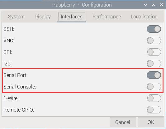
This completes the serial port configuration.
3.2 View real-time power parameters
Use serial commands for interaction, serial communication software such as minicom or CuteCom can be used. The installation commands are as follows:
sudo apt install minicom
sudo apt install cutecom
Under the Raspberry Pi OS, the interactive serial port is ttyS0 (note that S is uppercase).
3.2.1 Use minicom
Open the Raspberry Pi terminal and run minicom:
sudo minicom -D /dev/ttyS0
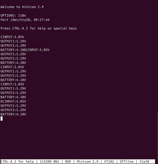
You will then see the interactive information:
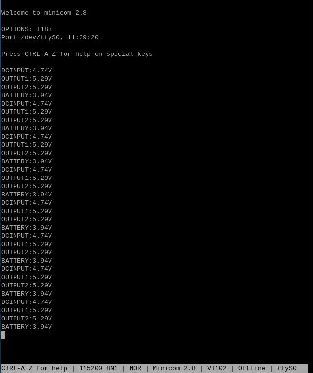
DCINPUT: DC input voltage
OUTPUT1: Output voltage 1
OUTPUT2: Output voltage 2
BATTERY: Battery voltage
3.2.2 Use CuteCom
Run the CuteCom, open the ttyS0 serial port, and view the interaction information in the output window:
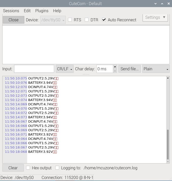
3.3 Run the power system control commands
Run the CuteCom, open the ttyS0 serial port, enter commands in the Input window, and view the corresponding return information in the Output window.
For example, ATE indicates that query the total system uptime:
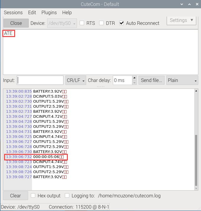
AV3.1E indicates that the power output will be shut down when the battery voltage drops below 3.1V:
List of common control commands:
IV. Interactive serial port(Ubuntu system)
The version of the Ubuntu system is: ubuntu-24.10-preinstalled-desktop-arm64+raspi.img.xz
You can download the Ubuntu system in:
https://ubuntu.com/download/raspberry-pi
4.1 Set configuration
Modify the configuration of the Ubuntu system:
sudo nano /boot/firmware/cmdline.txt

Delete the text in the red box, then save and exit:
console=tty1

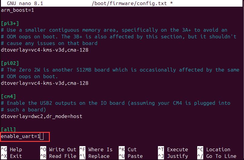
sudo nano /boot/firmware/config.txt

Add the text in the red box, then save and exit:
enable_uart=1
After making the changes, restart the system.
4.2 View real-time power parameters
Serial communication software such as minicom or CuteCom can be used. The installation commands are as follows:
sudo apt install minicom
sudo apt install cutecom
Under the Ubuntu system, the interactive serial port is ttyS0 (note that S is uppercase).
4.2.1 Use minicom
Open the Ubuntu terminal and run minicom:
sudo minicom -D /dev/ttyS0
You will then see the interactive information:
4.2.2 Use CuteCom
Open the Ubuntu terminal and run CuteCom, open the ttyS0 serial port, and view the interaction information in the output window:
sudo cutecom
V. Product images


Contact Us
Email: mcuzone@vip.qq.com
Tel: +86(0)13957118045
If there are any omissions, errors, or infringements on this page, please contact us through the above methods. Thank you!
Copyright 2004-2024 Wildchip


 QQ:8204136