1006 RPi0 4G MiniPCIe(Expand 4G Module via MiniPCIe):修订间差异
| (未显示2个用户的54个中间版本) | |||
| 第1行: | 第1行: | ||
[[1006 RPi0 4G MiniPCIe(MiniPCIe扩展4G模组)|切换语言为中文]] | |||
== '''Keywords''' == | == '''Keywords''' == | ||
Raspberry Pi, | Raspberry Pi Zero, Zero W, Zero WH, Zero 2W, miniPCIe Cat4 4G LTE, USB2.0-A, Ethernet, Expansion Board, SSH | ||
== '''I. Introduction''' == | == '''I. Introduction''' == | ||
This expansion board is based on the Raspberry Pi Zero series boards and extends MiniPCIe 4G functionality. It utilizes the gold-plated test points for USB and power on the back of the Raspberry Pi Zero board for peripheral expansion. This expansion board essentially acts as a USB HUB, connecting the expansion board to the Zero's USB port via pogo pins, eliminating the need for external USB cables, saving space, and enhancing aesthetics. It expands to four USB ports via USB, including one USB-to-100Mbps wired Ethernet, one USB connected to a MiniPCIe 4G Cat4 module, and two USB2.0-A host interfaces. | |||
The expansion board supports Raspberry Pi Zero, Zero W, Zero WH, and Zero 2W, as well as the Orange Pi Zero 2W. | |||
The 4G LTE module is a high-cost-performance module aimed at medium-speed IoT applications, capable of meeting the majority of connectivity and transmission needs. The multiple 4G LTE modules we provide are driver-free on the Raspberry Pi OS, Ubuntu OS and OpenWrt OS, meaning they are automatically recognized without the need for you to install additional drivers. Similarly, on the Ubuntu system for the Orange Pi, the 4G modules are also driver-free. The 4G LTE module supports Qualcomm 4G/GPS, NL668-EU/EAU/AM and EG25-G. | |||
'''''Choosing a 4G module requires that the Bands of the local SIM card operator match those of the 4G module. If the Bands do not match, the system can recognize the 4G model but will not be able to connect to the internet. Therefore, please choose carefully before purchasing.''''' | |||
== '''II. Hardware Spec''' == | == '''II. Hardware Spec''' == | ||
1. Four gold-plated pogo pins are used separately for powering the expansion board and for USB communication. | |||
2. | 2. One USB-C power supply, or you can power it from the Raspberry Pi's own micro port(choose one of the two options), and the Raspberry Pi's micro USB port should not be connected to any other devices. | ||
3. One USB2.0 MiniPCIe interface is used for connecting the 4G LTE module. | |||
4. One Nano SIM card slot. | |||
5. One 100Mbps Ethernet port. | |||
6. Two USB2.0-A ports, each capable of ensuring a 2A current output. | |||
7. Three LED indicators: PWR/MODE/ACT LED. | |||
8. Onboard reset button for 4G module. | |||
9. Size: 85*70mm. | |||
10. The PCB board uses an ENIG process, is lead-free, and the material has passed UL and RoHS certification with a fire resistance rating of 94V-0. | |||
11. An optional aluminum alloy enclosure is available. | |||
Note 1: After connecting this expansion board, the Micro USB port on the Zero will no longer be usable. | Note 1: After connecting this expansion board, the Micro USB port on the Zero will no longer be usable. | ||
| 第34行: | 第40行: | ||
Note 2: In some systems, it is necessary to disable the OTG function and set the USB mode to Host mode. | Note 2: In some systems, it is necessary to disable the OTG function and set the USB mode to Host mode. | ||
http://www.mcuzone.com/wiki/1006_RPi0_4G_MiniPCIe/1006_RPi0_4G_MiniPCIe_66.jpg | |||
http://www.mcuzone.com/wiki/1006_RPi0_4G_MiniPCIe/ | http://www.mcuzone.com/wiki/1006_RPi0_4G_MiniPCIe/1006_RPi0_4G_MiniPCIe_51.jpg | ||
http://www.mcuzone.com/wiki/1006_RPi0_4G_MiniPCIe/ | http://www.mcuzone.com/wiki/1006_RPi0_4G_MiniPCIe/1006_RPi0_4G_MiniPCIe_57.jpg | ||
http://www.mcuzone.com/wiki/1006_RPi0_4G_MiniPCIe/1006_RPi0_4G_MiniPCIe_54.jpg | |||
== | == '''III. Work with Raspberry Pi OS''' == | ||
This document uses the Raspberry Pi OS and OpenWrt system for testing. | This document uses the Raspberry Pi OS and OpenWrt system for testing. | ||
| 第55行: | 第61行: | ||
The version of the OpenWrt is: openwrt-bcm27xx-bcm2709-rpi-2-squashfs-sysupgrade-linux-6.1.98-20240723.img.gz | The version of the OpenWrt is: openwrt-bcm27xx-bcm2709-rpi-2-squashfs-sysupgrade-linux-6.1.98-20240723.img.gz | ||
=== 3 | === 3.1 View hardware devices === | ||
==== 3.1.1 View USB devices ==== | |||
==== 3 | |||
Open the terminal in Raspberry Pi OS and enter the command<code>lsusb</code>, as shown in the image below: | Open the terminal in Raspberry Pi OS and enter the command<code>lsusb</code>, as shown in the image below: | ||
| 第135行: | 第94行: | ||
http://www.mcuzone.com/wiki/0007_Zero_4G_Cat1/0007_Zero_4G_Cat1_57.jpg | http://www.mcuzone.com/wiki/0007_Zero_4G_Cat1/0007_Zero_4G_Cat1_57.jpg | ||
==== | ==== 3.1.2 View network devices ==== | ||
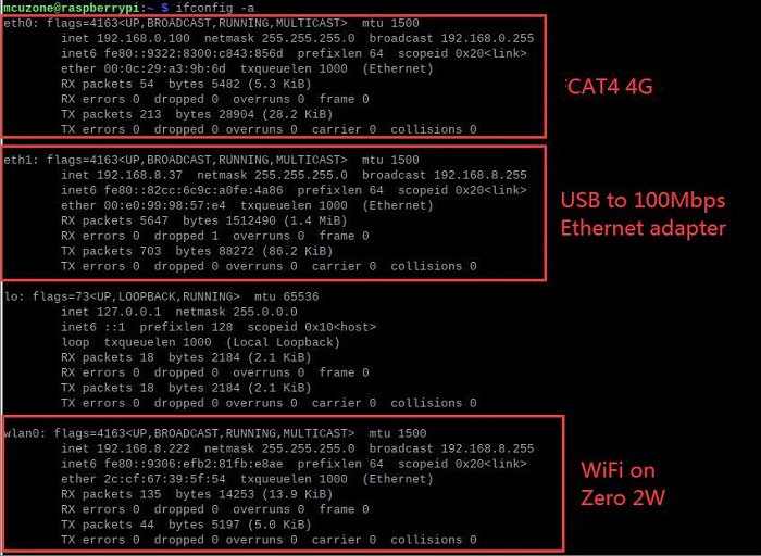
Open the terminal in Raspberry Pi OS and enter the command <code>ifconfig -a</code>, as shown in the image below: | Open the terminal in Raspberry Pi OS and enter the command <code>ifconfig -a</code>, (Our internal IP is 192.168.8.x, used to determine the expansion board's 100 Mbps network card device.) as shown in the image below: | ||
'''CAT4 4G:''' | |||
http://www.mcuzone.com/wiki/1006_RPi0_4G_MiniPCIe/1006_RPi0_4G_MiniPCIe_42.jpg | |||
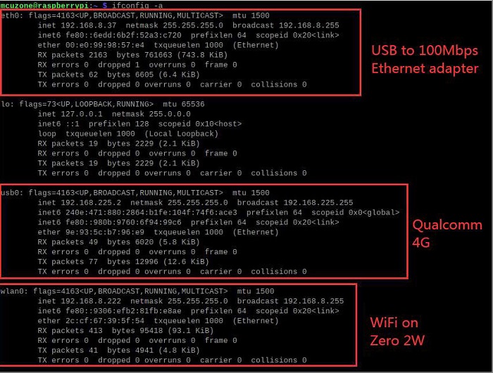
'''Qualcomm 4G/GPS,NL668-EU/EAU/AM:''' | |||
http://www.mcuzone.com/wiki/1006_RPi0_4G_MiniPCIe/ | http://www.mcuzone.com/wiki/1006_RPi0_4G_MiniPCIe/1006_RPi0_4G_MiniPCIe_43.jpg | ||
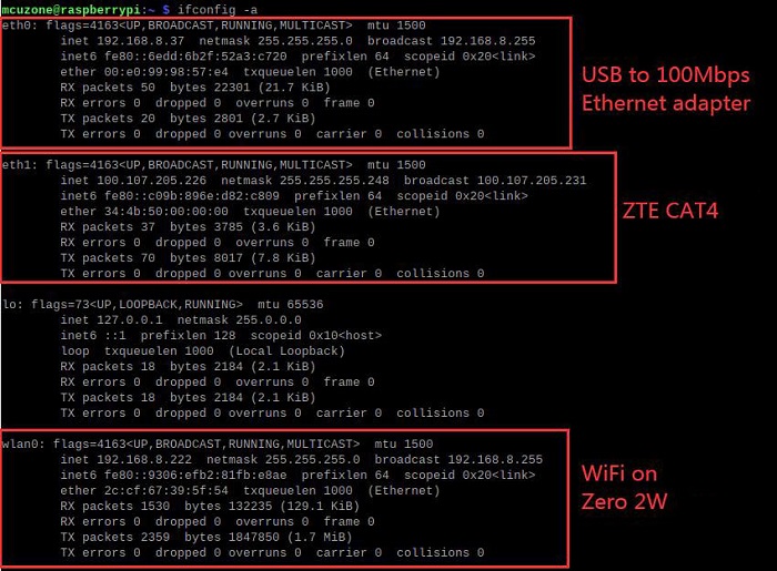
'''ZTE CAT4:''' | |||
http://www.mcuzone.com/wiki/1006_RPi0_4G_MiniPCIe/1006_RPi0_4G_MiniPCIe_46.jpg | |||
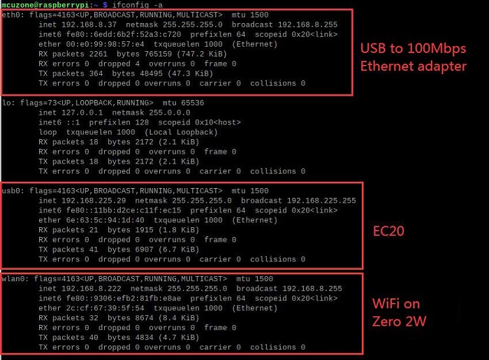
'''EG25-G:''' | |||
http://www.mcuzone.com/wiki/1006_RPi0_4G_MiniPCIe/1006_RPi0_4G_MiniPCIe_44.jpg | |||
=== | === 3.2 Test network devices === | ||
This section uses a Qualcomm 4G module as the test module. The same as NL668-EU/EAU/AM. | |||
==== | ==== 3.2.1 Ping tests ==== | ||
When testing, there is a priority order. If there are specific requirements for internal and external networks, please adjust the metric values of each network and the DNS server settings. | When testing, there is a priority order. If there are specific requirements for internal and external networks, please adjust the metric values of each network and the DNS server settings. | ||
For related settings regarding network card priority, please refer to the following link: | |||
[[1001 RPi0 4G Cat1-ETH(100M ETH 4G Cat1 USB2.0-A RS485 version optional)#4.2.2 Set network adapter priority|1. Set network adapter priority]] | |||
[[1001 RPi0 4G Cat1-ETH(100M ETH 4G Cat1 USB2.0-A RS485 version optional)#4.2.3 Using udhcpc to specify DNS servers|2. Using udhcpc to specify DNS servers]] | |||
[[1001 RPi0 4G Cat1-ETH(100M ETH 4G Cat1 USB2.0-A RS485 version optional)#4.2.4 Examples of how to use udhcpc|3. Examples of how to use udhcpc]] | |||
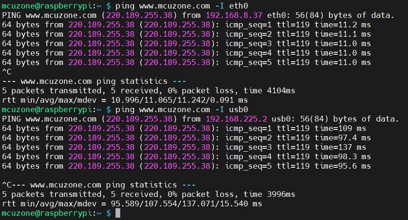
Now the system is connected to both a wired Gigabit network card and 4G, you can use the -I parameter to specify which network interface to start pinging from, as shown below: | |||
<code>ping www.mcuzone.com -I eth0</code> | <code>ping www.mcuzone.com -I eth0</code> | ||
<code>ping www.mcuzone.com -I | <code>ping www.mcuzone.com -I usb0</code> | ||
http://www.mcuzone.com/wiki/1006_RPi0_4G_MiniPCIe/ | http://www.mcuzone.com/wiki/1006_RPi0_4G_MiniPCIe/1006_RPi0_4G_MiniPCIe_59.jpg | ||
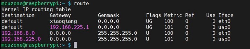
Priority can be checked by executing the <code>route</code> command; the network card with the smaller metric value will be preferred for communication. | Priority can be checked by executing the <code>route</code> command; the network card with the smaller metric value will be preferred for communication. | ||
http://www.mcuzone.com/wiki/1006_RPi0_4G_MiniPCIe/ | http://www.mcuzone.com/wiki/1006_RPi0_4G_MiniPCIe/1006_RPi0_4G_MiniPCIe_60.jpg | ||
We can also force communication through another network by disabling a specific network card. For example, to disable usb0, you can execute the following command: | We can also force communication through another network by disabling a specific network card. For example, to disable usb0, you can execute the following command: | ||
| 第174行: | 第147行: | ||
<code>sudo ifconfig usb0 up</code> | <code>sudo ifconfig usb0 up</code> | ||
==== | ==== 3.2.2 Test speed by iperf3 ==== | ||
You can download iperf3 (Windows version) in: | You can download iperf3 (Windows version) in: | ||
| 第204行: | 第168行: | ||
'''''Note: The USB to 100M Ethernet adapter may not reach full speed due to the performance limitations of the Zero 2W, the USB hub, and the bandwidth usage of the 4G Cat4.''''' | '''''Note: The USB to 100M Ethernet adapter may not reach full speed due to the performance limitations of the Zero 2W, the USB hub, and the bandwidth usage of the 4G Cat4.''''' | ||
=== | ==== 3.2.3 4G network testing ==== | ||
Due to the performance limitations of Zero 2W, running browsers like Chromium for web page speed testing can make the system run very slowly. So we use the lightweight browser surf for speed testing. | |||
Install the lightweight browser surf: | |||
<code>sudo apt install surf</code> | |||
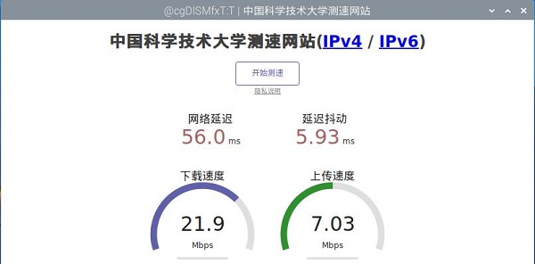
Then turn off WiFi, unplug the Ethernet cable, leaving only the 4G network connection, and go to https://test.ustc.edu.cn/ for speed testing. Execute the following command in the Raspberry Pi terminal: | |||
<code>surf <nowiki>https://test.ustc.edu.cn</nowiki></code> | |||
The results are as follows: | |||
http://www.mcuzone.com/wiki/1006_RPi0_4G_MiniPCIe/1006_RPi0_4G_MiniPCIe_47.jpg | |||
'''''Note: Network speed test results are affected by the network environment and testing methods. The actual speeds may vary; this test is for reference only.''''' | |||
=== 3.3 AT Command for 4G === | |||
==== 3.3.1 Open AT Command serial port ==== | |||
To operate 4G Module using AT commands on a Raspberry Pi, you first need to open the AT command serial port. The method to open it is as follows:(here use Qualcomm 4G for the demonstration) | |||
To open ttyUSB serial port, input the following command: <code>lsusb</code>: | |||
http://www.mcuzone.com/wiki/1006_RPi0_4G_MiniPCIe/1006_RPi0_4G_MiniPCIe_08.jpg | http://www.mcuzone.com/wiki/1006_RPi0_4G_MiniPCIe/1006_RPi0_4G_MiniPCIe_08.jpg | ||
| 第245行: | 第226行: | ||
http://www.mcuzone.com/wiki/1006_RPi0_4G_MiniPCIe/1006_RPi0_4G_MiniPCIe_13.jpg | http://www.mcuzone.com/wiki/1006_RPi0_4G_MiniPCIe/1006_RPi0_4G_MiniPCIe_13.jpg | ||
Note: The | '''''Note: The operation procedures are the same, but for different 4G models, the corresponding USB IDs will vary, so please refer to the actual USB ID using the <code>lsusb</code> command.''''' | ||
==== | ==== 3.3.2 Common AT commands ==== | ||
1) Check if the SIM card is detected: | 1) Check if the SIM card is detected: | ||
| 第286行: | 第267行: | ||
The two commands mentioned above can be used in pairs to allow the module to re-register with the network without restarting the 4G module. | The two commands mentioned above can be used in pairs to allow the module to re-register with the network without restarting the 4G module. | ||
== ''' | === 3.4 Modify the IP address of the 4G === | ||
'''1) Qualcomm 4G/GPS,NL668-EU/EAU/AM, ZTE CAT4:''' | |||
Set the 4G module's IP to directly obtain a public IP. Please execute the AT command: | |||
= | Set the IP to public: <code>AT+GTIPPASS=1</code> | ||
http://www.mcuzone.com/wiki/ | Set the IP to private: <code>AT+GTIPPASS=0</code> | ||
Check whether the current IP is a public or private IP:<code>AT+GTIPPASS?</code> | |||
'''2) CAT4 4G:''' | |||
Execute the AT command: | |||
<code>AT+ROUTEIP=<newip></code> | |||
Note: only addresses in the format of 192.168.x.1 are supported. If you set <code>AT+ROUTEIP=192.168.3.1</code>, the final IP address obtained will be 192.168.3.100. After making the changes, you need to power off and restart the system. | |||
Query current IP: <code>AT+ROUTEIP?</code>, it returns two values, the first one is the old IP, and the second one is the new IP. | |||
Test command: <code>AT+ROUTEIP=?</code> | |||
=== 3.5 GPS Testing === | |||
==== 3.5.1 Qualcomm 4G-GPS and NL668-EU/EAU/AM ==== | |||
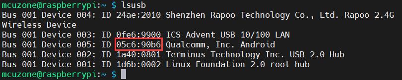
Execute the command <code>lsusb</code>, as shown in the figure below: | |||
http://www.mcuzone.com/wiki/0024_MP4GUSB/0024_MP4GUSB_04.jpg | |||
Note down the ID of the 4G module: 05c6 90b6. | |||
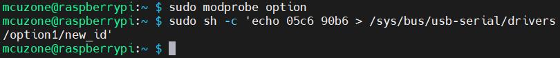
Use the following command to open the ttyUSB serial port, where the value following echo is the ID value recorded above: | |||
<code>sudo modprobe option</code> | |||
<code>sudo sh -c 'echo 05c6 90b6 > /sys/bus/usb-serial/drivers/option1/new_id'</code> | |||
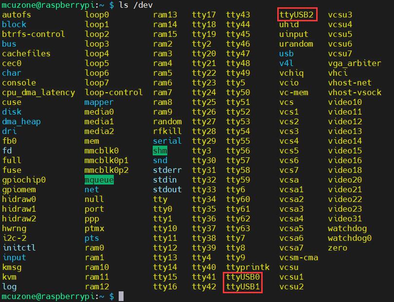
After executing the two commands above, the system should have three additional devices: ttyUSB0/1/2. You can check them by executing <code>ls /dev</code>: | |||
http://www.mcuzone.com/wiki/0024_MP4GUSB/0024_MP4GUSB_06.jpg | |||
Execute minicom and open the ttyUSB0 serial port: | |||
<code>sudo minicom -D /dev/ttyUSB0</code> | |||
Then execute: | |||
<code>at+gtgpsepo=1</code> //Enable AGPS | |||
<code>at+gtgpspower=1</code> //Enable GPS | |||
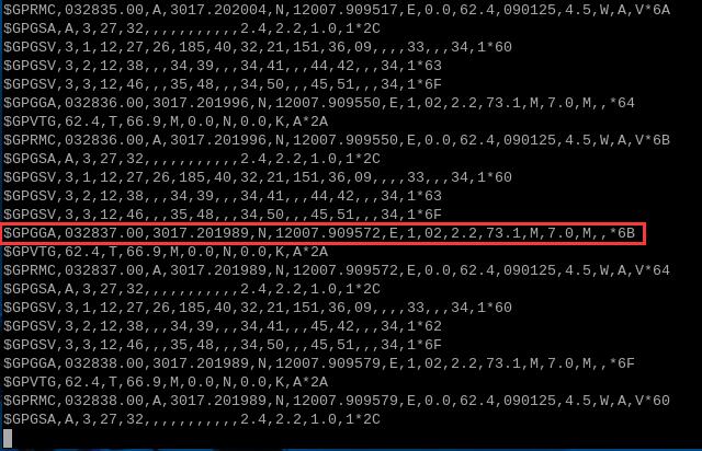
Wait a moment for the positioning to succeed, then execute: | |||
<code>at+gtgps?</code> //View NMEA information | |||
You can then see that the serial port outputs GPS information: | |||
http://www.mcuzone.com/wiki/0012_MPUUART_MP4232/0012_MPUUART_MP4232_70.jpg | |||
==== 3.5.2 EG25-GPS ==== | |||
Execute the command <code>lsusb</code>, as shown in the figure below: | |||
http://www.mcuzone.com/wiki/5002_CM5_Basic/5002_CM5_Basic_62.jpg | |||
Note down the ID of the 4G module: 2c7c 0125. | |||
Use the following command to open the ttyUSB serial port, where the value following echo is the ID value recorded above: | |||
<code>sudo modprobe option</code> | |||
<code>sudo sh -c 'echo 2c7c 0125 > /sys/bus/usb-serial/drivers/option1/new_id'</code> | |||
After executing the two commands above, the system should have three additional devices: ttyUSB0/1/2/3. You can check them by executing <code>ls /dev/ttyUSB*</code>: | |||
http://www.mcuzone.com/wiki/5002_CM5_Basic/5002_CM5_Basic_63.jpg | |||
Execute minicom and open the ttyUSB3 serial port: | |||
<code>sudo minicom -D /dev/ttyUSB3</code> | |||
Then execute: | |||
<code>AT+QGPS=1</code> //Open GPS | |||
After executing successfully, open ttyUSB1: | |||
<code>sudo minicom -D /dev/ttyUSB1</code> | |||
You can then see that the serial port outputs GPS information; wait a moment for it to get a fix: | |||
http://www.mcuzone.com/wiki/5002_CM5_Basic/5002_CM5_Basic_64.jpg | |||
== '''IV. Work with OpenWrt''' == | |||
We are using the Raspberry Pi Zero 2W with CAT4 4G to demonstrate running OpenWrt, can be configured as a one-in-one-out switch mode. The 4G module on the expansion board can serve as the WAN port (for direct 4G internet access), while the Ethernet port is configured as the LAN port for connecting to a PC. | |||
The OpenWrt which be used in this document is: openwrt-bcm27xx-bcm2709-rpi-2-squashfs-sysupgrade-linux-6.1.98-20240723.img.gz | |||
=== 4.1 Configure the system === | |||
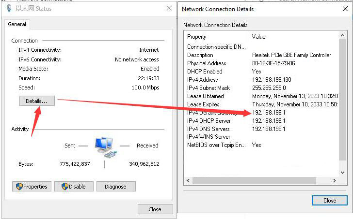
Connect the Ethernet port of the expansion board to the PC's Ethernet port using an Ethernet cable. The 4G module requires a mobile SIM card to be inserted. Power on and start the system. We find Network and Internet settings in Windows, then open the connected network under Ethernet to view the default gateway IP address. This address is the backend configuration page address for the OpenWrt system. As shown in the figure, the address for this test is 192.168.198.1: | |||
http://www.mcuzone.com/wiki/1006_RPi0_4G_MiniPCIe/1006_RPi0_4G_MiniPCIe_14.jpg | |||
http://www.mcuzone.com/wiki/1006_RPi0_4G_MiniPCIe/ | Then open a web browser and enter 192.168.198.1 to access the OpenWrt system. The default username is <code>root</code>, and the default password is <code>password</code>: | ||
http://www.mcuzone.com/wiki/1006_RPi0_4G_MiniPCIe/1006_RPi0_4G_MiniPCIe_15.jpg | |||
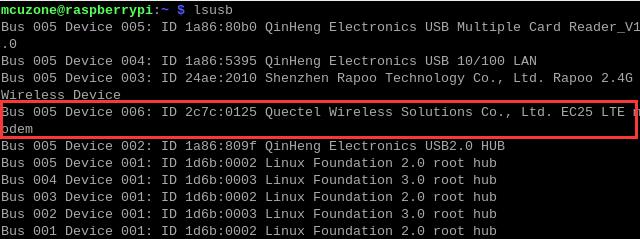
After logging into the OpenWrt system, click on "System - TTYD Terminal," then run <code>lsusb</code> to check if the 4G module is recognized. The red box in the image below indicates that the CAT4 4G module has been recognized. | |||
http://www.mcuzone.com/wiki/1006_RPi0_4G_MiniPCIe/ | http://www.mcuzone.com/wiki/1006_RPi0_4G_MiniPCIe/1006_RPi0_4G_MiniPCIe_33.jpg | ||
Execute the command <code>ip addr</code> to view all network devices. In the figure below, the No. 6, <code>eth1</code> represents the network name of the CAT4 4G module. If you use NL668-AM/EU/EAU/Qualcomm 4G, this network name could be <code>usb0</code>. Please refer to the actual situation: | |||
http://www.mcuzone.com/wiki/1006_RPi0_4G_MiniPCIe/ | http://www.mcuzone.com/wiki/1006_RPi0_4G_MiniPCIe/1006_RPi0_4G_MiniPCIe_49.jpg | ||
=== | === 4.2 ADD the 4G module === | ||
Click on "Network - Interfaces," and then click on "ADD NEW INTERFACE...". | |||
http://www.mcuzone.com/wiki/1006_RPi0_4G_MiniPCIe/1006_RPi0_4G_MiniPCIe_16.jpg | http://www.mcuzone.com/wiki/1006_RPi0_4G_MiniPCIe/1006_RPi0_4G_MiniPCIe_16.jpg | ||
Set it up according to the following picture: | |||
http://www.mcuzone.com/wiki/1006_RPi0_4G_MiniPCIe/1006_RPi0_4G_MiniPCIe_21.jpg | http://www.mcuzone.com/wiki/1006_RPi0_4G_MiniPCIe/1006_RPi0_4G_MiniPCIe_21.jpg | ||
If 4G is NL668-AM/EU/EAU/Qualcomm 4G, Set it up as follows:http://www.mcuzone.com/wiki/1006_RPi0_4G_MiniPCIe/1006_RPi0_4G_MiniPCIe_17.jpg | |||
In the "Firewall Settings", select the WAN and then click the "SAVE & APPLY" button: | |||
http://www.mcuzone.com/wiki/1006_RPi0_4G_MiniPCIe/1006_RPi0_4G_MiniPCIe_18.jpg | http://www.mcuzone.com/wiki/1006_RPi0_4G_MiniPCIe/1006_RPi0_4G_MiniPCIe_18.jpg | ||
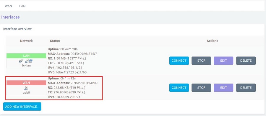
Go back to "Network - Interfaces", wait a moment, and you will see the newly created WAN interface has obtained an IP address. This way, the PC can access the internet through the 4G LTE module(in the two figures below, they are eth1 and usb0 respectively): | |||
http://www.mcuzone.com/wiki/1006_RPi0_4G_MiniPCIe/1006_RPi0_4G_MiniPCIe_22.jpg | http://www.mcuzone.com/wiki/1006_RPi0_4G_MiniPCIe/1006_RPi0_4G_MiniPCIe_22.jpg | ||
http://www.mcuzone.com/wiki/1006_RPi0_4G_MiniPCIe/1006_RPi0_4G_MiniPCIe_19.jpg | |||
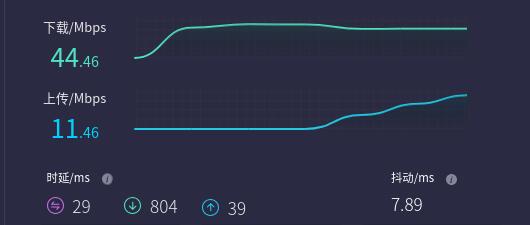
Open https://www.speedtest.cn/ on the PC to test speed. At this point, the PC can access the internet through the 4G LTE module, and the test results are as follows(CAT4 4G): | |||
http://www.mcuzone.com/wiki/1006_RPi0_4G_MiniPCIe/1006_RPi0_4G_MiniPCIe_23.jpg | http://www.mcuzone.com/wiki/1006_RPi0_4G_MiniPCIe/1006_RPi0_4G_MiniPCIe_23.jpg | ||
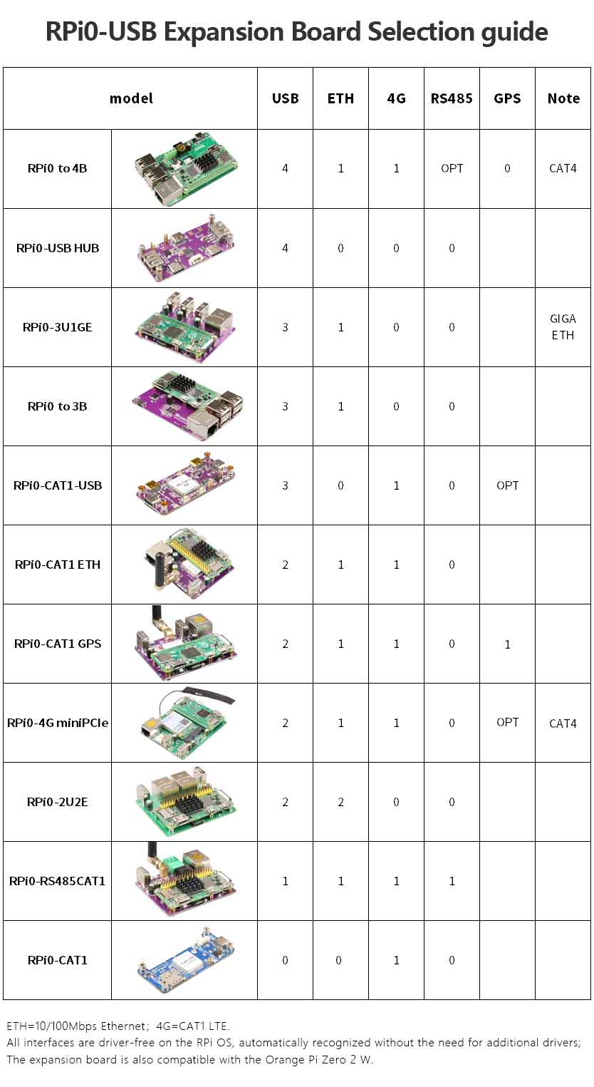
{{ | == '''V. Expansion board selection guide''' == | ||
http://www.mcuzone.com/wiki/1006_RPi0_4G_MiniPCIe/1006_RPi0_4G_MiniPCIe_65.jpg | |||
{{Contact_Us_icon}} | |||
[http://wiki.mcuzone.com/index.php?title=1006_RPi0_4G_MiniPCIe(Expand_4G_Module_via_MiniPCIe) T] | |||
2025年1月16日 (四) 10:47的最新版本
Keywords
Raspberry Pi Zero, Zero W, Zero WH, Zero 2W, miniPCIe Cat4 4G LTE, USB2.0-A, Ethernet, Expansion Board, SSH
I. Introduction
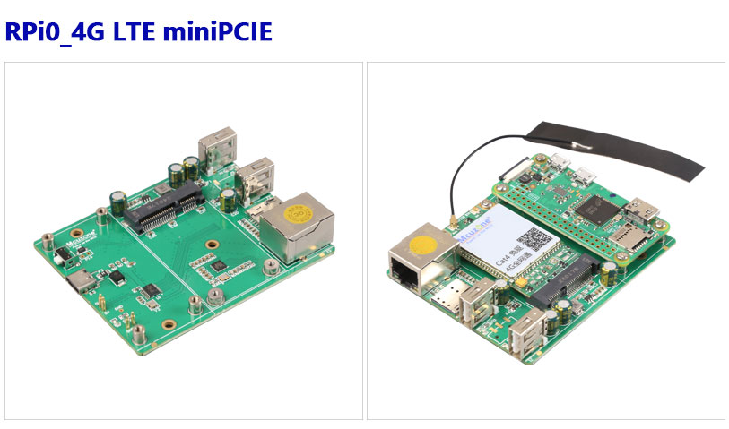
This expansion board is based on the Raspberry Pi Zero series boards and extends MiniPCIe 4G functionality. It utilizes the gold-plated test points for USB and power on the back of the Raspberry Pi Zero board for peripheral expansion. This expansion board essentially acts as a USB HUB, connecting the expansion board to the Zero's USB port via pogo pins, eliminating the need for external USB cables, saving space, and enhancing aesthetics. It expands to four USB ports via USB, including one USB-to-100Mbps wired Ethernet, one USB connected to a MiniPCIe 4G Cat4 module, and two USB2.0-A host interfaces.
The expansion board supports Raspberry Pi Zero, Zero W, Zero WH, and Zero 2W, as well as the Orange Pi Zero 2W.
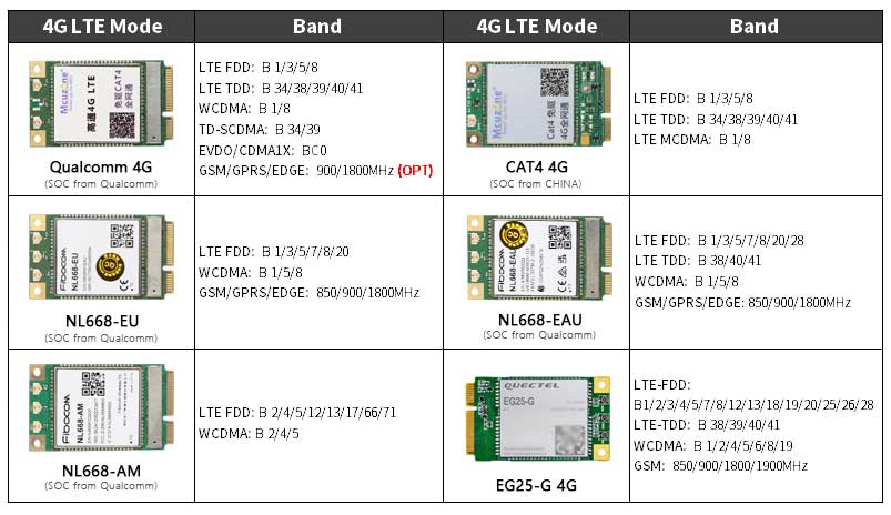
The 4G LTE module is a high-cost-performance module aimed at medium-speed IoT applications, capable of meeting the majority of connectivity and transmission needs. The multiple 4G LTE modules we provide are driver-free on the Raspberry Pi OS, Ubuntu OS and OpenWrt OS, meaning they are automatically recognized without the need for you to install additional drivers. Similarly, on the Ubuntu system for the Orange Pi, the 4G modules are also driver-free. The 4G LTE module supports Qualcomm 4G/GPS, NL668-EU/EAU/AM and EG25-G.
Choosing a 4G module requires that the Bands of the local SIM card operator match those of the 4G module. If the Bands do not match, the system can recognize the 4G model but will not be able to connect to the internet. Therefore, please choose carefully before purchasing.
II. Hardware Spec
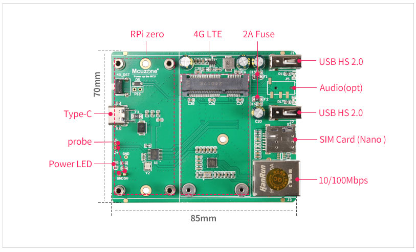
1. Four gold-plated pogo pins are used separately for powering the expansion board and for USB communication.
2. One USB-C power supply, or you can power it from the Raspberry Pi's own micro port(choose one of the two options), and the Raspberry Pi's micro USB port should not be connected to any other devices.
3. One USB2.0 MiniPCIe interface is used for connecting the 4G LTE module.
4. One Nano SIM card slot.
5. One 100Mbps Ethernet port.
6. Two USB2.0-A ports, each capable of ensuring a 2A current output.
7. Three LED indicators: PWR/MODE/ACT LED.
8. Onboard reset button for 4G module.
9. Size: 85*70mm.
10. The PCB board uses an ENIG process, is lead-free, and the material has passed UL and RoHS certification with a fire resistance rating of 94V-0.
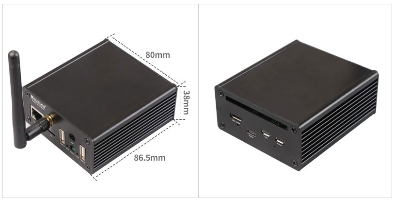
11. An optional aluminum alloy enclosure is available.
Note 1: After connecting this expansion board, the Micro USB port on the Zero will no longer be usable.
Note 2: In some systems, it is necessary to disable the OTG function and set the USB mode to Host mode.
III. Work with Raspberry Pi OS
This document uses the Raspberry Pi OS and OpenWrt system for testing.
The version of the Raspberry Pi OS is: 2024-07-04-raspios-bookworm-arm64.img.xz
You can download the Raspberry Pi OS in:
https://www.raspberrypi.com/software/operating-systems/#raspberry-pi-os-64-bit
(If using the first-generation Raspberry Pi Zero board, which only supports 32-bit systems, please pay attention to the version you download.)
The version of the OpenWrt is: openwrt-bcm27xx-bcm2709-rpi-2-squashfs-sysupgrade-linux-6.1.98-20240723.img.gz
3.1 View hardware devices
3.1.1 View USB devices
Open the terminal in Raspberry Pi OS and enter the commandlsusb, as shown in the image below:
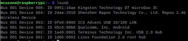
Device 002:External USB Hub;
Device 003:USB to 100Mbps Ethernet adapter;
Device 004:USB2.0-A Interface;
Device 005:4G module;
Device 006:USB2.0-A Interface;
If the system stop at the Raspberry Pi logo and fails to boot:
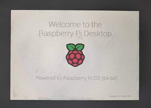
or if after booting, the keyboard, mouse, and 4G module cannot be used, please carefully check whether the pogo pins are aligned with the gold-plated contacts. Additionally, on the PC, open the config.txt file located in the root directory of the TF card to check the USB initialization script:
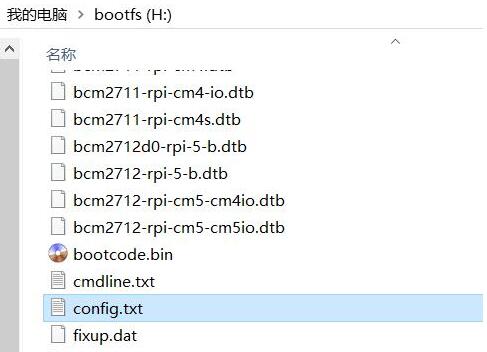
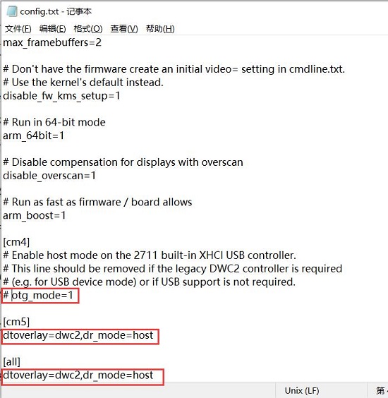
You need to confirm that the three red-boxed areas in the following image are all configured completely. If not, please manually add the missing parts and save the file:
# otg_mode=1 (It is recommended to comment out as follow)
dtoverlay=dwc2,dr_mode=host (These two areas must be ensured to be included.)
3.1.2 View network devices
Open the terminal in Raspberry Pi OS and enter the command ifconfig -a, (Our internal IP is 192.168.8.x, used to determine the expansion board's 100 Mbps network card device.) as shown in the image below:
CAT4 4G:
Qualcomm 4G/GPS,NL668-EU/EAU/AM:
ZTE CAT4:
EG25-G:
3.2 Test network devices
This section uses a Qualcomm 4G module as the test module. The same as NL668-EU/EAU/AM.
3.2.1 Ping tests
When testing, there is a priority order. If there are specific requirements for internal and external networks, please adjust the metric values of each network and the DNS server settings.
For related settings regarding network card priority, please refer to the following link:
1. Set network adapter priority
2. Using udhcpc to specify DNS servers
3. Examples of how to use udhcpc
Now the system is connected to both a wired Gigabit network card and 4G, you can use the -I parameter to specify which network interface to start pinging from, as shown below:
ping www.mcuzone.com -I eth0
ping www.mcuzone.com -I usb0
Priority can be checked by executing the route command; the network card with the smaller metric value will be preferred for communication.
We can also force communication through another network by disabling a specific network card. For example, to disable usb0, you can execute the following command:
sudo ifconfig usb0 down
And enable usb0 by the following command:
sudo ifconfig usb0 up
3.2.2 Test speed by iperf3
You can download iperf3 (Windows version) in:
http://www.mcuzone.com/down/Software.asp?ID=10000634
Install iperf3 (Linux version) by using the following command:
sudo apt-get install iperf3
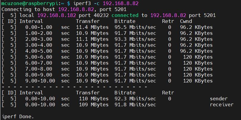
100M Ethernet speed test results:
It is about 92.3Mbps in client mode:
It is about 94.8Mbps in server mode:
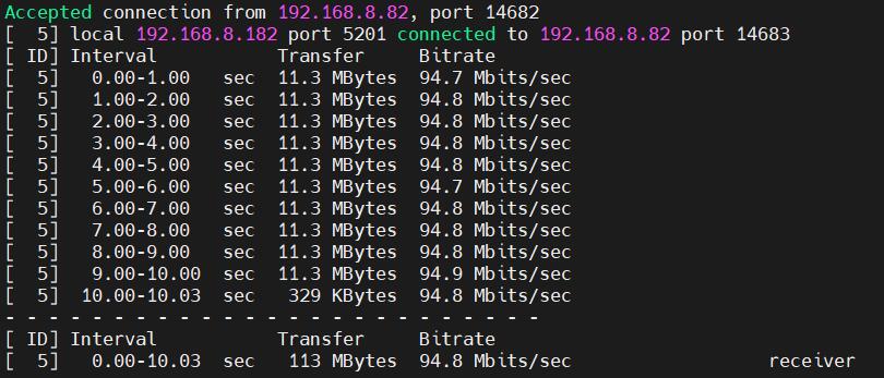
Note: The USB to 100M Ethernet adapter may not reach full speed due to the performance limitations of the Zero 2W, the USB hub, and the bandwidth usage of the 4G Cat4.
3.2.3 4G network testing
Due to the performance limitations of Zero 2W, running browsers like Chromium for web page speed testing can make the system run very slowly. So we use the lightweight browser surf for speed testing.
Install the lightweight browser surf:
sudo apt install surf
Then turn off WiFi, unplug the Ethernet cable, leaving only the 4G network connection, and go to https://test.ustc.edu.cn/ for speed testing. Execute the following command in the Raspberry Pi terminal:
surf https://test.ustc.edu.cn
The results are as follows:
Note: Network speed test results are affected by the network environment and testing methods. The actual speeds may vary; this test is for reference only.
3.3 AT Command for 4G
3.3.1 Open AT Command serial port
To operate 4G Module using AT commands on a Raspberry Pi, you first need to open the AT command serial port. The method to open it is as follows:(here use Qualcomm 4G for the demonstration)
To open ttyUSB serial port, input the following command: lsusb:
Record the ID value of the 4G module: 05c6 90b6
Use the following command to open the ttyUSB serial port, where the value after echo is the ID recorded above:
sudo modprobe option
sudo sh -c 'echo 05c6 90b6 > /sys/bus/usb-serial/drivers/option1/new_id'
After execution is complete, the system should have three additional devices: ttyUSB0, ttyUSB1, and ttyUSB2. Input ls /dev to view:
Then Open serial port by serial port tool.
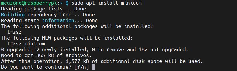
Install minicom:
sudo apt-get install minicom
Open AT Command serial port by minicom:
sudo minicom -D /dev/ttyUSB0

Then directly type the AT command and press Enter to see the result. If you need to view the echo, please type the command: ate1:
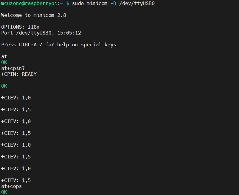
Note: The operation procedures are the same, but for different 4G models, the corresponding USB IDs will vary, so please refer to the actual USB ID using the lsusb command.
3.3.2 Common AT commands
1) Check if the SIM card is detected:
at+cpin?
Return ready to indicate the card has been recognized, if return error, you need to check the hardware.
2) Check antenna signal quality:
at+csq
Return values between 26 and 31 indicate a good signal, with 31 representing a full signal strength; return values between 20 and 25 indicate a barely acceptable signal; return values below 20 indicate a poor signal or that the antenna might not be connected.
3) Check network registration status:
at+cops?
Normally, it should return the network supporter's code: 7, where 7 represents 4G.
Note: The above command at+csq should not include a question mark, while the other two commands require a question mark.
4) View the SIM card's IMEI code:
at+cgsn
5) Reset 4G module (Sometimes, if you reinsert the SIM card, hot swapping may not work; in such cases, you can use this reset command to reset the module.):
at+reset
6) Disable radio frequency:
at+cfun=0
Enable radio frequency:
at+cfun=1
The two commands mentioned above can be used in pairs to allow the module to re-register with the network without restarting the 4G module.
3.4 Modify the IP address of the 4G
1) Qualcomm 4G/GPS,NL668-EU/EAU/AM, ZTE CAT4:
Set the 4G module's IP to directly obtain a public IP. Please execute the AT command:
Set the IP to public: AT+GTIPPASS=1
Set the IP to private: AT+GTIPPASS=0
Check whether the current IP is a public or private IP:AT+GTIPPASS?
2) CAT4 4G:
Execute the AT command:
AT+ROUTEIP=<newip>
Note: only addresses in the format of 192.168.x.1 are supported. If you set AT+ROUTEIP=192.168.3.1, the final IP address obtained will be 192.168.3.100. After making the changes, you need to power off and restart the system.
Query current IP: AT+ROUTEIP?, it returns two values, the first one is the old IP, and the second one is the new IP.
Test command: AT+ROUTEIP=?
3.5 GPS Testing
3.5.1 Qualcomm 4G-GPS and NL668-EU/EAU/AM
Execute the command lsusb, as shown in the figure below:
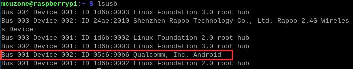
Note down the ID of the 4G module: 05c6 90b6.
Use the following command to open the ttyUSB serial port, where the value following echo is the ID value recorded above:
sudo modprobe option
sudo sh -c 'echo 05c6 90b6 > /sys/bus/usb-serial/drivers/option1/new_id'
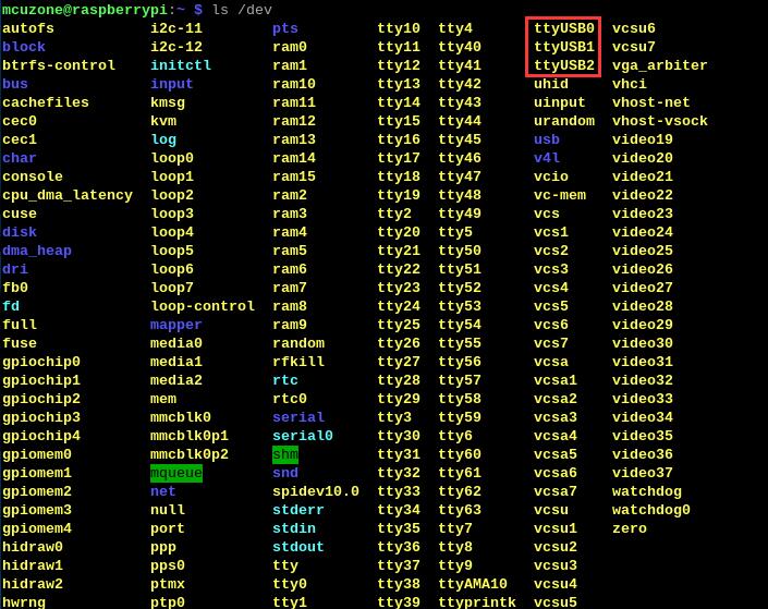
After executing the two commands above, the system should have three additional devices: ttyUSB0/1/2. You can check them by executing ls /dev:
Execute minicom and open the ttyUSB0 serial port:
sudo minicom -D /dev/ttyUSB0
Then execute:
at+gtgpsepo=1 //Enable AGPS
at+gtgpspower=1 //Enable GPS
Wait a moment for the positioning to succeed, then execute:
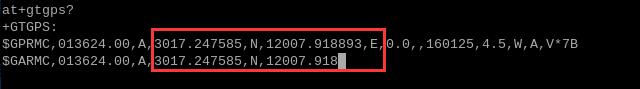
at+gtgps? //View NMEA information
You can then see that the serial port outputs GPS information:
3.5.2 EG25-GPS
Execute the command lsusb, as shown in the figure below:
Note down the ID of the 4G module: 2c7c 0125.
Use the following command to open the ttyUSB serial port, where the value following echo is the ID value recorded above:
sudo modprobe option
sudo sh -c 'echo 2c7c 0125 > /sys/bus/usb-serial/drivers/option1/new_id'
After executing the two commands above, the system should have three additional devices: ttyUSB0/1/2/3. You can check them by executing ls /dev/ttyUSB*:

Execute minicom and open the ttyUSB3 serial port:
sudo minicom -D /dev/ttyUSB3
Then execute:
AT+QGPS=1 //Open GPS
After executing successfully, open ttyUSB1:
sudo minicom -D /dev/ttyUSB1
You can then see that the serial port outputs GPS information; wait a moment for it to get a fix:
IV. Work with OpenWrt
We are using the Raspberry Pi Zero 2W with CAT4 4G to demonstrate running OpenWrt, can be configured as a one-in-one-out switch mode. The 4G module on the expansion board can serve as the WAN port (for direct 4G internet access), while the Ethernet port is configured as the LAN port for connecting to a PC.
The OpenWrt which be used in this document is: openwrt-bcm27xx-bcm2709-rpi-2-squashfs-sysupgrade-linux-6.1.98-20240723.img.gz
4.1 Configure the system
Connect the Ethernet port of the expansion board to the PC's Ethernet port using an Ethernet cable. The 4G module requires a mobile SIM card to be inserted. Power on and start the system. We find Network and Internet settings in Windows, then open the connected network under Ethernet to view the default gateway IP address. This address is the backend configuration page address for the OpenWrt system. As shown in the figure, the address for this test is 192.168.198.1:
Then open a web browser and enter 192.168.198.1 to access the OpenWrt system. The default username is root, and the default password is password:
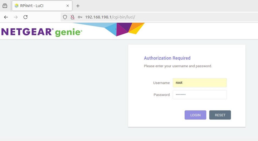
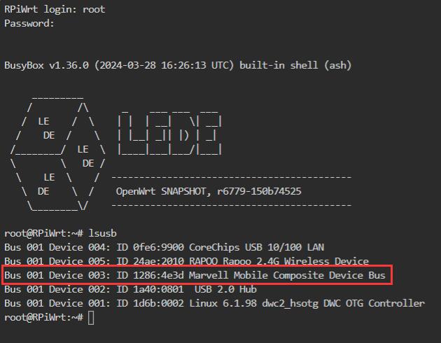
After logging into the OpenWrt system, click on "System - TTYD Terminal," then run lsusb to check if the 4G module is recognized. The red box in the image below indicates that the CAT4 4G module has been recognized.
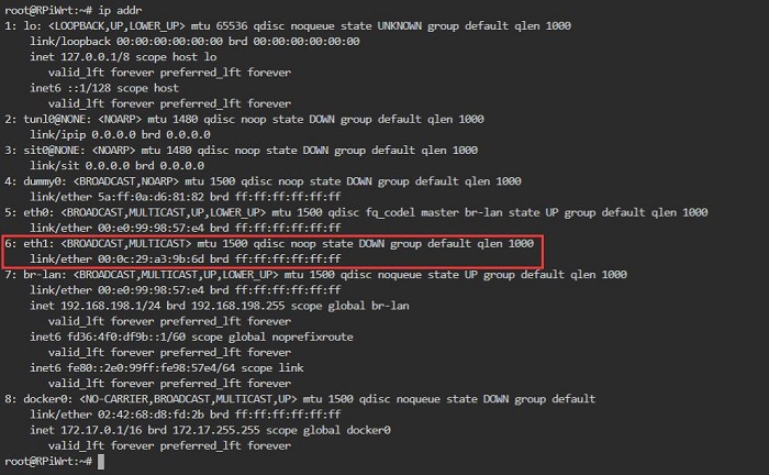
Execute the command ip addr to view all network devices. In the figure below, the No. 6, eth1 represents the network name of the CAT4 4G module. If you use NL668-AM/EU/EAU/Qualcomm 4G, this network name could be usb0. Please refer to the actual situation:
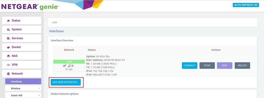
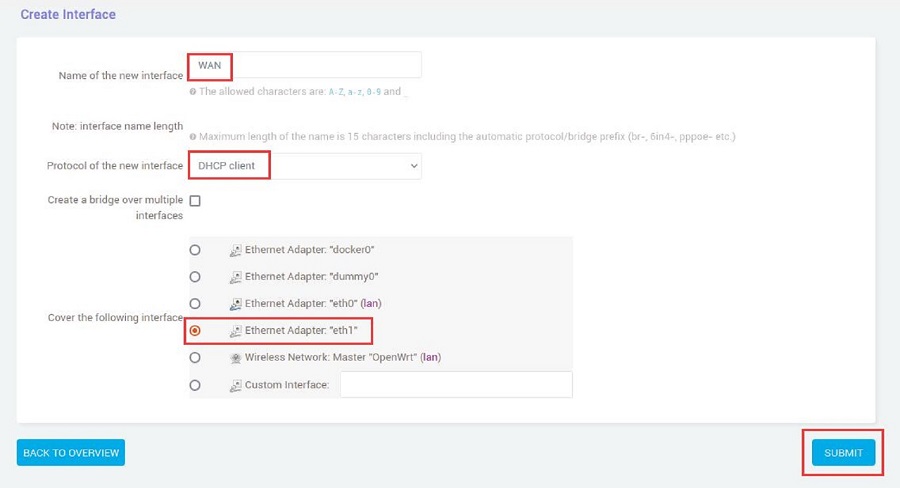
4.2 ADD the 4G module
Click on "Network - Interfaces," and then click on "ADD NEW INTERFACE...".
Set it up according to the following picture:
If 4G is NL668-AM/EU/EAU/Qualcomm 4G, Set it up as follows: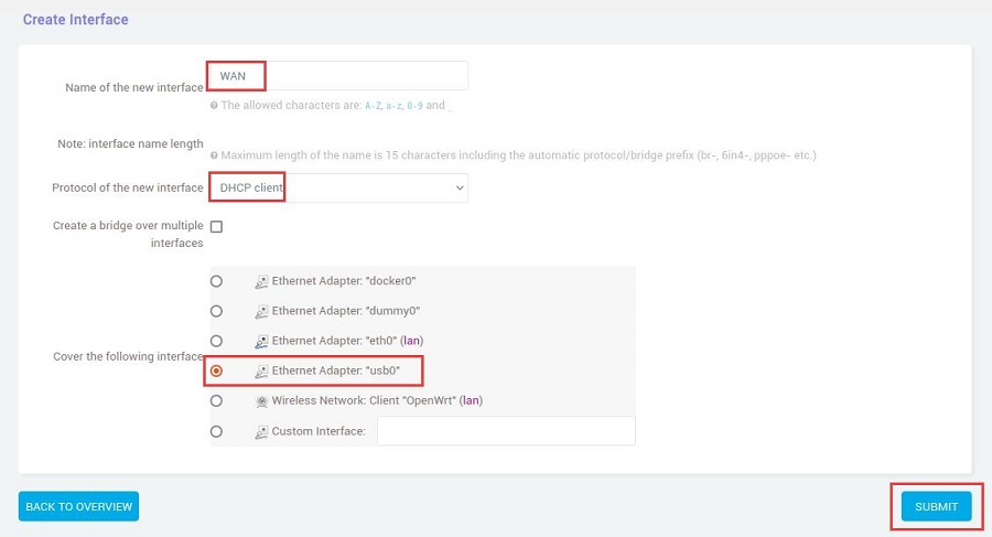
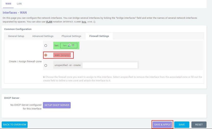
In the "Firewall Settings", select the WAN and then click the "SAVE & APPLY" button:
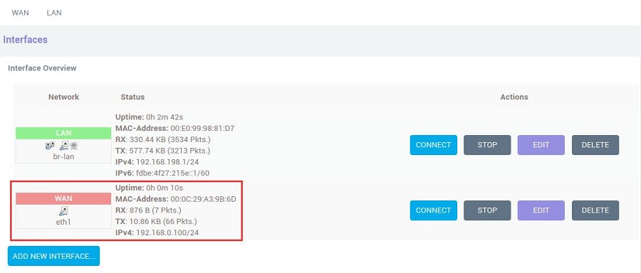
Go back to "Network - Interfaces", wait a moment, and you will see the newly created WAN interface has obtained an IP address. This way, the PC can access the internet through the 4G LTE module(in the two figures below, they are eth1 and usb0 respectively):
Open https://www.speedtest.cn/ on the PC to test speed. At this point, the PC can access the internet through the 4G LTE module, and the test results are as follows(CAT4 4G):
V. Expansion board selection guide
Contact Us


 QQ:8204136
Email: mcuzone@vip.qq.com
Tel: +86(0)13957118045
If there are any omissions, errors, or infringements on this page, please contact us through the above methods. Thank you!
Copyright 2004-2025 Wildchip