1004 RPi0 4G Cat1-GPS-ETH EN:修订间差异
| (未显示同一用户的11个中间版本) | |||
| 第1行: | 第1行: | ||
[[1004 | [[1004 RPi0 4G Cat1-GPS-ETH|切换语言为中文]] | ||
== '''Keywords''' == | == '''Keywords''' == | ||
| 第40行: | 第40行: | ||
http://www.mcuzone.com/wiki/1004_Zero_4G_Cat1-GPS/1004_Zero_4G_Cat1-GPS_08.jpg | http://www.mcuzone.com/wiki/1004_Zero_4G_Cat1-GPS/1004_Zero_4G_Cat1-GPS_08.jpg | ||
== '''III. | == '''III. Demonstration of using the Raspberry Pi OS''' == | ||
The hardware in this document is based on the Raspberry Pi Zero 2W. | |||
The Raspberry Pi OS used in this document is: 2024-07-04-raspios-bookworm-arm64.img.xz(Raspberry Pi OS with desktop). | |||
(If you are using the Raspberry Pi Zero (1st generation) series boards, they only support 32-bit systems. Please be sure to download the correct version.) | (If you are using the Raspberry Pi Zero (1st generation) series boards, they only support 32-bit systems. Please be sure to download the correct version.) | ||
| 第51行: | 第51行: | ||
https://www.raspberrypi.com/software/operating-systems/#raspberry-pi-os-64-bit | https://www.raspberrypi.com/software/operating-systems/#raspberry-pi-os-64-bit | ||
=== 3.1 View hardware devices === | |||
==== 3.1.1 View USB devices ==== | |||
== | |||
Open the terminal in Raspberry Pi OS and enter the command<code>lsusb</code>, as shown in the image below: | Open the terminal in Raspberry Pi OS and enter the command<code>lsusb</code>, as shown in the image below: | ||
| 第72行: | 第60行: | ||
The system has detected the USB hub and the 4G module: | The system has detected the USB hub and the 4G module: | ||
Device | Device 002: External USB Hub; | ||
Device | Device 003: 4G module; | ||
Device | Device 004: USB to 100Mbps Ethernet adapter; | ||
Device | Device 005: USB2.0-A Interface; | ||
Device | Device 006: USB2.0-A Interface. | ||
If the system stop at the Raspberry Pi logo and fails to boot: | If the system stop at the Raspberry Pi logo and fails to boot: | ||
| 第98行: | 第86行: | ||
http://www.mcuzone.com/wiki/0007_Zero_4G_Cat1/0007_Zero_4G_Cat1_57.jpg | http://www.mcuzone.com/wiki/0007_Zero_4G_Cat1/0007_Zero_4G_Cat1_57.jpg | ||
==== | ==== 3.1.2 View network devices ==== | ||
Open the terminal in Raspberry Pi OS and enter the command <code>ifconfig -a</code>, as shown in the image below: | Open the terminal in Raspberry Pi OS and enter the command <code>ifconfig -a</code>, as shown in the image below: | ||
| 第107行: | 第95行: | ||
'''''Note: The 4G Cat1 module of this expansion board initializes quickly and is connected to the first port of the USB Hub chip. SO, in the allocation of network names, the 4G Cat1 module is assigned as eth0, and the USB to Ethernet adapter is assigned as eth1.''''' | '''''Note: The 4G Cat1 module of this expansion board initializes quickly and is connected to the first port of the USB Hub chip. SO, in the allocation of network names, the 4G Cat1 module is assigned as eth0, and the USB to Ethernet adapter is assigned as eth1.''''' | ||
=== | === 3.2 Test network devices === | ||
==== | ==== 3.2.1 ping tests ==== | ||
When testing, there is a priority order: if eth0 is connected, it will be used first. If there are specific requirements for internal and external networks, please adjust the metric values of each network and the DNS server settings. | When testing, there is a priority order: if eth0 is connected, it will be used first. If there are specific requirements for internal and external networks, please adjust the metric values of each network and the DNS server settings. | ||
| 第132行: | 第120行: | ||
<code>sudo ifconfig eth0 up</code> | <code>sudo ifconfig eth0 up</code> | ||
==== | ==== 3.2.2 Set network card priority and designate DNS servers ==== | ||
For knowledge regarding this part, you can refer to the following link: | For knowledge regarding this part, you can refer to the following link: | ||
[[1001 | [[1001 RPi0 4G Cat1-ETH(100M ETH 4G Cat1 USB2.0-A RS485 version optional)#4.2.2 Set network adapter priority|1. Set network adapter priority]] | ||
[[1001 | [[1001 RPi0 4G Cat1-ETH(100M ETH 4G Cat1 USB2.0-A RS485 version optional)#4.2.3 Using udhcpc to specify DNS servers|2. Use udhcpc to specify DNS servers]] | ||
[[1001 | [[1001 RPi0 4G Cat1-ETH(100M ETH 4G Cat1 USB2.0-A RS485 version optional)#4.2.4 Examples of how to use udhcpc|3. udhcpc application scenario example]] | ||
It is recommended to specify the DNS server using the udhcpc software rather than editing the resolv.conf file, as this will be more stable. | It is recommended to specify the DNS server using the udhcpc software rather than editing the resolv.conf file, as this will be more stable. | ||
==== | ==== 3.2.3 Test speed by iperf3 ==== | ||
You can download iperf3 (Windows version) in: | You can download iperf3 (Windows version) in: | ||
http://www.mcuzone.com/down/Software.asp?ID=10000634 | |||
Install iperf3 (Linux version) by using the following command: | Install iperf3 (Linux version) by using the following command: | ||
| 第160行: | 第148行: | ||
4G CAT1 speed test results: | 4G CAT1 speed test results: | ||
http://www.mcuzone.com/wiki/0007_Zero_4G_Cat1/ | http://www.mcuzone.com/wiki/0007_Zero_4G_Cat1/0007_Zero_4G_Cat1_66.jpg | ||
'''''Note: Network speed testing is affected by the network environment and testing methods. Speeds should be considered based on actual results, and this test is for reference only.''''' | '''''Note: Network speed testing is affected by the network environment and testing methods. Speeds should be considered based on actual results, and this test is for reference only.''''' | ||
=== | === 3.3 Demonstration of AT Command === | ||
==== | ==== 3.3.1 Method to open AT Command serial port ==== | ||
To perform AT command operations on the 4G module in the Raspberry Pi, you first need to open the AT command serial port. The method to open it is as follows: | To perform AT command operations on the 4G module in the Raspberry Pi, you first need to open the AT command serial port. The method to open it is as follows: | ||
| 第209行: | 第197行: | ||
Note: The model of the 4G module may change, but the process remains the same. You only need to use <code>lsusb</code> to check the actual USB ID and replace it with the actual value in subsequent commands. Additionally, some 4G Cat1 modules' chipset IDs have already been included in the kernel's supported list, so these Cat1 modules can be automatically recognized as ttyAMAx without the need to add a USB ID. | Note: The model of the 4G module may change, but the process remains the same. You only need to use <code>lsusb</code> to check the actual USB ID and replace it with the actual value in subsequent commands. Additionally, some 4G Cat1 modules' chipset IDs have already been included in the kernel's supported list, so these Cat1 modules can be automatically recognized as ttyAMAx without the need to add a USB ID. | ||
==== | ==== 3.3.2 Common AT commands ==== | ||
1) Check if the SIM card is detected: | 1) Check if the SIM card is detected: | ||
| 第250行: | 第238行: | ||
http://www.mcuzone.com/wiki/0007_Zero_4G_Cat1/0007_Zero_4G_Cat1_15.jpg | http://www.mcuzone.com/wiki/0007_Zero_4G_Cat1/0007_Zero_4G_Cat1_15.jpg | ||
==== | ==== 3.3.3 Test GPS ==== | ||
When using GPS, a '''passive GPS antenna''' is used by default, and ensure that the GPS antenna is extended outdoors. | When using GPS, a '''passive GPS antenna''' is used by default, and ensure that the GPS antenna is extended outdoors. | ||
| 第271行: | 第259行: | ||
After running successfully, GPS information will be output on the serial port, and after a short wait, positioning will be achieved. | After running successfully, GPS information will be output on the serial port, and after a short wait, positioning will be achieved. | ||
http://www.mcuzone.com/wiki/1004_Zero_4G_Cat1-GPS/1004_Zero_4G_Cat1- | http://www.mcuzone.com/wiki/1004_Zero_4G_Cat1-GPS/1004_Zero_4G_Cat1-GPS_10a.jpg | ||
== '''IV. Demonstration of using the Ubuntu Server''' == | |||
The hardware in this document is based on the Raspberry Pi Zero 2W. | |||
Ubuntu system: Ubuntu Server 24.04 LTS. (The Raspberry Pi Zero 2W cannot use the Desktop version due to performance limitations.) | |||
The image is: ubuntu-24.04-preinstalled-server-arm64+raspi.img.xz | |||
You can download the Ubuntu system in: | |||
https://ubuntu.com/download/raspberry-pi | |||
=== | === 4.1 Edit the initialization script === | ||
After flashing Ubuntu Server, please open the config.txt file in the root directory of the TF card on | After flashing Ubuntu Server, please open the <code>config.txt</code> file located in the root directory of the system partition on the TF card on your PC to check the initialization script for USB. Ubuntu Server initializes the USB twice, but the first initialization does not configure it in host mode. Please verify that the area highlighted in red in the following image is configured properly. If it is not, please manually add the complete configuration: | ||
<code>dtoverlay=dwc2,dr_mode=host</code> | <code>dtoverlay=dwc2,dr_mode=host</code> | ||
| 第282行: | 第279行: | ||
http://www.mcuzone.com/wiki/0007_Zero_4G_Cat1/0007_Zero_4G_Cat1_32.jpg | http://www.mcuzone.com/wiki/0007_Zero_4G_Cat1/0007_Zero_4G_Cat1_32.jpg | ||
http://www.mcuzone.com/wiki/0007_Zero_4G_Cat1/ | http://www.mcuzone.com/wiki/0007_Zero_4G_Cat1/0007_Zero_4G_Cat1_75.jpg | ||
=== | === 4.2 Configure username and password === | ||
Insert the TF card into the Zero 2W and boot the system. Upon the first boot, you will be prompted to log in. The username and password are both ubuntu. After successful login, you will be prompted to change the password: | Insert the TF card into the Zero 2W and boot the system. Upon the first boot, you will be prompted to log in. The username and password are both ubuntu. After successful login, you will be prompted to change the password: | ||
| 第291行: | 第288行: | ||
修改完毕后就自动进入系统。 | 修改完毕后就自动进入系统。 | ||
=== | === 4.3 Configure network === | ||
For security reasons, the Ubuntu Server system has many restrictions by default, and numerous servers and components are also in a disabled state; this includes network interfaces being turned off. So, after the system starts, there is no network available, and it needs to be configured to be usable. | For security reasons, the Ubuntu Server system has many restrictions by default, and numerous servers and components are also in a disabled state; this includes network interfaces being turned off. So, after the system starts, there is no network available, and it needs to be configured to be usable. | ||
| 第316行: | 第313行: | ||
http://www.mcuzone.com/wiki/0007_Zero_4G_Cat1/0007_Zero_4G_Cat1_35.jpg | http://www.mcuzone.com/wiki/0007_Zero_4G_Cat1/0007_Zero_4G_Cat1_35.jpg | ||
=== | === 4.4 Network and 4G Module Test === | ||
Execute the command <code>ifconfig -a</code> to view the network interface information: | Execute the command <code>ifconfig -a</code> to view the network interface information: | ||
| 第327行: | 第324行: | ||
http://www.mcuzone.com/wiki/0007_Zero_4G_Cat1/0007_Zero_4G_Cat1_37.jpg | http://www.mcuzone.com/wiki/0007_Zero_4G_Cat1/0007_Zero_4G_Cat1_37.jpg | ||
=== | === 4.5 Demonstration of AT Command === | ||
Install minicom: | Install minicom: | ||
| 第348行: | 第345行: | ||
http://www.mcuzone.com/wiki/0007_Zero_4G_Cat1/0007_Zero_4G_Cat1_40.jpg | http://www.mcuzone.com/wiki/0007_Zero_4G_Cat1/0007_Zero_4G_Cat1_40.jpg | ||
=== | === 4.6 Test GPS === | ||
When using GPS, a '''passive GPS antenna''' is used by default, and ensure that the GPS antenna is extended outdoors. | When using GPS, a '''passive GPS antenna''' is used by default, and ensure that the GPS antenna is extended outdoors. | ||
| 第369行: | 第366行: | ||
After running successfully, GPS information will be output on the serial port, and after a short wait, positioning will be achieved. | After running successfully, GPS information will be output on the serial port, and after a short wait, positioning will be achieved. | ||
http://www.mcuzone.com/wiki/1004_Zero_4G_Cat1-GPS/1004_Zero_4G_Cat1- | http://www.mcuzone.com/wiki/1004_Zero_4G_Cat1-GPS/1004_Zero_4G_Cat1-GPS_09a.jpg | ||
== ''' | == '''V. Demonstration of Using the OpenWrt''' == | ||
=== | === 5.1 Overview === | ||
This expansion board, when paired with the Raspberry Pi Zero 2W running OpenWrt, can be configured as a one-in-one-out switch mode. The 4G module on the expansion board can serve as the WAN port (for direct 4G internet access), while the Ethernet port is configured as the LAN port for connecting to a PC. | This expansion board, when paired with the Raspberry Pi Zero 2W running OpenWrt, can be configured as a one-in-one-out switch mode. The 4G module on the expansion board can serve as the WAN port (for direct 4G internet access), while the Ethernet port is configured as the LAN port for connecting to a PC. | ||
=== | === 5.2 Preparation === | ||
The OpenWrt which be used in this document is: openwrt-bcm27xx-bcm2709-rpi-2-squashfs-sysupgrade-linux-6.1.98-20240723.img.gz | The OpenWrt which be used in this document is: openwrt-bcm27xx-bcm2709-rpi-2-squashfs-sysupgrade-linux-6.1.98-20240723.img.gz | ||
| 第385行: | 第382行: | ||
Then open a web browser and enter 192.168.198.1 to access the OpenWrt system. The default username is <code>root</code>, and the default password is <code>password</code>.http://www.mcuzone.com/wiki/0007_Zero_4G_Cat1/0007_Zero_4G_Cat1_19.jpg | Then open a web browser and enter 192.168.198.1 to access the OpenWrt system. The default username is <code>root</code>, and the default password is <code>password</code>.http://www.mcuzone.com/wiki/0007_Zero_4G_Cat1/0007_Zero_4G_Cat1_19.jpg | ||
=== | === 5.3 Configure the OpenWrt system === | ||
After entering the OpenWrt system, connect the Raspberry Pi's Ethernet port directly to the PC's Ethernet port using an Ethernet cable. Once the PC's network card has acquired an IP address, the PC can directly access the internet through the 4G module (no additional settings required). | After entering the OpenWrt system, connect the Raspberry Pi's Ethernet port directly to the PC's Ethernet port using an Ethernet cable. Once the PC's network card has acquired an IP address, the PC can directly access the internet through the 4G module (no additional settings required). | ||
=== | === 5.4 Test the network speed of 4G module === | ||
On the PC, open <nowiki>https://www.speedtest.cn/</nowiki> to perform a speed test. At this point, the traffic goes through the 4G module, and the test results are as follows: | On the PC, open <nowiki>https://www.speedtest.cn/</nowiki> to perform a speed test. At this point, the traffic goes through the 4G module, and the test results are as follows: | ||
http://www.mcuzone.com/wiki/0007_Zero_4G_Cat1/ | http://www.mcuzone.com/wiki/0007_Zero_4G_Cat1/0007_Zero_4G_Cat1_66.jpg | ||
'''''Note: The speed of 4G network testing is influenced by network signal strength and the testing method, so actual speeds may vary.''''' | '''''Note: The speed of 4G network testing is influenced by network signal strength and the testing method, so actual speeds may vary.''''' | ||
=== | === 5.5 Mounting USB drive and file operations === | ||
When you insert a USB drive into a USB port, you can directly see the information and mounting status of the USB drive in "System - Disk Management": | When you insert a USB drive into a USB port, you can directly see the information and mounting status of the USB drive in "System - Disk Management": | ||
| 第404行: | 第401行: | ||
In the "Network Storage - File Assistant" section, you can perform operations on files within the system.http://www.mcuzone.com/wiki/0007_Zero_4G_Cat1/0007_Zero_4G_Cat1_21.jpg | In the "Network Storage - File Assistant" section, you can perform operations on files within the system.http://www.mcuzone.com/wiki/0007_Zero_4G_Cat1/0007_Zero_4G_Cat1_21.jpg | ||
=== | === 5.6 TTYD terminal === | ||
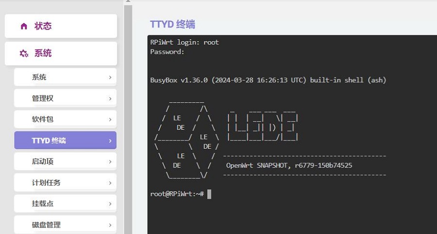
The OpenWrt system comes with a web-based TTYD terminal, which can be accessed in the "System - TTYD Terminal" section. The default username is <code>root</code>, and the default password is <code>password</code>. Since you log in with the root account, you will have root privileges upon logging in: | The OpenWrt system comes with a web-based TTYD terminal, which can be accessed in the "System - TTYD Terminal" section. The default username is <code>root</code>, and the default password is <code>password</code>. Since you log in with the root account, you will have root privileges upon logging in: | ||
2024年11月15日 (五) 10:17的最新版本
Keywords
Raspberry, Raspberry Pi Zero, Cat1 4G LTE, USB2.0-A, Ethernet, Expansion Board, USB HUB, GPS, GNSS
I. Introduction
The Raspberry Pi Zero series (including the Zero, Zero W/H, and Zero 2W) is a highly cost-effective embedded system platform, known for its small size, low power consumption, and acceptable performance, making it suitable for many lightweight application scenarios. Although the Zero series is compact, it reserves a large number of expansion interfaces. Especially on the backside of the board, gold-plated test points for USB and power are brought out. We can use these sets of USB and power test points to expand various types of peripherals. This expansion board is essentially a USB hub that connects to the Zero's USB port via pogo pins. It expands four USB ports via USB, with one USB port converted to a 100Mbps wired Ethernet port, one USB port connected to a 4G Cat1 module, and two USB 2.0-A host ports.
4G Cat1 is a high-cost-performance module aimed at medium-speed IoT applications around 10 Mbps. The 10 Mbps downlink and 5 Mbps uplink speeds can satisfy the majority of connectivity and transmission requirements. It supports 4G all-net communications, including Unicom, Telecom, and Mobile. The 4G module on this expansion board also supports GPS/GNSS..
II. Hardware Resources
2.1 Use gold-plated pogo pins to connect the Raspberry Pi Zero series, eliminating the need for external cables;
2.2 The two groups of gold-plated pogo pins are used separately for power supply and USB communication.
2.3The expansion board is equipped with a USB-C power supply interface, which can power the entire system. The Micro USB port on the Zero can also be used for power.
2.4 The onboard USB hub expands the Zero's USB into four ports: one port is used for connecting a 4G LTE Cat1 module, two are USB host interfaces, and one is a USB to 10/100Mbps Ethernet adapter.
2.5 4G LTE Cat1 module supports full 4G network coverage, with a downlink speed of up to 10Mbps and an uplink speed of up to 5Mbps.
2.6 The 4G LTE Cat1 module is a plug-and-play in most systems, driver-free and does not require manual dialing, usually recognized as the eth1 network card.
2.7 The 4G LTE Cat1 module uses a Nano-sized SIM card and offers the option of either an SMA antenna or a first-generation IPEX antenna.
2.8 The 4G LTE Cat1 module supports GPS/GNSS.
2.9 The expansion board supportsother Pi with USB contacts in the same position, such as the Orange Pi Zero 2W.
2.10 Onboard PWR/MODE/ACT LED.
2.11 Onboard reset button for 4G module.
Note 1: After connecting this expansion board, the Micro USB port on the Zero will no longer be usable.
Note 2: In some systems, it is necessary to disable the OTG function and set the USB mode to Host mode.
Note 3: The expansion board supports all versions of the Raspberry Pi Zero, including the Zero, Zero W, Zero WH, and Zero 2W.

III. Demonstration of using the Raspberry Pi OS
The hardware in this document is based on the Raspberry Pi Zero 2W.
The Raspberry Pi OS used in this document is: 2024-07-04-raspios-bookworm-arm64.img.xz(Raspberry Pi OS with desktop).
(If you are using the Raspberry Pi Zero (1st generation) series boards, they only support 32-bit systems. Please be sure to download the correct version.)
You can download the Raspberry Pi OS in:
https://www.raspberrypi.com/software/operating-systems/#raspberry-pi-os-64-bit
3.1 View hardware devices
3.1.1 View USB devices
Open the terminal in Raspberry Pi OS and enter the commandlsusb, as shown in the image below:

The system has detected the USB hub and the 4G module:
Device 002: External USB Hub;
Device 003: 4G module;
Device 004: USB to 100Mbps Ethernet adapter;
Device 005: USB2.0-A Interface;
Device 006: USB2.0-A Interface.
If the system stop at the Raspberry Pi logo and fails to boot:
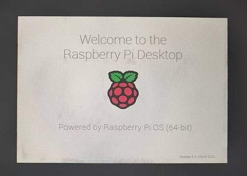
or if after booting, the keyboard, mouse, and 4G module cannot be used, please carefully check whether the pogo pins are aligned with the gold-plated contacts. Additionally, on the PC, open the config.txt file located in the root directory of the TF card to check the USB initialization script.
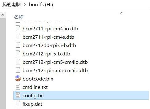
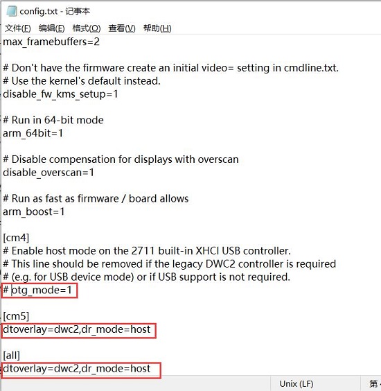
You need to confirm that the three red-boxed areas in the following image are all configured completely. If not, please manually add the missing parts and save the file:
# otg_mode=1 (It is recommended to comment out as follow)
dtoverlay=dwc2,dr_mode=host (These two areas must be ensured to be included.)
3.1.2 View network devices
Open the terminal in Raspberry Pi OS and enter the command ifconfig -a, as shown in the image below:
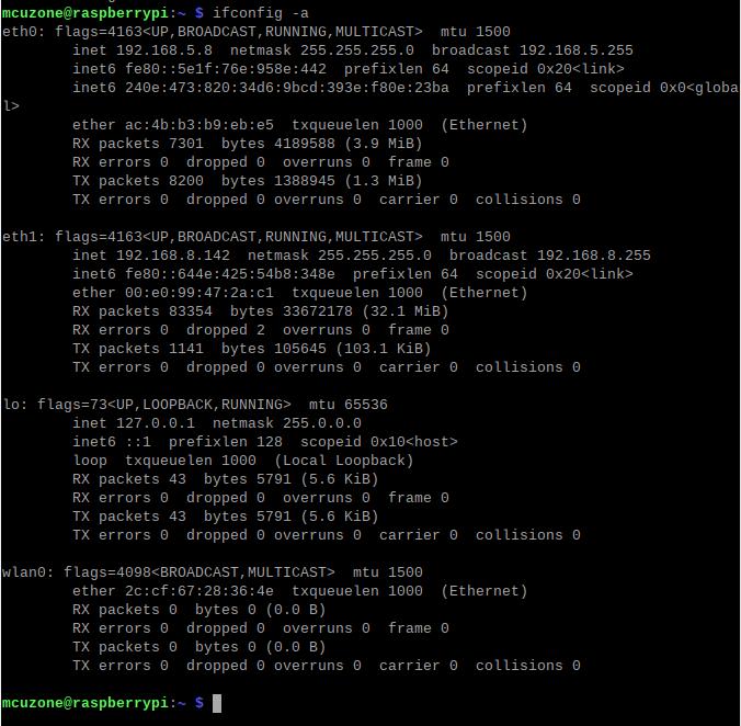
You can see that eth0 is 4G Cat1 (with the default IP address of 192.168.5.8 in the image above), and eth1 is the USB to Ethernet conversion.
Note: The 4G Cat1 module of this expansion board initializes quickly and is connected to the first port of the USB Hub chip. SO, in the allocation of network names, the 4G Cat1 module is assigned as eth0, and the USB to Ethernet adapter is assigned as eth1.
3.2 Test network devices
3.2.1 ping tests
When testing, there is a priority order: if eth0 is connected, it will be used first. If there are specific requirements for internal and external networks, please adjust the metric values of each network and the DNS server settings.
Use the -I parameter to specify which network interface to start the ping packet from, as shown below:
ping www.mcuzone.com -I eth0
ping www.mcuzone.com -I eth1
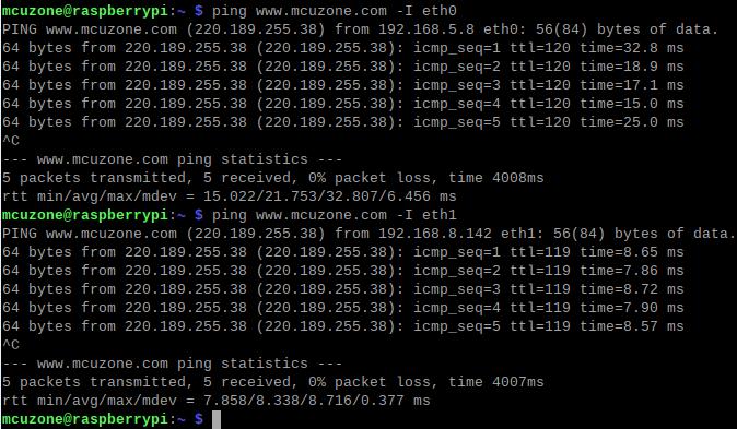
Priority can be checked by executing the route command; the network card with the smaller metric value will be preferred for communication

We can also force communication through another network by disabling a specific network card. For example, to disable eth0, you can execute the following command:
sudo ifconfig eth0 down
And enable eth0 by the following command:
sudo ifconfig eth0 up
3.2.2 Set network card priority and designate DNS servers
For knowledge regarding this part, you can refer to the following link:
1. Set network adapter priority
2. Use udhcpc to specify DNS servers
3. udhcpc application scenario example
It is recommended to specify the DNS server using the udhcpc software rather than editing the resolv.conf file, as this will be more stable.
3.2.3 Test speed by iperf3
You can download iperf3 (Windows version) in:
http://www.mcuzone.com/down/Software.asp?ID=10000634
Install iperf3 (Linux version) by using the following command:
sudo apt-get install iperf3
100M Ethernet speed test results: It is about 75Mbps in client mode and it is about 94Mbps in server mode:
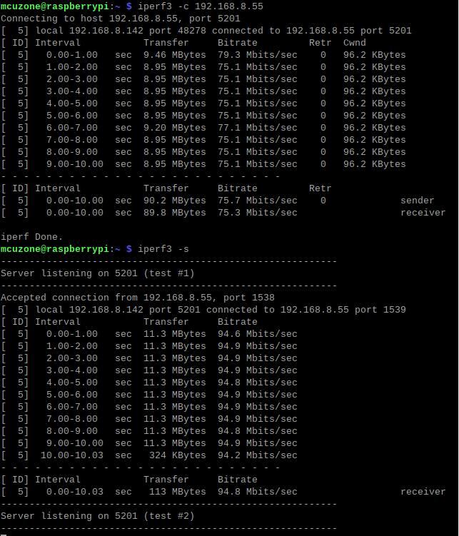
Note: The USB to 100M Ethernet adapter may not reach full speed due to the performance limitations of the Zero 2W, the USB hub, and the bandwidth usage of the 4G Cat1.
4G CAT1 speed test results:
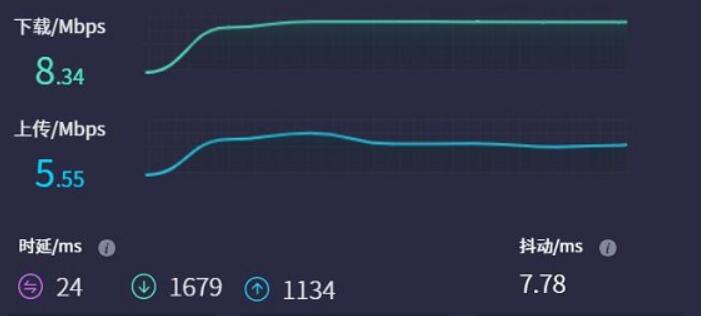
Note: Network speed testing is affected by the network environment and testing methods. Speeds should be considered based on actual results, and this test is for reference only.
3.3 Demonstration of AT Command
3.3.1 Method to open AT Command serial port
To perform AT command operations on the 4G module in the Raspberry Pi, you first need to open the AT command serial port. The method to open it is as follows:
Open the ttyUSB serial port:
Input the following command: lsusb

Record the ID value of the 4G module: 1782 4e00
Use the following command to open the ttyUSB serial port, where the value after echo is the ID recorded above:
sudo modprobe option
sudo sh -c 'echo 1782 4e00 > /sys/bus/usb-serial/drivers/option1/new_id'

After execution is complete, the system should have three additional devices: ttyUSB0, ttyUSB1, and ttyUSB2.
Then use a serial port tool to open the corresponding serial port.
Install minicom:
sudo apt-get install minicom

Open AT Command serial port by minicom:
sudo minicom -D /dev/ttyUSB0
Or:
sudo minicom -D /dev/ttyUSB1

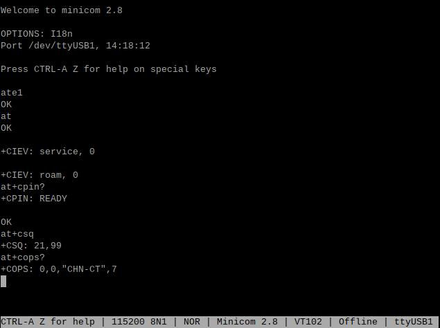
Then directly type the AT command and press Enter to see the result. If you need to view the echo, please type the command: ate1.
Note: The model of the 4G module may change, but the process remains the same. You only need to use lsusb to check the actual USB ID and replace it with the actual value in subsequent commands. Additionally, some 4G Cat1 modules' chipset IDs have already been included in the kernel's supported list, so these Cat1 modules can be automatically recognized as ttyAMAx without the need to add a USB ID.
3.3.2 Common AT commands
1) Check if the SIM card is detected:
at+cpin?
Return ready to indicate the card has been recognized, if return error, you need to check the hardware.
2) Check antenna signal quality:
at+csq
eturn values between 26 and 31 indicate a good signal, with 31 representing a full signal strength; return values between 20 and 25 indicate a barely acceptable signal; return values below 20 indicate a poor signal or that the antenna might not be connected.
3) Check network registration status:
at+cops?
Normally, it should return the network supporter's code: 7, where 7 represents 4G.
Note: The above command at+csq should not include a question mark, while the other two commands require a question mark.
4) View the SIM card's IMEI code:
at+cgsn
5) Reset 4G module (Sometimes, if you reinsert the SIM card, hot swapping may not work; in such cases, you can use this reset command to reset the module.):
at+reset
6) Disable radio frequency:
at+cfun=0
Enable radio frequency:
at+cfun=1
The two commands mentioned above can be used in pairs to allow the module to re-register with the network without restarting the 4G module.
3.3.3 Test GPS
When using GPS, a passive GPS antenna is used by default, and ensure that the GPS antenna is extended outdoors.
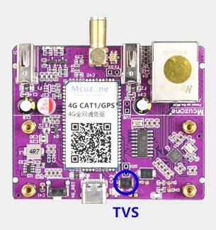
Note: Some passive GPS antennas are sensitive to the parasitic capacitance of the TVS diodes used for protection. If satellite acquisition fails, you may need to remove the TVS diodes and try again (as shown in the figure). If you want to use an active antenna, you need to replace capacitor C43 with a 0Ω resistor.
Run minicom to open the ttyUSB1 serial port:
sudo minicom -D /dev/ttyUSB1
And run:
AT+CGNSPWR=1 //Open GPS
AT+CGNSAID=31,1,1,1 //Enable position assistance (the command returns OK immediately, and positioning should succeed within approximately 2-10 seconds based on signal strength).
AT+CGNSURC=1 //Set up automatic reporting of location information
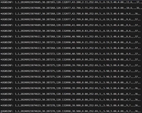
After running successfully, GPS information will be output on the serial port, and after a short wait, positioning will be achieved.
IV. Demonstration of using the Ubuntu Server
The hardware in this document is based on the Raspberry Pi Zero 2W.
Ubuntu system: Ubuntu Server 24.04 LTS. (The Raspberry Pi Zero 2W cannot use the Desktop version due to performance limitations.)
The image is: ubuntu-24.04-preinstalled-server-arm64+raspi.img.xz
You can download the Ubuntu system in:
https://ubuntu.com/download/raspberry-pi
4.1 Edit the initialization script
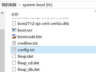
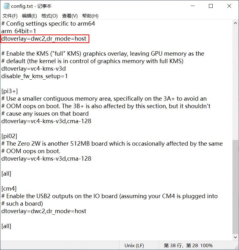
After flashing Ubuntu Server, please open the config.txt file located in the root directory of the system partition on the TF card on your PC to check the initialization script for USB. Ubuntu Server initializes the USB twice, but the first initialization does not configure it in host mode. Please verify that the area highlighted in red in the following image is configured properly. If it is not, please manually add the complete configuration:
dtoverlay=dwc2,dr_mode=host
4.2 Configure username and password
Insert the TF card into the Zero 2W and boot the system. Upon the first boot, you will be prompted to log in. The username and password are both ubuntu. After successful login, you will be prompted to change the password:

修改完毕后就自动进入系统。
4.3 Configure network
For security reasons, the Ubuntu Server system has many restrictions by default, and numerous servers and components are also in a disabled state; this includes network interfaces being turned off. So, after the system starts, there is no network available, and it needs to be configured to be usable.
Note: The system does not include the ifconfig tool by default; only the ip command is available.
Execute ip addr to view and record the name of the NIC.

Among these, network card number 2 (enx00e0996df1cd) is the USB-to-100Mbps Ethernet adapter, and network card number 3 (enxac4bb3b9ebe5) is the 4G module.
Then run the following command to open the network interface configuration file:
sudo nano /etc/netplan/50-cloud-init.yaml
Edit the network interface configuration file according to the following diagram:
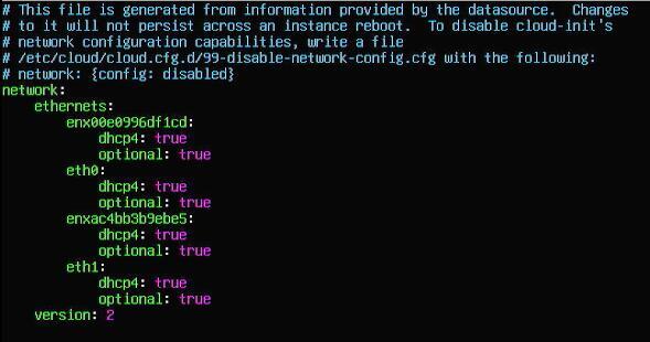
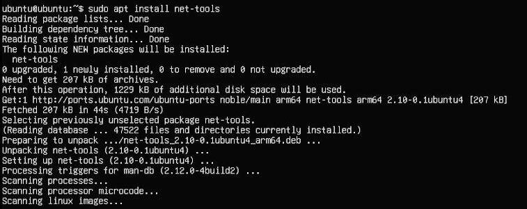
Save and exit, then restart the system. After restarting, you can connect to the network and install the net-tools package for easy use:
sudo apt install net-tools
4.4 Network and 4G Module Test
Execute the command ifconfig -a to view the network interface information:
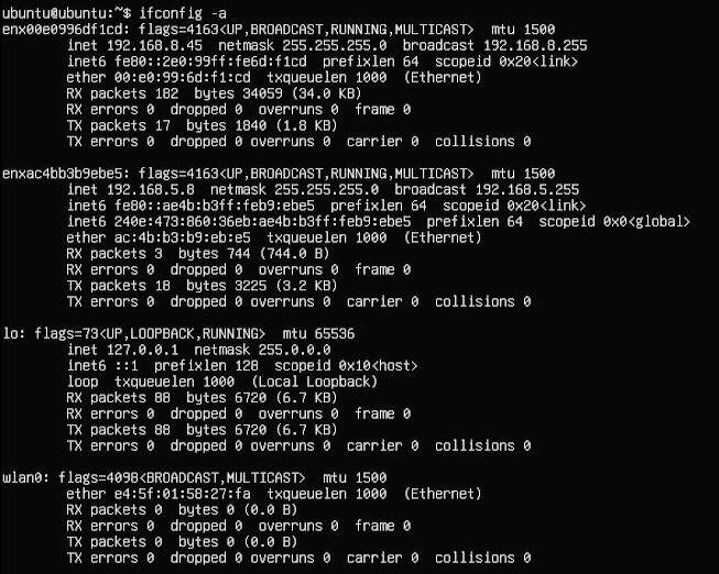
The first network interface is the USB-to-100Mbps Ethernet adapter, and the second network interface is the 4G module.
By using the -I parameter and adding the network interface name when sending ping packets, you can specify which network interface should send the ping packets:
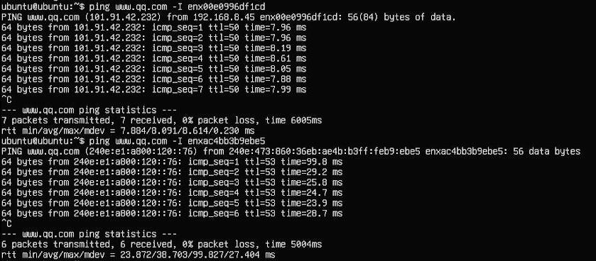
4.5 Demonstration of AT Command
Install minicom:
sudo apt-get install minicom
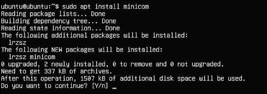
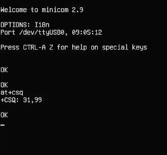
Open AT Command serial port by minicom:
sudo minicom -D /dev/ttyUSB0
Or:
sudo minicom -D /dev/ttyUSB1

Then you can use AT Commands.
4.6 Test GPS
When using GPS, a passive GPS antenna is used by default, and ensure that the GPS antenna is extended outdoors.
Note: Some passive GPS antennas are sensitive to the parasitic capacitance of the TVS diodes used for protection. If satellite acquisition fails, you may need to remove the TVS diodes and try again (as shown in the figure). If you want to use an active antenna, you need to replace capacitor C43 with a 0Ω resistor.

Run minicom to open the ttyUSB1 serial port:
sudo minicom -D /dev/ttyUSB1
And run:
AT+CGNSPWR=1 //Open GPS
AT+CGNSAID=31,1,1,1 //Enable position assistance (the command returns OK immediately, and positioning should succeed within approximately 2-10 seconds based on signal strength).
AT+CGNSURC=1 //Set up automatic reporting of location information
After running successfully, GPS information will be output on the serial port, and after a short wait, positioning will be achieved.

V. Demonstration of Using the OpenWrt
5.1 Overview
This expansion board, when paired with the Raspberry Pi Zero 2W running OpenWrt, can be configured as a one-in-one-out switch mode. The 4G module on the expansion board can serve as the WAN port (for direct 4G internet access), while the Ethernet port is configured as the LAN port for connecting to a PC.
5.2 Preparation
The OpenWrt which be used in this document is: openwrt-bcm27xx-bcm2709-rpi-2-squashfs-sysupgrade-linux-6.1.98-20240723.img.gz
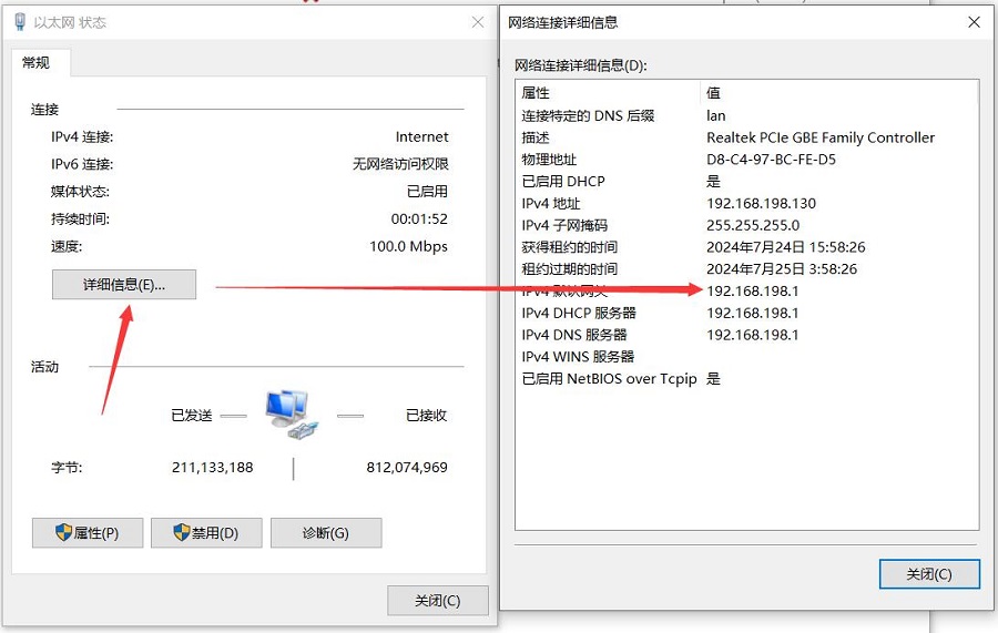
After flashing the OpenWrt system and powering it up, we connect an Ethernet cable from the Raspberry Pi's built-in Ethernet port to the PC's Ethernet port. Once the connection between the PC's network card and the Raspberry Pi's Ethernet port is successful, we find Network and Internet settings in Windows, then open the connected network under Ethernet to view the default gateway IP address. This address is the backend configuration page address for the OpenWrt system. As shown in the figure, the address for this test is 192.168.198.1:
Then open a web browser and enter 192.168.198.1 to access the OpenWrt system. The default username is root, and the default password is password.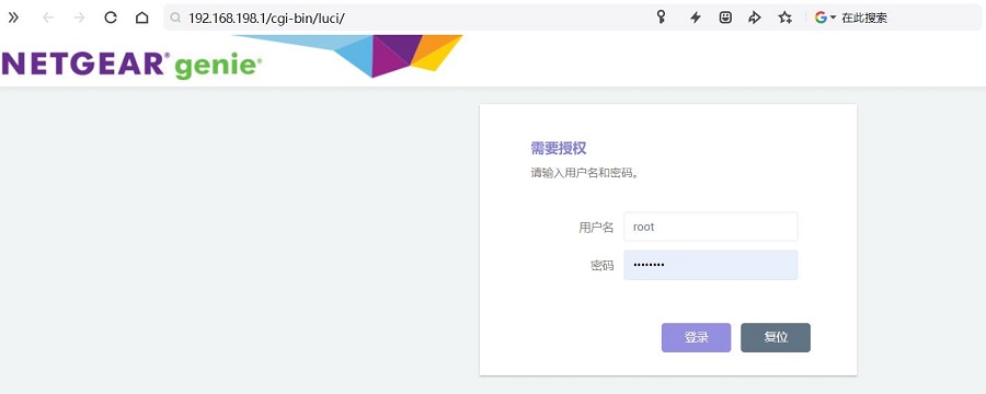
5.3 Configure the OpenWrt system
After entering the OpenWrt system, connect the Raspberry Pi's Ethernet port directly to the PC's Ethernet port using an Ethernet cable. Once the PC's network card has acquired an IP address, the PC can directly access the internet through the 4G module (no additional settings required).
5.4 Test the network speed of 4G module
On the PC, open https://www.speedtest.cn/ to perform a speed test. At this point, the traffic goes through the 4G module, and the test results are as follows:

Note: The speed of 4G network testing is influenced by network signal strength and the testing method, so actual speeds may vary.
5.5 Mounting USB drive and file operations
When you insert a USB drive into a USB port, you can directly see the information and mounting status of the USB drive in "System - Disk Management":

In the "System - Mount Points" section, you can see the status of all mount points and can configure them on this page.
In the "Network Storage - File Assistant" section, you can perform operations on files within the system.
5.6 TTYD terminal
The OpenWrt system comes with a web-based TTYD terminal, which can be accessed in the "System - TTYD Terminal" section. The default username is root, and the default password is password. Since you log in with the root account, you will have root privileges upon logging in:
Contact Us
Email: mcuzone@vip.qq.com
Tel: +86(0)13957118045
If there are any omissions, errors, or infringements on this page, please contact us through the above methods. Thank you!
Copyright 2004-2024 Wildchip


 QQ:8204136